Table of Contents
Advertisement
Quick Links
Advertisement
Table of Contents

Related Manuals for Insportline IN 2678 Excel Run


Summary of Contents for Insportline IN 2678 Excel Run
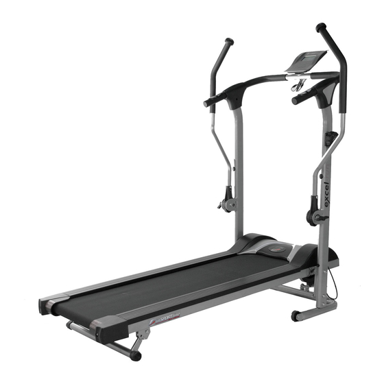
- Page 1 USER MANUAL – EN IN 2678 Magnetic Treadmill inSPORTline Excel...
-
Page 2: Table Of Contents
CONTENTS SAFETY INSTRUCTIONS ........................3 EXPLODED DIAGRAM ........................... 4 PARTS LIST ............................5 ASSEMBLY MATERIAL .......................... 7 OVERVIEW OF PARTS .......................... 8 ASSEMBLY ............................. 9 Step 1 ..............................9 Step 2 ..............................10 Step 3 ..............................11 Step 4 ..............................12 Step 5 .............................. -
Page 3: Safety Instructions
SAFETY INSTRUCTIONS • Move naturally during exercise. Do not look at your feet. Only one person can use the product at the same time. • Assembly the product according to the manual. For adults only. • Keep away from kids and pets. Do not leave kids and pets near the device unattended. Only for adult use. -
Page 4: Exploded Diagram
EXPLODED DIAGRAM... -
Page 5: Parts List
PARTS LIST NAME AND SPECIFICATION Bolt M8X15 Washer Arc Washer Plastic Washer Washer ID6.2 Bolt M8X50 Big Washer Bolt M8X45 Bolt M8*70 Bolt M8*40 Nut M8 Sleeve Screw M4*15 Knob M8 Pin φ8 Wrench S13 Allen key S5 Main Frame Rear Roller Plastic Washer End cap - steel... - Page 6 Magnetic braking system Nut M8 Bolt M8*40 Plastic Wheel Base Frame Cushion Bottom Frame Right Side Handle Post Tension Bolt M5*20 27R– R, L Handle cover 28L – R, L Handle cover Handle Bar Bolt M8*35 Sensor Wire Connector Screw M5*25L Left Side Handle Post Washer Spring...
-
Page 7: Assembly Material
ASSEMBLY MATERIAL SPECIFICATION M8*70 M8*50 M8*45 M8*40 M8*15 M4*15 OD16.8*ID8.2 OD16.8*ID8.2 OD22*ID8.2 OD13*ID6.2 OD59*ID38 OD12.7*ID8.2*11L ø8 13 mm... -
Page 8: Overview Of Parts
OVERVIEW OF PARTS NAME NAME Main Frame Handle Bar Left Side Computer Handle Post Extension 14L&14R Handle bar tube Bottom Frame Plastic Cover Right Side Cover of 27R-R&L Handle Post handle... -
Page 9: Assembly
ASSEMBLY • Read this manual before assembly. • Check the hardware. • Ensure that you have the right tools. • Prepare an area to assemble. • Follow the instruction accordingly. • Do not use force for assembly. • Periodically tighten the treadmill. •... -
Page 10: Step 2
Step 2 Fasteners M8x50 OD22xID8,2 Ø8 5 mm Connect left handle post (33) and right handle post (24) to main frame (1). Secure with bolt (F) and big washer (G). Connect pin (O). -
Page 11: Step 3
Step 3 Attach load regulator and tension cable. Before setting the tensioning cable, set the load regulator to resistance 8. Secure the tension cable 1. Push the cable C through A. Lead G under the frame. 2. Pull G down, that A is closer to B. Push F into B. -
Page 12: Step 4
3. For securing A and B tighten the D. Step 4 Fasteners OD16,8xID8,2 OD16,6xID8,2 5 mm Connect plastic cover (38) to main frame (1) with washer (E) and bolt (47). -
Page 13: Step 5
Step 5 Fasteners M8x50 M8x40 OD16,8xID8,2 13 mm 5 mm Connect extension tube (36) to bottom frame (23) with nut (K) and bolt (F). Then connect extension tube (36) to main frame (1) with nut (K), washer (B) and bolt (J). Follow the picture. -
Page 14: Step 6
Step 6 M8x45 OD16,6xID8,2 5 mm On right handle post (24) and left handle post (33) connect handle bar (29) with bolt (H) and arc washer (C). Step 7 M4x45 OD12xID4 5 mm... -
Page 15: Step 8
Connect cables (46) and (31) to console (11). Fasten the console (11) with washer (55) and screw (48). Step 8 Connect sensor wire connector (31) together and then connect sensor wire (31) with sensor control wire (42). -
Page 16: Step 9
Step 9 M4x15 5 mm Connect left handle cover (28 L-L, 28 L-R) to left handle post (33) and right handle cover (27 R-L, 27 R-R) to right handle post (24) with screw (M). Step 10 OD12,7xID8,2x11L OD16,8xID8,2 OD59xID38... - Page 17 M8x70 Connect left handle bar (14L) to left handle post (33) with plastic washer (D), knob (N), sleeve (L), washer (B) and bolt (I). Then connect right handle bar (14R) to right handle post (24) plastic washer (D), knob (N), sleeve (L), washer (B) and bolt (I). WARNING: Before use, make sure that the treadmill is properly assembled and tightly fasten.
-
Page 18: Storage
STORAGE Remove the pin (49) and lift frame (1). Secure the frame in horizontal position with pin (49). BELT ADJUSTMENT Wrong adjusted belt reduces the lifespan of the treadmill. Wrong adjusted belt is noisy. The belt may be poorly centered, lose or tighten. Use Allen key. •... -
Page 19: Incline
INCLINE Lift the running belt and remove secure pins O and with back support set up the incline of the running belt. Then secure the belt with secure pin O. CROSS COUNTRY SKIING First put your feet on each side rail and put your hand on the Ski handle then do the Ski exercise. If you want to do the Ski training, first adjust the resistance on the treadmill to the level you want and adjust the handle bar tension knob to the level you want. -
Page 20: Magnetic Braking System
WARNING: The Ski bar is only allowed to use from front to rear. Incorrect use can lead to damage or injury. Right use Wrong use MAGNETIC BRAKING SYSTEM Resistance level has effect on burned calories and exercise effectivity. Resistance can be modified with magnetic braking system. -
Page 21: Maintenance
• During everyday use lubricate 1x per month. During cold weather check the oil more often, oil can dry faster. • Always use silicon oil inSPORTline. CONTROL PANEL FUNCTIONAL BUTTONS MODE – Press to select functions. SET – To set the values of time, distance and calories when not in scan mode. -
Page 22: Exercise Instructions
B. Press “MODE” button until “CAL” appears. Press “SET” button to set exercise calories. When the “set” is zero, the computer will alarm 15 seconds. 6. TOTAL DISTANCE (ODO): Count the total distance after installing the batteries. 7. PULSE RATE (): Press MODE button until “... -
Page 23: The Cool Down Phase
Touching your toes Slowly bend your back from hips. Keep your back and arms relaxed while stretching downwards to your toes. Do it as far as you are able and hold the position for 15 seconds. Bend your knees slightly. Shoulder lifts Raise your right shoulder up towards your ear and hold for 2 seconds. -
Page 24: Terms And Conditions Of Warranty, Warranty Claims
TERMS AND CONDITIONS OF WARRANTY, WARRANTY CLAIMS General Conditions of Warranty and Definition of Terms All Warranty Conditions stated hereunder determine Warranty Coverage and Warranty Claim Procedure. Conditions of Warranty and Warranty Claims are governed by Act No. 89/2012 Coll. Civil Code, and Act No. - Page 25 VAT ID: CZ26847264 Phone: +420 556 300 970 E-mail: eshop@insportline.cz reklamace@insportline.cz servis@insportline.cz Web: www.insportline.cz INSPORTLINE s.r.o. Headquarters, Warranty & Service centre: Elektricna 6471, 911 01 Trencin, Slovakia CRN: 36311723 VAT ID: SK2020177082 Phone: +421(0)326 526 701 E-mail: objednavky@insportline.sk reklamacie@insportline.sk servis@insportline.sk Web: www.insportline.sk...
Need help?
Do you have a question about the IN 2678 Excel Run and is the answer not in the manual?
Questions and answers