Advertisement
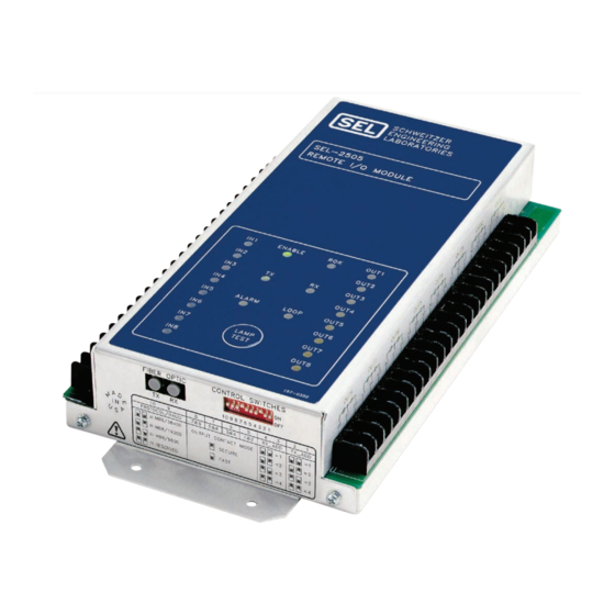
SEL-2505 Remote I/O Module
Instruction Manual
Features, Benefits, and Applications
The SEL-2505 is a remote I/O module
that has eight contact inputs and eight
contact outputs. The status of these
inputs and outputs are communicated
between the SEL-2505 and host device
using M
B
™ communica-
IRRORED
ITS
tions over a dedicated fiber-optic port.
Each contact input controls one of the
eight M
B
transmit bits,
IRRORED
ITS
while each of the eight received
M
B
controls a Form C
IRRORED
ITS
output contact. Use the transmitted
contact input status for control and
indication of a remote device.
Communications Ability
helps you simplify and
improve existing or new
installations.
Add bus protection using
existing relay contact
inputs and outputs.
Add simple pilot
communications to existing two- or three-terminal line applications.
Isolate relay and breaker dc supplies for breaker failure trip distribution schemes.
Replace control wiring to outside cabinets with fiber to reduce dc ground exposure.
Add local or remote trip and close coil monitoring capabilities.
Compact Size permits panel-mount replacement of existing auxiliary relays.
Self-Testing increases reliability of auxiliary relay functions.
Simple Diagnostics consisting of 22 LEDs that indicate contact input, output, channel, and
device status.
Fiber Optics and Channel Monitoring increase scheme security.
Three Models provide a wide range of applicable communication paths: 650 nm multimode
fiber for communications paths ≤ 500 m, 850 nm multimode fiber for paths ≤ 15 km, or 1300 nm
single-mode fiber for paths ≤ 80 km.
Fast Operating Speed compares with high-speed auxiliary relays.
Date Code 20010214
SEL-2505 Remote I/O Module
Advertisement
Table of Contents

Summary of Contents for Sel SEL-2505
- Page 1 SEL-2505 Remote I/O Module Instruction Manual Features, Benefits, and Applications The SEL-2505 is a remote I/O module that has eight contact inputs and eight contact outputs. The status of these inputs and outputs are communicated between the SEL-2505 and host device using M ™...
-
Page 2: Product Overview
Product Overview Figure 1 shows the functional overview of the SEL-2505. The SEL-2505 is an excellent auxiliary relay or a simple way of expanding the number of I/O points available in a system of relays. It is superior to hard-wiring relays together through electromechanical or static auxiliary relays, because you can now monitor the performance of the communication channel. - Page 3 Interface Provide a migration path from electromechanical Digital relays to M IRRORED Communications relays. Network Digital SEL-2505 Network 2800 Relay Interface Figure 4 Interface Relays with M to Relays Without. IRRORED SEL-2505 Remote I/O Module Date Code 20010214...
- Page 4 Figure 5 Reduce Wiring From Control House to Outdoor Cabinets. Example Distribution Figure 6 shows an SEL-2505 application using existing distribution relays and a SEL-2100 Protection Logic Processor to provide bus and Bus Protection: line protection for the radial system. When the overcurrent elements of...
-
Page 5: Functional Description
If a Receive M (RMB) is a logical one for the IRRORED number of message frames set by SW5 – 8, the SEL-2505 asserts the corresponding output contact. If an RMB is a logical 0 for the number of message frames set by SW5 –... -
Page 6: Configuring The Sel-2505
Configuring the SEL-2505 Configuring the SEL-2505 The SEL-2505 uses a ten-position dip switch to set the TX and RX addresses, to determine the number of received correct consecutive messages for output contact control, and to program the baud rate of the communications (see Table 2 on page 7). - Page 7 4. The transmit address of the local device must match the receive address of the remote device. If your relay does not have MB8 protocol, contact SEL for a firmware upgrade. The following examples show how to configure the SEL-351, SEL-321, and the SEL-2100 to operate with the SEL-2505.
-
Page 8: Testing The Sel-2505
Examples include an SEL-2505, SEL-2100, or a relay with M IRRORED protocol and the appropriate fiber-optic transducer. The following test procedure assumes you are using another SEL-2505 as the remote communicating device. The test procedure for other communicating devices is similar: Step 1. -
Page 9: Sel-2505 Operating Time Performance Diagram
ALARM contact should open and the ALARM LED should extinguish. Step 6. Apply rated voltage to IN1 on one device. The IN1 LED should illuminate on this device. On the other SEL-2505, the OUT1 contact should close and OUT1 LED should illuminate. -
Page 10: Mechanical Diagram
Mechanical Diagram Mechanical Diagram 12.50" (317.5 mm) 6.50" 2.50" (165.1 mm) (63.5 mm) 11.20" (284.5 mm) 2.175" (55.25 mm) 13.33" (338.6 mm) Figure 10 SEL-2505 Dimensions and Drill Diagram. SEL-2505 Remote I/O Module Date Code 20010214... -
Page 11: Specifications
Contact Input Update Rate ISO: Module is designed and manufactured Rated: 48/125 Vdc to an ISO-9001 certified quality program. 2 ms or 125 Vac CE Mark. Range: 36–200 Vdc or 85–140 Vac Burden: <5 W SEL-2505 Remote I/O Module Date Code 20010214... - Page 12 The information in this manual is furnished for informational use only and is subject to change without notice. The English language manual is the only approved SEL manual. ã 2000, 2001 Schweitzer Engineering Laboratories. All rights reserved.
Need help?
Do you have a question about the SEL-2505 and is the answer not in the manual?
Questions and answers