
Related Manuals for Scanlab RTC 4

Summary of Contents for Scanlab RTC 4
- Page 1 Installation and Operation ® The RTC 4 PC Interface Board for Real Time Control of Scan Heads and Lasers ® 4 PC Interface Board July 7, 2006 Rev. 1.3 e...
- Page 2 (Doc. Rev. 1.3 e - July 7, 2006) SCANLAB reserves the right to change the information in this document without notice. No part of this manual may be processed, reproduced or distributed in any form (photocopy, print, microfilm or by any other means), electronic or mechanical, for any purpose without the written permission of SCANLAB.
-
Page 3: Table Of Contents
Contents 1 Delivered Product ..........................6 1.1 Package Contents ........................6 1.2 Manufacturer ..........................6 1.3 About This Operating Manual ....................6 2 Product Overview ..........................7 2.1 Intended Use ..........................7 2.2 System Requirements ........................ 7 2.3 Board Dimensions And Layout ....................8 ®... - Page 4 5 Advanced Programming ........................40 5.1 Coordinate Transformations ....................40 5.2 Wobbel Function ........................41 5.3 Using Two Different Correction Files ..................42 Double Scan Head Configuration ..................42 Using Two Correction Files In A Single Scan Head System ..........42 ®...
- Page 5 2 Commands ..............125 11 Troubleshooting ..........................128 12 Customer Service ........................... 129 12.1 Servicing and Repairs ......................129 12.2 Warranty ..........................129 12.3 Contacting SCANLAB ......................129 12.4 Product Disposal ........................129 13 Technical Specifications ......................... 130 ® 4 PC Interface Board Rev.
-
Page 6: Delivered Product
Check the package for damage and confirm that are any questions regarding the contents of this all parts have been delivered. If anything is manual, please contact SCANLAB (see previous missing, please contact SCANLAB. section). Keep the packaging, including the antistatic bag Keep the manual available for servicing, repairs and ®... -
Page 7: Product Overview
Extension Board is to be used. double scan head control and runtime image SCANLAB offers additional PCI slot covers with D-SUB transformations. connectors for the following options: The included software driver provides an extensive •... -
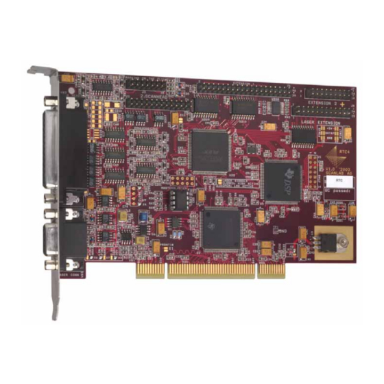
Page 8: Board Dimensions And Layout
2.3 Board Dimensions And Layout 160 mm MARKING ON THE FLY EXTENSION 1 EXTENSION 2 2. SCANHEAD LASER EXTENSION X8 X9 X6 X7 X3 PCI CONNECTOR Legend VB2 ....Primary scan head connector (D-SUB 25-pin female) VB3 . - Page 9 ® Optionally, the RTC 4 PC interface board can be delivered with an optical data interface. 160 mm MARKING ON THE FLY EXTENSION 1 EXTENSION 2 LASER EXTENSION U212 U214 X8 X9 U213 U211 X6 X7 X3 PCI CONNECTOR Legend U213/U211 .
-
Page 10: Notes For Rtc ® 3 Users
® 2.4 Notes For RTC 3 Users Changes in the Command Set New Commands ® This section summarizes how the RTC 4’s hardware ® and software differ from that of the RTC 3 PC • The new Arc Commands (see page 15) support ®... -
Page 11: Safety During Installation And Operation
Otherwise there is the danger of uncontrolled deflection of the laser beam. • Carefully check your application program before SCANLAB recommends the use of a shutter running it. Programming errors can cause a to prevent uncontrolled emission of laser break down of the system. -
Page 12: Principle Of Operation
Principle Of Operation 4.1 Software Concept List Commands And Control Commands Figure 3 shows a simple laser marking sample ® The RTC 4 command set consists of The image is made up of straight line segments or control commands and list commands. ®... -
Page 13: List Handling
List Handling Repeating Output Alternatively, continuous data transfer can be The command set_start_list (see page 116) opens a achieved by alternately repeating output of the two list buffer for writing. After finishing the data input, lists: the list must be closed with the command Load and close the two lists. -
Page 14: Synchronization Of Processing
START Signal Synchronization Of Processing Before the /START input can be used, it has to be The command set_wait (see page 118) makes it enabled with the command set_control_mode (see possible to set wait markers (break points) within a page 103). -
Page 15: Scan Head And Laser Control
The X component of a vector is split up into microsteps. (1) The coordinates must be specified as digital control values (without units). To avoid confusion with coordinates in [mm], SCANLAB uses the expression “coordinate values [in Bits]”. ® 4 PC Interface Board Rev. -
Page 16: Delays
The length ∆s of each microstep is 4.3 Delays ∆s = v · ∆t, The timing of the scan head and laser control signals where v is the current jump speed (marking speed). must be compatible with the dynamic behavior of the The output period ∆t of the position update is usually scan system, i.e. -
Page 17: Scanner Delays
LaserOn Delay Scanner Delays The LaserOn delay defines the moment when the ® 4 turns on the laser. LaserOn delay is automati- • There are three different types of scanner delays: cally inserted at the start of a mark or arc command jump delay, mark delay and polygon delay. - Page 18 Variable Jump Delay During a jump vector, the laser focus (output position) usually moves with a constant linear velocity, the jump speed. Since the jump speed is the same for each jump vector, a constant jump delay is required for settling of the mirrors. However, if a jump vector is very short, the scanners might not reach the full jump speed during the jump because of the inertia of the mirrors.
- Page 19 Mark Delay Although the marking speed is usually lower than the jump speed, a lag between the set position and LaserOn LaserOff Delay Delay the real position occurs not only during a jump, but also during a mark or arc command. To make sure that the scanners reach the final set position properly before the next command ®...
- Page 20 Polygon Delay The mark delay and the polygon delay can be set ® independently. In addition, the RTC 4 is able to vary Between two successive mark or arc commands, the length of the polygon delay, depending on the there is no need for a complete stop of the scanners. angle between two marking vectors or the tangents Therefore the mark delay between two successive of the arcs.
- Page 21 Variable Polygon Delay Edgelevel A variable polygon delay mode can be activated via Figure 9 shows that the variable polygon delay becomes quite long if the angle φ is close to 180°. the command set_delay_mode (page 104). In this ® mode, the RTC 4 allows varying the length of the This might lead to burn-in effects in the sharp corners...
- Page 22 LaserOn LaserOff LaserOn LaserOff Delay Delay Delay Delay Last Mark Time Mark Mark Command Command Command In This Polyline Legend 1 Variable polygon delay, shorter than the specified edgelevel. 2 Variable polygon delay, longer than the edgelevel. The laser is turned off between the two mark or arc commands. 3 Mark delay.
- Page 23 Customizing The Variable Polygon Delay Notes • Each instruction must be in a separate line. The command load_varpolydelay(FileName, X) loads a table for the scaling function scale(φ) from an • Empty lines are ignored. ASCII text file (with the filename extension *.STB). •...
-
Page 24: Notes On Optimizing The Delays
Notes On Optimizing The Delays The reasons for the two constraints can be understood as follows: The delays have to be set with the commands (1) Consider a very short mark command. set_scanner_delays and set_laser_delays. The If the sum of the marking time and the LaserOff delay is delays have to be appropriate for the defined jump shorter than the LaserOn delay, the LaserOff delay will speed and the marking speed. - Page 25 + LOnD > LOffD Otherwise, it could occur that the laser is off for the rest of the polyline. SCANLAB recommends to use the auto_change command for automatic list change or to add a small software delay of the size (LOffD - LOnD - polygonD) previously to starting the second list.
- Page 26 Optimizing The Delays The following figures show the various effects of non-optimized delays on the letters "RTC". LaserOn Delay too short Mark Mark Mark At the beginning of a mark vector the laser is switched on, even Mark though the mirrors have not yet reached the necessary angular velocity.
- Page 27 Jump Delay too short Mark Mark Mark After a jump, the first mark vector has already started although the Mark scanners have not yet settled. A running-in oscillation (overshoot) will be visible. Mark Jump Delay too long There are no visible effects if the jump delay is too long.
- Page 28 Polygon Delay too short Mark Mark Mark The subsequent mark command in a polyline is already executing, Mark although the mirrors have not yet reached the end position of the preceding mark vector. The corners of the polyline are rounded off. Mark Polygon Delay too long Mark...
-
Page 29: Image Field Size
4.4 Image Field Size SCANLAB provides a rounded value for the cali- bration factor K. This value is slightly larger than, but close to, the theoretical value. Figure 12 shows the reference system for the image ® field which is used by the RTC 4. -
Page 30: Image Field Correction
4.5 Image Field Correction The deflection of a laser beam with a two-mirror system results in three effects: (1) The arrangement of the mirrors leads to a certain distortion of the image field – see figure 14 on page This distortion arises from the fact that the distance between mirror 1 and the image field depends on the size of the scan angles of mirror 1 and mirror 2. - Page 31 "Microsteps", page 15.) • A direct proportionality between scan angle and By default, SCANLAB creates an individual correction distance in the image field is obtained. table for every delivered system. It is stored in a file • Additionally, the focus lies on a flat surface.
-
Page 32: Laser Control
4.6 Laser Control Notes: • The command set_laser_mode must be called ® ® The RTC 4 provides several laser control signals during initializing the RTC 4 for selecting the with programmable pulse width and frequency. laser control mode. After the initialization the These signals can be used for controlling various laser control is activated. -
Page 33: Co 2 Mode
Mode The command set_laser_timing is a list command, i.e. it can be used anywhere in a list. This allows, for The command set_laser_mode(0) selects the CO instance, changing the laser power at any time within laser mode. In this mode, the following laser signals a list. -
Page 34: Yag Modes
YAG Modes The length of the FirstPulseKiller signal is set with the command set_firstpulse_killer With the commands set_laser_mode(1), set_firstpulse_killer_list (see page 105). set_laser_mode(2) or set_laser_mode(3) one can choose between three different YAG laser control Differences Between YAG Modes 1 - 3 ®... -
Page 35: Softstart Mode
Softstart Mode For some applications it’s important to control the laser intensity at the beginning of a marking process. SCANLAB provides a convenient solution in the form of the softstart mode, which can be used for all laser modes. With the command... - Page 36 YAG Modes 1-3 End of Vector Start of Vector Vector Output LaserOn LaserOff Delay Delay LASERON Q-Switch Q-Switch Period Pulse Width LASER1 (Q-Switch) FirstPulseKiller Length YAG 1 LASER2 (FirstPulseKiller) Q-Switch Q-Switch Pulse Width Period LASER1 (Q-Switch) FirstPulseKiller Length YAG 2 LASER2 (FirstPulseKiller) Q-Switch...
-
Page 37: Laser Mode 4
Laser Mode 4 The FirstPulseKiller signal is started together with the LASERON signal. The length of the FirstPulseKiller The command set_laser_mode(4) selects the laser signal is set with the command set_firstpulse_killer mode 4. In this mode, the following laser signals are set_firstpulse_killer_list (see page 105). -
Page 38: Status Monitoring And Diagnostics
• the current value of the LASERON signal with the XY2-100 Protocol. Thus, the intelliSCAN ® can also be operated via all SCANLAB RTC • the current cartesian output values (coordinate interface boards to thereby obtain the standard func- transformations defined by set_matrix, tionality typical of traditional SCANLAB scan heads. -
Page 39: Querying Data
Querying Data ® Data received by the RTC 4 can be read asynchronously at any time via the commands get_value get_head_status or synchronously via the command set_trigger (see "Status Monitoring and Diagnostics", page 38 and the corresponding command references). Please note that switching of the data source is followed by a short (serial transmission-related) delay before the first data is transmitted. -
Page 40: Advanced Programming
Advanced Programming 5.1 Coordinate Transformations 2. Scaling by the factors ® The RTC 4 has the ability to transform the output – coordinates by the following linear transformation – for each vector defined with a jump, mark or arc command: 3. -
Page 41: Wobbel Function
5.2 Wobbel Function The wobbel function allows varying the line width during laser marking. Basically, a circular movement is added to the regular, linear movement of the output position, resulting in a spiral movement of the laser focus in the image field. -
Page 42: Using Two Different Correction Files
5.3 Using Two Different Correction Files Double Scan Head Configuration Using Two Correction Files In A Single Scan Head System ® The RTC 4 (2D version) can store two different correction files at the same time. For two scan heads It can also be useful to work with two different ®... -
Page 43: Using Multiple Rtc ® 4 Boards In One Computer
® 5.4 Using Multiple RTC 4 Boards 3. sn_1 := n_get_serial_number(1) In One Computer returns the serial number of board #1. (B) Sequential Programming ® The RTC 4 driver DLL supports simultaneous control ® of up to eight RTC 4 boards in one PC. For sequential programming, the command select_rtc (see page 103) activates one of the... -
Page 44: Circular Queue Mode
5.5 Circular Queue Mode Circular Queue Control If it is necessary, the command stop_execution Instead of using the two list buffers as described in be called to immediately stop execution of the ® chapter 4.1, the RTC 4 memory can also be used as circular queue. -
Page 45: Structured Programming
5.6 Structured Programming ® The command set of the RTC 4 includes a number of List Jumps list commands for controlling program flow: The command set_list_jump (see page 109) defines • set_list_jump a jump to the specified address. During execution, •... -
Page 46: Programming Examples
Programming Examples The following programming examples are written in PASCAL. (1) Confirm a signal: set_start_list(1); set_io_cond_list(0, 0, 1); // set bit #0 of the 16-bit digital output port list_jump_cond(0, 1, get_input_pointer); // loop until the signal is confirmed // (i.e. bit #0 of the digital input turns HIGH) clear_io_cond_list(0, 0, 1);... -
Page 47: Scanning Raster Images (Bitmaps)
5.7 Scanning Raster Images (Bitmaps) The vector commands described in chapter 4.2 Data Input (Optional) intended for scanning vector based images. However, ® If the RTC 4 is used together with an optional I/O ® the RTC 4 also allows reproduction of raster images Extension Board, the command set_pixel also allows... - Page 48 Timing If you need the LASERON signal and the ANALOG OUT2 ® signal, then you have the possibility (with an RTC including the Processing-on-the-fly option only) of setting Figure 20 shows the pixel output timing diagram. jumper X7 to position 1-2 and taking the signal Each LASERON pulse is preceded by a LaserOn delay.
- Page 49 Scanner Control Mode 1 In Mode 1, each image line is treated like a normal ® The RTC 4 supports two different modes for vector. That means the movement is split up into a scanning raster image lines. The two modes differ in number of microsteps.
-
Page 50: Timed Jump And Mark Commands
Laser Control The ANALOG OUT2 port is optionally available at the 9-pin D-SUB Laser Connector. The output Black-And-White Images range is 0 V … 10 V. Please refer to the section "Laser / Analog Output Ports (9-Pin Laser Connector)", For black-and-white images, the pulse width page will be set either to zero ("black"... -
Page 51: Automatic Self-Calibration
For applications that are subjected to unavoidable environmental fluctua- tions, but nevertheless require high long-term repeatability, SCANLAB provides scan heads with automatic self-calibration (optional for apertures ≥ 14 mm). Scan heads delivered with this option have an internal reference sensor system. -
Page 52: Electrical Connections
ANALOG OUT 1 signal with +5 V, then the maximum current load at pin (4) of the laser connector is 100 Further input and output ports are provided by the ® optional RTC 4 I/O Extension Board from SCANLAB (see "Options", page 57). ®... -
Page 53: Laser Extension Connector
6.2 Laser Extension Connector 8-Bit Digital Output Port The buffered 8-bit digital output port (TTL level) is The 26-pin connector LASER EXTENSION on the intended for YAG lasers with a digital lamp current ® 4 board provides a buffered 8-bit digital output control. -
Page 54: Primary Scan Head Connector
The pin out of this connector is shown in figure 26 on page The signals on this connector are optional and must be enabled by SCANLAB. Please contact SCANLAB for further information. Also see chapter 7 "Options", page... -
Page 55: Data Cable
Some scan heads use a single connector to provide both the power supply voltages and the data signals. ® For these scan heads, SCANLAB recommends imple- To connect the scan head to the RTC 4, a data cable menting a cabling solution that allows the use of is required. -
Page 56: Optical Data Interface (Optional)
The optical fiber cable is not included in the package. read_io_port get_io_status commands read SCANLAB recommends use of a 1 mm diameter the current values of the digital input or output ports. duplex polymer optical fiber (POF) cable with a set_io_cond_list clear_io_cond_list maximum length of 30 m. -
Page 57: Options
• Controlling the Third Axis of a 3-Axis System The following options are available for the RTC Please contact SCANLAB for further information. The optional third data channel can be used, for example, for controlling a varioSCAN module in a 3-axis scan system. -
Page 58: Installation And Start-Up
Installation And Start-Up ® 8.1 Jumper Settings Overview Installation of the RTC 4 consists of the following steps: ® ® The factory settings for the RTC 4 jumpers are listed (1) configuring the RTC 4 jumpers on the supplement at the end of this manual. ®... -
Page 59: Changing The Jumper Settings
8.2 Changing The Jumper Laser / Analog Output Ports Settings (9-Pin Laser Connector) The signals at pins (2) and (4) of the 9-pin laser output port connector (see figure 30 on Caution! page 59) must be selected via jumpers X6, X7 and X3. -
Page 60: Digital Output Port (Laser Extension Connector)
Digital Output Port Examples (Laser Extension Connector) • If the L7 bit is assigned to pin (15), the full 8-bit output value is available on the output port The 8-bit digital output port is available via the (odd numbered pins (1) to (15) of the LASER EXTENSION connector –... -
Page 61: Installing The Drivers
8.4 Installing the Drivers 8.5 Start-Up and Functionality Test ® For installing RTC 4 drivers for WINDOWS XP and WINDOWS 2000 proceed as follows: Danger! Note ® • Always turn on the RTC 4 and the power ® • RTC 4 boards cannot be used simultaneously supply for the scan head first before turning ®... -
Page 62: Software
7 "Options", page do not overwrite customized correction files!). Make sure to use only the commands supported SCANLAB recommends storing these files in the ® by your version of the RTC 4. Please refer to the directory in which the application software will descriptions of the individual commands in be started. -
Page 63: Initializing The Rtc ® 4
® 9.3 Initializing the RTC In C, you can choose either implicit linking – also ® At the beginning of each RTC 4 application program, known as static load or load-time dynamic linking – you need to perform the following steps: or explicit linking –... -
Page 64: Demo Programs
9.4 Demo Programs The samples are written in the C language. They ® show the necessary calling sequences of the RTC ® commands, which you can easily translate into your The RTC 4 software package contains six different preferred programming language. program code samples (file DEMO.ZIP). - Page 65 A console application for marking a square and a triangle 0, R, by using a CO2 laser -R, 0 // Author Bernhard Schrems, SCANLAB AG #define POLYGONSIZE(figure) (sizeof(figure)/sizeof(polygon)) // Comment Besides demonstrating of how to initialize the RTC4 and how to void ErrorMessage(short ErrorCode);...
- Page 66 set_laser_delays(100, // laser on delay in microseconds void draw(polygon *figure, unsigned size) { 100); // laser off delay in microseconds unsigned short busy, position; set_jump_speed(1000.0); // jump speed in bits per milliseconds unsigned set_mark_speed(250.0); // marking speed in bits per milliseconds set_end_of_list();...
- Page 67 WavePoints; // Author short Ch1[MaxWavePoints], Ch2[MaxWavePoints]; Gerald Schmid, SCANLAB AG // Comment // Initialize: load correction and program file Besides demonstrating of how to initialize the RTC4 and how to ErrorCode = load_correction_file("cor_1to1.ctb", perform marking, this application also shows how to implicitly // table;...
- Page 68 (void)getch(); jump_abs(-380, -570);// N printf("\n\n"); mark_abs(-380, 570); mark_abs(380, -570); // mark "SCANLAB", record the measured position bend and transfer it to the PC mark_abs(380, 570); set_laser_mode(1);// set YAG mode 1 jump_abs(760, 570);// L mark_abs(760, -570); set_start_list(1);// timing, delay and speed preset mark_abs(1520, -570);...
-
Page 69: Commands And Functions
10 Commands And Functions 10.1 Overview The tables on page 70 page 71 show the ® complete RTC 4 command set (control commands and list commands; also see chapter 4.1 "Software Concept", page 12). The commands are listed according to their intended use. The page numbers refer to chapter 10.3 "Command Set". -
Page 70: Control Commands
Control Commands Initialization And Field Correction List Handling And Status (n_) load_program_file ........96 (n_) set_start_list ........... 116 (n_) load_correction_file ......... 95 (n_) execute_list ..........81 (n_) select_cor_table ........102 (n_) stop_execution ........119 (n_) load_varpolydelay ........97 (n_) stop_list ..........119 (n_) dsp_start ........... -
Page 71: List Commands
Other Control Commands get_dll_version ......... 82 (n_) get_hex_version ........83 (n_) get_rtc_version ......... 84 (n_) get_serial_number ........85 (n_) home_position ......... 89 get_hi_data ..........83 (n_) get_time ........... 86 (n_) set_piso_control ........111 (n_) auto_cal ............ 74 List Commands Vector Commands Setting The Scanner Parameters (n_) jump_abs .......... -
Page 72: Data Types
10.2 Data Types The following table defines the formats and ranges of the different data types used by the ® 4 commands: Data Format Range Pascal Basic 64-bit IEEE floating point format double double double signed 16-bit value [–32768; +32767] smallint short integer... -
Page 73: Command Set
10.3 Command Set All commands are arranged in alphabetical order. List Command arc_abs Function marking along the specified circular arc starting at the current position Parameters absolute coordinates of the arc center in bits as signed 16-bit values arc angle in ° [–360.0° … +360.0°] as 64-bit IEEE floating point value angle (positive angle values correspond to clockwise angles) Integration... - Page 74 Ctrl Command auto_cal Function starts or stops automatic self-calibration or re-calibrates the scan head (requires a scan head with automatic self-calibration option) Parameters = 1: calibration of scan head A (primary scan head connector) head = 2: calibration of scan head B (secondary scan head connector) Control parameter (unsigned 16-bit value): command = 0:...
- Page 75 Ctrl Command auto_change Function activates an automatic list change Integration Pascal: procedure auto_change; void auto_change(void); Basic: sub auto_change() Comments • The auto_change command should only be used when working with two lists (up to 4000 commands each). This command should only be used if a list is currently executing, or if it has already executed.
- Page 76 List Command clear_io_cond_list Function clears the bits of the 16-bit digital output port that are set (=1) in mask_clear, if the current IOvalue at the digital input port meets the following condition: ((IOvalue AND mask_1) = mask_1) AND (((not IOvalue) AND mask_0) = mask_0) (i.e.
- Page 77 Ctrl Command control_command ® Function sends a control command to intelliSCAN scan systems Parameter head = 1: Head A = 2: Head B axis = 1: X axis (STATUS channel, galvanometer scanner 2) = 2: Y axis (STATUS1 channel, galvanometer scanner 1) = 3: Z axis data...
- Page 78 Ctrl Command control_command 0528 Flags B15 ... B0 [0 ... 65535]: Current operational state Bit #15 (MSB) = 1: Galvanometer scanner’s output stage is on Bit #14 = 1: Galvo heater’s output stage is on Bit #13 = 1: Internal voltages normal Bit #12 = 1: Position error within normal range...
- Page 79 Ctrl Command control_command procedure control_command(head, axis, data: word); Integration Pascal: void control_command(unsigned short head, unsigned short axis, unsigned short data); sub control_command(ByVal head As Integer, ByVal axis As Integer, ByVal data Basic: As Integer) ® Comments • The control_command command can only be used in conjunction with intelliSCAN scan systems.
- Page 80 Ctrl Command disable_laser ® Function deactivates the laser control of the RTC Integration Pascal: procedure disable_laser; void disable_laser(void); Basic: sub disable_laser() Comments • This command disables the laser signals LASER1, LASER2 and LASERON. That means pins (1), (2) (LASERON) and (3) of the 9-pin laser connector and pins (19) and (22) of the LASER EXTENSION connector (on-board) are static.
- Page 81 Ctrl Command execute_at_pointer ® Function starts list execution at the specified address in the RTC 4 list buffer. Also see chapter 5.6 "Structured Programming", page Parameter address of the first list command to be executed (unsigned 16-bit value). pointer Allowed range: [0 … 7999] Integration Pascal: procedure execute_at_pointer(pointer: word);...
- Page 82 Ctrl Command get_dll_version ® Function returns the version number of the RTC 4 driver DLL Result DLL version number as an unsigned 16-bit value Integration Pascal: function get_dll_version: word; unsigned short get_dll_version(void); Basic: function get_dll_version()% ® Comments • The RTC 4 DLL version numbers are in the range 400-499.
- Page 83 Ctrl Command get_hex_version ® Function returns the version number of the RTC 4 software (program file) ® Result 4 software version number as an unsigned 16-bit value Integration Pascal: function get_hex_version: word; unsigned short get_hex_version(void); Basic: function get_hex_version()% ® Comments •...
- Page 84 Ctrl Command get_io_status Function returns the current state of the 16-bit digital output port on the “EXTENSION 1” connector Result unsigned 16-bit value (DIGITAL_OUT0 … DIGITAL_OUT15) Integration Pascal: function get_io_status: word; unsigned short get_io_status(void); Basic: function get_io_status()% Comments • This command is conceived of for use in combination with the commands set_io_cond_list and clear_io_cond_list.
- Page 85 Ctrl Command get_serial_number ® Function returns the individual serial number of the RTC 4 board ® Result 4 serial number as an unsigned 16-bit value Integration Pascal: function get_serial_number: word; unsigned short get_serial_number(void); Basic: function get_serial_number()% ® Comments • The command is helpful when using several RTC 4 boards in one computer.
- Page 86 Ctrl Command get_status Function returns the current status of list execution true ( ≠ 0 ) : a list is executing at the moment Result busy false ( = 0 ) : no list is executing at the moment pointer to the command which is executing at the moment position 0 ≤...
- Page 87 Ctrl Command get_value Function reads the current value of the specified signal Parameter specified signal represented by an unsigned 16-bit value: signal = 0: LASERON signal (1 = Laser On, 0 = Laser Off) = 1: StatusAX (X-axis status channel of head A) = 2: StatusAY (Y-axis status channel of head A) = 3:...
- Page 88 Ctrl Command get_wait_status ® Function returns the wait state of the RTC Result wait state as an unsigned 16-bit value Integration Pascal: function get_wait_status: word; unsigned short get_wait_status(void); Basic: function get_wait_status()% Comments • If processing has stopped at a wait marker, the command get_wait_status returns the number of this marker.
- Page 89 Ctrl Command goto_xy Function direct jump to the specified position Parameters coordinates of the jump position in bits as signed 16-bit values xpos, ypos Integration Pascal: procedure goto_xy(xpos, ypos: smallint); void goto_xy(short xpos, short ypos); Basic: sub goto_xy(ByVal xpos%, ByVal ypos%) Comments •...
- Page 90 List Command jump_abs Function fast movement of the mirrors ("jump") to the specified position Parameters absolute coordinates of the vector end point in bits as signed 16-bit values. xval, yval Integration Pascal: procedure jump_abs(xval, yval: smallint); void jump_abs(short xval, short yval); Basic: sub jump_abs(ByVal xval%, ByVal yval%) Comments...
- Page 91 List Command laser_on_list Function turns on the laser for a specified time interval time interval in bits as an unsigned 16-bit value. 1 bit equals 10 µs. Parameter delay Allowed range: 0 ≤ delay ≤ 65500 Integration Pascal: procedure laser_on_list(delay: word); void laser_on_list(unsigned short delay);...
- Page 92 Ctrl Command laser_signal_on Function turns on the laser immediately Integration Pascal: procedure laser_signal_on; void laser_signal_on(void); Basic: sub laser_signal_on() Comments • The command is intended for turning on the laser directly, e.g. for alignment purposes. • Prior to calling the command laser_signal_on, the period and pulse width of the outgoing signal must be set via the list command set_laser_timing.
- Page 93 List Command list_call_cond Function Conditional subroutine call: During execution of a list, this command causes a jump to a subroutine at the specified list buffer address [0 … 7999], if the current IOvalue at the 16-bit digital input port meets the following condition: ((IOvalue AND mask_1) = mask_1) AND (((not IOvalue) AND mask_0) = mask_0) (i.e.
- Page 94 List Command list_nop Function inserts a null operation (no operation) into the list buffer Integration Pascal: procedure list_nop; void list_nop(void); Basic: sub list_nop() • Null operations serve as place markers. The execution of a null operation needs 10 µs. Comments List Command list_return Function terminates a list subroutine and jumps to the command following the...
- Page 95 Ctrl Command load_correction_file ® Function loads the specified field correction file into RTC 4 memory (as table #1 or #2) and performs additional scaling, rotation and translation of the correction file Parameters name of the correction file as a pointer to a null-terminated ANSI string FileName cor_table determines whether the file shall be stored as correction table #1 or #2 (see command...
- Page 96 Ctrl Command load_program_file ® Function loads the specified program file into RTC 4 memory Parameter name of the program file as a pointer to a null-terminated ANSI string FileName Result error code as a signed 16-bit value: Value Description Success. File error.
- Page 97 Ctrl Command load_varpolydelay ® Function loads a table for the variable polygon delay into the RTC See the section "Customizing The Variable Polygon Delay" on page Parameters name of the data file (with extension *.STB) as a pointer to a null- STBFileName terminated ANSI string.
- Page 98 List Command long_delay Function stops execution of the list for the specified time delay time in bits as an unsigned 16-bit value. 1 bit equals 10 µs. Parameter delay Allowed range: 0 ≤ delay ≤ 65500. Integration Pascal: procedure long_delay(delay: word); void long_delay(unsigned short delay);...
- Page 99 Ctrl Command measurement_status Function returns the status of a measurement session started via set_trigger true ( ≠ 0 ) : a measurement session is currently in progress Result busy false ( = 0 ) : no measurement session is currently in progress ®...
- Page 100 Ctrl Command read_pixel_ad Function returns the ADC value that was obtained at a pixel position during the output of a raster image line Parameter list pointer to the corresponding set_pixel command [0 … 7999] ® Result 10-bit output value from the analog input channel (on the RTC 4 I/O Extension Board) which was specified with the set_pixel...
- Page 101 Ctrl Command release_wait Function resumes execution of a list that was interrupted by a set_wait command Result wait state as an unsigned 16-bit value Integration Pascal: procedure release_wait; void release_wait(void); Basic: sub release_wait() ® Comments • The command release_wait can only be used if the RTC 4 is actually in a wait state (i.e.
- Page 102 Ctrl Command select_cor_table Function assigns the previously loaded correction tables #1 and #2 to the scan head control ports Parameters = 0: turns off the signals for scan head A (primary scan head connector) head_a = 1: assigns correction table #1 to scan head A = 2: assigns correction table #2 to scan head A = 0:...
- Page 103 Ctrl Command select_rtc ® Function defines the active RTC 4 board in a multi-board system. See chapter 5.4, page ® Parameter number of the RTC 4 board CardNo Integration Pascal: procedure select_rtc(CardNo: word); void select_rtc(unsigned short CardNo); Basic: sub select_rtc(ByVal CardNo%) Comments •...
- Page 104 Ctrl Command set_delay_mode Function turns the variable polygon delay mode and the variable jump delay mode on or off Parameters All parameters must be unsigned 16-bit values. Parameter Allowed Values Description > 0 Enables the variable polygon delay mode. See page varpoly Disables the variable polygon delay mode.
- Page 105 List Command set_extstartpos_list Function defines the start position (list buffer address) of the list to be executed by the next external start signal Parameter list pointer to the start address of the list [0 … 7999] position Integration Pascal: procedure set_extstartpos_list(position: word); void set_extstartpos_list(unsigned short position);...
- Page 106 Ctrl Command set_input_pointer ® Function sets the list input pointer to the specified address in the RTC 4 list buffer. The next list command will be stored at this address. Also see chapter 5.6 "Structured Programming", page Parameter list input pointer [0 … 7999] as unsigned 16-bit value pointer Integration Pascal:...
- Page 107 List Command set_jump_speed Function defines the jump speed for the following vector commands Parameter jump speed in bits per ms (64-bit IEEE floating point value) jump_speed Allowed range: [1 … 50000] Integration Pascal: procedure set_jump_speed(jump_speed: double); void set_jump_speed(double jump_speed); Basic: sub set_jump_speed(ByVal jump_speed#) Comments •...
- Page 108 Ctrl Command set_laser_mode ® Function selects the laser control mode of the RTC Parameter = 0: mode mode = 1: YAG mode 1 = 2: YAG mode 2 = 3: YAG mode 3 = 4: laser mode 4 Integration Pascal: procedure set_laser_mode(mode: word);...
- Page 109 List Command set_list_jump Function defines a jump to the specified list buffer address Parameter jump address [0 … 7999] as unsigned 16-bit value address Integration Pascal: procedure set_list_jump(address: word); void set_list_jump(unsigned short address); Basic: sub set_list_jump(ByVal address%) Comments • See chapter 5.6 "Structured Programming", page References list_call...
- Page 110 Ctrl Command set_matrix Function defines a (2 x 2) transformation matrix which will be used for all subsequent vector outputs. Parameters Matrix coefficients as 64-bit IEEE floating point values m11, m12, Allowed range: [ – 100 … 100] m21, m22 Integration Pascal: procedure set_matrix(m11, m12, m21, m22: double);...
- Page 111 Ctrl Command set_offset Function defines an offset in the X and Y directions which will be added to all subsequent vector outputs. Parameters offset in bits x_offset, Allowed range: [ – 32768 …+32767] y_offset Integration Pascal: procedure set_offset(x_offset, y_offset: smallint); void set_offset(short x_offset, short y_offset);...
- Page 112 List Command set_pixel Function defines the output parameters (laser pulse width and ANALOG OUT2 value) for one pixel ® in an image line. In addition, one of the four analog input ports of the RTC 4 I/O Extension ® Board can be read during the output of the pixel (RTC 4 with I/O Extension Board only).
- Page 113 List Command set_pixel_line Function switches to the pixel output mode, defines various pixel output parameters and marks the beginning of a pixel line. Also see chapter 5.7 "Scanning Raster Images (Bitmaps)", page Parameters = 0: The laser focus "jumps" from one pixel to the next. pixel_mode = 1: The laser focus moves from one pixel to the next in small steps...
- Page 114 Ctrl Command set_softstart_level Function sets the softstart values. Parameters All parameters must be unsigned 16-bit values. Parameter Allowed Values Description 0 ... n index number of the softstart table value index 0 … 1023 for softstart mode = 1, 2, 11 and 12. Value 0 corresponds to 0 V; value level 1023 corresponds to 2.56 V (for jumper X3 position 1-2) or 10 V (for jumper X3 position 2-3).
- Page 115 Ctrl Command set_softstart_mode Function initializes the softstart mode. Parameters All parameters are unsigned 16-bit values. Parameter Allowed Values Description disables the softstart mode, but does not remove previously loaded mode softstart values. = 1, 11 enables the analog output signal ANALOG OUT1. = 2, 12 enables the analog output signal ANALOG OUT2.
- Page 116 Ctrl Command set_standby Function defines the output period and the pulse width of the stand-by pulses or – in Laser Mode 4 – the continuously-running laser signals. half of the stand-by output period in bits. 1 bit equals 1/8 µs. Parameters half_period Allowed range: [0 …...
- Page 117 List Command set_trigger Function starts measurement and storage of the specified signals measurement period [(1..65535) · 10 µs] as an unsigned 16-bit value Parameters sample- period The following signals (each represented by an unsigned 16-bit value) are signal1, specifiable for measurement channels 1 and 2: signal2 = 0: LASERON signal (1 = laser on, 0 = laser off)
- Page 118 List Command set_wait Function sets a wait marker (break point) in the list Parameter number of the wait marker as an unsigned 16-bit value [1 … 65535] wait_word Integration Pascal: function set_wait(wait_word: word); void set_wait(unsigned short wait_word); Basic: sub set_wait(ByVal wait_word%) Comments •...
- Page 119 Ctrl Command start_loop Function starts an alternately repeating output of the two lists Integration Pascal: procedure start_loop; void start_loop(void); Basic: sub start_loop() Comments • The command start_loop can only be called if the two lists are loaded and closed, and if one of the lists is executing at the moment.
- Page 120 List Command timed_jump_abs Function jump to the specified position in the image field using the specified duration Parameters absolute coordinates of the vector end point in bits as signed 16-bit values. xval, yval duration of the complete jump vector in microseconds time Allowed range: [10 …...
- Page 121 List Command timed_mark_abs Function marking vector to the specified position in the image field using the specified duration Parameters absolute coordinates of the vector end point in bits as signed 16-bit values. xval, yval duration of the complete mark vector in microseconds time Allowed range: [10 …...
- Page 122 Ctrl Command write_8bit_port Function writes an 8-bit value to the digital output port on the LASER EXTENSION connector Parameter output value for the digital output port as unsigned 16-bit value. value Allowed range: [0 … 255] Integration Pascal: procedure write_8bit_port(value: word); void write_8bit_port(unsigned short value);...
- Page 123 List Command write_da_2_list Function write_da_x_list Integration Pascal: procedure write_da_2_list(value: word); void write_da_2_list(unsigned short value); Basic: sub write_da_2_list(ByVal value%) Ctrl Command write_da_x ® Function writes a 10-bit value to one of the analog output ports of the RTC 4 or the ®...
- Page 124 List Command write_io_port_list Function same as write_io_port, but a list command Integration Pascal: procedure write_io_port_list(value: word); void write_io_port_list(unsigned short value); Basic: sub write_io_port_list(ByVal value%) References write_io_port Ctrl Command z_out ® Function sends a 16-bit value directly to the Z channel of the RTC (CHAN3;...
-
Page 125: Supported And Unsupported Rtc ® 2 Commands
10.4 Supported and Unsupported ® 2 Commands ® ® The RTC 4 emulates some RTC 2 commands for compatibility. Though these emulated commands ® can be used with the RTC 4, new application soft- ware should only use the commands described in chapter ®... - Page 126 List Command home_jump ® ® Support status This RTC 2 command is not supported by the RTC Replaced by home_position (see page 89) List Command laser_on ® ® Support status This RTC 2 command is not supported by the RTC Replaced by laser_on_list (see page 91) Ctrl Command load_cor (load correction file)
- Page 127 Ctrl Command set_co2_standby ® ® Support status This RTC 2 command is not supported by the RTC Replaced by set_standby (see page 116) List Command set_co2_standby_list ® ® Support status This RTC 2 command is not supported by the RTC Replaced by set_standby (see page 116) List Command set_delays...
-
Page 128: Troubleshooting
• Check the laser and scanner delays. "Notes On Optimizing The Delays", page Laser doesn’t switch off during • Check the laser and scanner delays. See page jump commands If the problems persist, please contact SCANLAB. ® 4 PC Interface Board Rev. 1.3 e 11 Troubleshooting... -
Page 129: Customer Service
12.4 Product Disposal • when the product has been damaged through ® The RTC 4 can be returned to SCANLAB for a fee to misuse or improper operation be properly disposed of. • for repairs not performed by SCANLAB ®... -
Page 130: Technical Specifications
13 Technical Specifications System Requirements Digital Input Port 16 bits IBM-compatible PC with PCI bus interface LOW level < 0.5 V Operating system Microsoft WINDOWS XP HIGH level 2.6 V … 24 V and WINDOWS 2000 Input resistance > 10 kΩ Minimum free space 105 mm The input signals are referenced to GND. - Page 131 Index get_hex_version ......... 83 get_hi_data ..........83 3-axis system ..........55, 57 get_input_pointer ........83 get_io_status ..........84 get_list_space ..........84 get_rtc_version .......... 84 analog output ports ......52, 59, 123 get_serial_number ........85 arc commands ..........12, 15 get_startstop_info ........85 arc_abs (command) ...........
- Page 132 EXTENSION 1 connector ........56 z_out_list ..........124 external control signals ....... 52, 103 connectors, pin-outs ........52–56 contacting SCANLAB ......... 129 continuous data transfer to scan head ....13 control commands ........12, 70 field distortion ..........30–31 control signals ............ 54 FirstPulseKiller signal ...........
- Page 133 get_serial_number (command) ......85 – during jump command ......18 get_startstop_info (command) ......85 – during mark command ......19 get_status (command) ........86 commands ........108, 116 get_time (command) ......... 86 lamp current ......... 34, 98 get_value (command) ........87 timing (CO mode) ........
- Page 134 – during jump command ......18 I/O extension board ........57 – during mark command ......19 optical data interface ......56, 57 SCANLAB, contacting ........129 optoelectronic couplers ......52, 57 scanner delays ........17–18, 113 Processing-on-the-fly ........57 select_cor_table (command) ......
- Page 135 initialization ..........63 write_io_port (command) ........ 123 stand-by pulses ........... 33, 116 write_io_port_list (command) ......124 start_loop (command) ........119 start-up ............11, 61 status monitoring and diagnostics ..... 38 XY2-100 Enhanced protocol ....... 38 status signals ..........54, 56 XY2-100 standard ......
- Page 136 Notes ® 4 PC Interface Board Rev. 1.3 e Notes...
Need help?
Do you have a question about the RTC 4 and is the answer not in the manual?
Questions and answers