Advertisement
ONLINE PRODUCT REGISTRATION: Register your MSD product online. Registering your product
will help if there is ever a warranty issue with your product and helps the MSD R&D team create
new products that you ask for! Go to www.msdperformance.com/registration.
Parts Included:
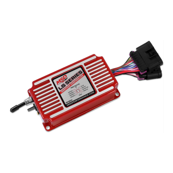
1 – LS Ignition Controller, PN 6014
1 – Main Wiring Harness
1 – Crank/Cam Pigtail 24x
1 – Crank/Cam Pigtail 58x
Optional Accessories (Purchased Separately):
LS Coolant Temp Sensor, GM PN 12608814
PN 2279 - 24x Crank/4x Cam
WARNING: During installation, disconnect the battery cables. When disconnecting, always re-
move the negative cable first and install it last.
Note: Solid core spark plug wires cannot be used with an MSD Ignition Control.
OPERATION
The MSD 6014 LS Ignition controller works with 24x/1x, 58x/4x and 58x/1x crank/cam configura-
tions. It auto detects the correct configuration based on the reluctor wheel pattern, so there is no
need to select one. It provides six pre-programmed (non-editable) timing tables for stock engines,
three customizable 3-D tables and one customizable timing plot. The desired table/plot is selected
on the fly using the rotary dial. The customizable tables and plot can be programmed via MSDView.
The LS Ignition controller includes a built-in 2.5 Bar MAP sensor that can be used with Naturally
Aspirated or boosted applications. This allows for timing advance or retard based on the intake
manifold pressure.
8Mb of internal data logging is also included so you can setup, record and review runs at the track.
Note: It is recommended, that you install and run MSDView software while connected to the unit to
perform the base settings. The unit can be powered off of USB, so this can be done from a
desktop or laptop and does not require an external power source.
M S D
•
W W W . M S D P E R F O R M A N C E . C O M
MSD LS Ignition Control
PN 6014/60143
1 – Sub Harness
1 – USB Cable
1 – Mounting Kit
1 – MSDView USB
•
( 9 1 5 )
8 5 5 - 7 1 2 3
•
F A X
( 9 1 5 )
8 5 7 - 3 3 4 4
Advertisement
Table of Contents

Related Manuals for MSD 6014


Summary of Contents for MSD 6014
- Page 1 PN 6014/60143 ONLINE PRODUCT REGISTRATION: Register your MSD product online. Registering your product will help if there is ever a warranty issue with your product and helps the MSD R&D team create new products that you ask for! Go to www.msdperformance.com/registration.
- Page 2 INSTALLATION INSTRUCTIONS WIRING FEATURES PINK Step Retard. When 12-volts are supplied, the Step Retard is activated. BLUE Two-Step. When 12-volts are supplied, the Launch Rev Limiter RPM value is active. GRAY Tach. Provides a 12-volt square wave signal. Battery Positive. From relay or dedicated fused 30A switch. BLACK Battery Negative CAM/CRANK SENSOR - 10 PIN...
-
Page 3: Pin Function
INSTALLATION INSTRUCTIONS FUNCTION COLOR 2-pin connector connects to Engine Coolant Temp (ECT) sensor. BLACK Sensor Ground BROWN Coil 2 RED/GREEN Coil 4 BROWN/GREEN Connect to Passenger's side coil connector. Coil 6 WHITE/BLUE (Coils 2-4-6-8) Coil 8 VIOLET/BLUE 12V Supply PINK Connect to Relay or dedicated fused 30A switch. - Page 4 USE THE ARROW ON THE SWITCH FOR CURVE SELECTION. Figure 2 PN 6014 Ignition Control Timing/Rev LS Series M S D • W W W . M S D P E R F O R M A N C E . C O M •...
- Page 5 1. Insert the installation Flashdrive into available USB port. 2. Locate the ‘autorun.exe’ file on the Flashdrive. 3. Click on “Install MSD View Software”. Click ‘Yes’ when asked ‘Do you want the following program to make changes to this computer?’.
-
Page 6: Optional Connections
INSTALLATION INSTRUCTIONS SAVES AND TRANSFERS Changes made to the LS Ignition Controller via MSDView are in real time. You can create and save numerous different files to your PC and load them back into the unit for different applications. The following will go through a general description of the software for the LS Ignition Controller. OPTIONAL CONNECTIONS MAP INPUT: This is the Manifold Absolute Pressure sensor that is integral to the unit. - Page 7 INSTALLATION INSTRUCTIONS CUSTOM 1: This tab contains two sub tabs with plots that are similar to MSD PN6010/ PN6012 ignition controllers. The “Engine Speed” tab is similar to springs and weights that would normally be found in a distributor. Set the base timing at your idle RPM and draw Figure 4 Custom Timing Table 1 the advance curve as a normal distributor would.
- Page 8 INSTALLATION INSTRUCTIONS Figure 5 Timing Tables LS1 HO Tables: These tabs are similar to the regular tables, but have 4-5 more degrees of timing added in the wide open throttle areas. These should only be used while using high octane fuel (91-93 Octane).
- Page 9 INSTALLATION INSTRUCTIONS MINIMUM ENGINE SPEED: This is the minimum engine speed that must be met to retard the timing. If the “Step Retard” wire is activated below this RPM, it will have no effect and will not retard the timing. Set this at 0 (zero) if you want the step retard to be active regard- less of engine RPM.
-
Page 10: Data Acquisition
INSTALLATION INSTRUCTIONS DATA ACQUISITION The data recorder on the LS Ignition system is a programmable 8MB storage system. It is meant to be a recording device to observe RPM, timing, input activations and a number of other different pa- rameters while racing down the track. Once the memory is full, the system will stop recording data until the user deletes some of the recordings. - Page 11 INSTALLATION INSTRUCTIONS REV LIMIT SOURCE Indicates which source will be limiting the motor . It will be Key Off when connected via USB, Launch when the launch wire is activated or Maximum any other time. IGNITION VOLTAGE This is the voltage being supplied to the unit. This is also the voltage being supplied to the coils - so it is important that it remains over 12V to supply proper power to them.
-
Page 12: Installation Instructions
*Intended normal use means that this item is being used as was originally intended and for the original application as sold by MSD. Any modifications to this item or if it is used on an application other than what MSD markets the product, the warranty will be void.
Need help?
Do you have a question about the 6014 and is the answer not in the manual?
Questions and answers