H3C MSR 900 Series Quick Start Manual
Hide thumbs
Also See for MSR 900 Series:
- Installation manual (75 pages) ,
- Configuration manual (80 pages)

Related Manuals for H3C MSR 900 Series


Summary of Contents for H3C MSR 900 Series
- Page 1 H3C MSR 900 Series Routers Quick Start MSR 900 (RT-MSR900-AC-OVS-W-H3) MSR 900 (RT-MSR900-AC-OVS-H3) MSR 920 (RT-MSR920-AC-OVS-W-H3) MSR 920 (RT-MSR920-AC-OVS-H3) Hangzhou H3C Technologies Co., Ltd. Manual Version: 5P100-20090722...
- Page 2 H3C Technologies Co., Ltd., a subsidiary of 3Com Corporation. All Rights Reserved No part of this manual may be reproduced or transmitted in any form or by any means without prior written consent of Hangzhou H3C Technologies Co., Ltd. Trademarks...
- Page 3 About This Manual Organization H3C MSR 900 Series Routers Quick Start is organized as follows: Chapter Contents Introduces the features and specifications 1 Router Overview of the MSR 900 series routers. 2 Cable Connection Introduces how to connect the cables.
- Page 4 Related Documentation In addition to this manual, each H3C MSR Series Routers documentation set includes the following: Manual Description Describes the features of the H3C MSR H3C MSR Series series routers that can be configured Routers Web through web pages and introduces how Configuration Manual to configure these features.
- Page 5 Documentation Go to the following columns for different categories of product You can access the most up-to-date H3C product documentation on the World Wide Web at this URL: http://www.h3c.com. The following are the columns from which you can obtain different categories of product documentation: [Products &...
- Page 6 Troubleshoot Online You will find support tools posted on the web site at http://www.h3cnetworks.com/ under Support, Knowledgebase. The Knowledgebase helps you troubleshoot H3C products. This query-based interactive tool contains thousands of technical solutions. Access Software Downloads Software Updates are the bug fix / maintenance releases for the version of software initially purchased with the product.
- Page 7 Support, Technical Support Contact. Documentation Feedback You can e-mail your comments about product documentation to info@h3c.com. We appreciate your comments. Environmental Protection This product has been designed to comply with the requirements on environmental protection. For the proper storage, use and disposal of...
-
Page 8: Table Of Contents
Table of Contents 1 Router Overview ...................1-1 Introduction..................1-1 Technical Specifications..............1-1 Front Panel..................1-2 Rear Panel ..................1-4 2 Cable Connection .................2-1 3 Service Configuration ................3-1 Logging In to the Web Interface ............3-1 Network Access..................3-2 Configuring Internet Access Through the Wizard.......3-2 Configuring Broadband Internet Access Manually .....3-5 Creating WLAN Connections .............3-8 Access Control .................3-16 Content Filtering ................3-18... -
Page 9: Router Overview
Router Overview Introduction The MSR 900 series routers (hereinafter referred to as the MSR 900) are the access devices developed by H3C for use on medium- and small-sized enterprise networks. With advanced software architecture and hardware platform, the MSR 900 is designed to... -
Page 10: Front Panel
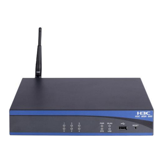
Item MSR 900/900W MSR 920/920W Rated voltage Rated voltage range: 100 VAC to range: 100 VAC to AC input voltage 240 VAC, 50 Hz or 240 VAC, 50 Hz or 60 Hz 60 Hz DC input voltage 12 V 12 V Max power 12 W 12 W... - Page 11 Figure 1-2 Front panel of the MSR 920/MSR 920W Table 1-2 Description of the LEDs, USB interface, and RESET button Item Status Description No power supply is present. Power supply LED The power supply operates (PWR) normally. Slow blinking The system operates normally. WLAN LED The system is working in situations Fast blinking...
-
Page 12: Rear Panel
Item Status Description A link is present. Ethernet interface Data is being transmitted or Blinking LEDs (0 to received. No link is present. — Connecting to a USB device interface Pressing the RESET button for over RESET — three seconds to restore the factory button default settings Generally, the WLAN LED on a wired MSR device (MSR 900 and... - Page 13 Figure 1-4 Rear panel of the MSR 920/MSR 920W Table 1-3 Description of the interfaces and antennas Item Description Console port Connecting to a PC through a console (CONSOLE) cable for system configuration Fixed Ethernet Uplink Layer 3 Ethernet interfaces for interfaces (ETH 0 and WAN connections ETH 1)
-
Page 14: Cable Connection
Cable Connection Follow these steps to connect cables for the MSR 900: Step1 Use a network cable to connect the uplink Ethernet interface (ETH 0 or ETH 1) to a WLAN access point. Step2 Use network cables to connect the downlink Ethernet interfaces to the Ethernet interfaces on user terminals. -
Page 15: Service Configuration
Service Configuration This configuration example uses a user terminal running Windows XP and Internet Explorer 6.0. Logging In to the Web Interface Follow these steps to log in to the Web interface for the first time: Step1 Type the default IP address http://192.168.1.1 in the address bar and press Enter to enter the page shown in Figure 3-1. -
Page 16: Network Access
Figure 3-2 Web configuration page Network Access Configuring Internet Access Through the Wizard The wizard allows you to set the parameters for Internet access quickly as following the system prompts. Step1 Select Wizard > Basic Configuration Wizard from the navigation tree in the configuration page to enter the welcome page shown in Figure 3-3. - Page 17 Step2 Click Next>> to enter the page displaying LAN interface parameters, as shown in Figure 3-4. Figure 3-4 LAN interface configuration page By default, all Ethernet interfaces belong to VLAN 1. Therefore, you need to specify the IP address and mask of the device as the IP address and subnet mask of VLAN 1.
- Page 18 Type the IP address of the device in the Gateway IP Address field to specify the device as a gateway. The gateway is responsible for data forwarding when DHCP clients access servers or hosts outside the current network segment. With the gateway address specified for the address pool, the device acts as the DHCP server and sends the gateway address together with the IP addresses to the clients.
-
Page 19: Configuring Broadband Internet Access Manually
Step4 Click Next>> after the configurations to enter the page displaying the configuration information, as shown in Figure 3-6. Figure 3-6 Basic configuration confirmation page Step5 Click Finish if the configuration information is correct. The system thus saves the configurations automatically. Click Close on the page shown below to finish the operation. - Page 20 Step1 Select Interface Setup > LAN Interface Setup from the navigation tree and select the VLAN Interface Setup tab to enter the page shown in Figure 3-8. Figure 3-8 VLAN interface configuration page By default, all Ethernet interfaces belong to VLAN 1. Therefore, you need to specify the IP address and mask of the device as the IP address and subnet mask of VLAN 1.
- Page 21 Type the IP address of the device in the Gateway field to specify the device as a gateway. The gateway is responsible for data forwarding when DHCP clients access servers or hosts outside the current network segment. With the gateway address specified for the address pool, the device acts as the DHCP server and sends the gateway address together with the IP addresses to the clients.
-
Page 22: Creating Wlan Connections
Figure 3-10 Configure PPPoE parameters Step4 Type the username and password for network access and click Confirm. Creating WLAN Connections Follow these steps to establish a wireless connection if a host is willing to access the network through WLAN and it supports 802.1b/g: Step1 Select Interface Setup >... - Page 23 Step2 Type the wireless service name, set the service type to crypto, and click Apply to bring the configuration into effect Figure 3-12 Wireless connection configuration page Step3 Configure a password for accessing the created WLAN (SSID). After creating a WLAN service, you can enter the page shown in Figure 3-13.
- Page 24 Step4 Click the plus sign “+” before Security Setup, set Authentication Type to OpenSystem, select the checkbox before Encryption, set WEP to WEP40, specify Key ID and Key Length, and enter the key in the WEP Key field. You can configure multiple SSIDs and assign different key IDs for them in case WEP encryption mode is selected.
- Page 25 Figure 3-15 Enter network and Internet connection page Figure 3-16 Network connection displaying page Step7 Double-click the Wireless icon to enter the WLAN connection configuration page. Then click Refresh network list in the navigation bar to search for available WLAN networks. A page displaying the current WLAN networks may appear as shown in Figure 3-17.
- Page 26 Figure 3-17 WLAN connection configuration page Step8 Click Change advanced settings in the left navigation bar to enter the page shown below. 3-12...
- Page 27 Figure 3-18 Enter advanced configuration page Step9 Click the Wireless Networks tab to enter the page shown in Figure 3-19, select the self-defined SSID displayed in the Preferred networks field, and then click Properties. 3-13...
- Page 28 Figure 3-19 WLAN connection configuration page Step10 Specify the Key index value as the key ID configured on the device and click OK. 3-14...
- Page 29 Figure 3-20 Configure the key index Step11 After returning to the page shown in Figure 3-18, select the WLAN connection configured on the router and click Connect to enter the page shown in Figure 3-21. Then type the key and click Connect. 3-15...
-
Page 30: Access Control
Figure 3-21 Enter the key for WLAN access Step12 Appearance of the page shown in Figure 3-22 indicates a successful WLAN connection, that is, you can access the Internet via the WLAN connection. Figure 3-22 Successful WLAN connection Access Control The access control function allows you to control the user access to the Internet. - Page 31 You can configure access control rules to define the time period, user IP addresses, port range, and data packet types. The MSR 900 supports configuring up to five access control rules, in the order the rules are configured. Select Security Setup > Access from the navigation tree to enter the page shown in Figure 3-23.
-
Page 32: Content Filtering
Item Description Specifies the ports through which hosts on the LAN Destination access the Internet. Port For example, for the telnet port (23), enter 23 ~ 23. Specifies the status of the rule: Deny: Filters out packets matching the rule while allowing other packets to pass. - Page 33 Figure 3-24 URL filtering configuration page In this configuration page, you can configure the filtering rules as needed and click Filter to finish the configuration process. Then the filtering rules are displayed in the Select the filtering condition value(s) field and these rules take effect instantly. Table 3-3 describes the URL filtering configuration items.
-
Page 34: Modifying User Password
Table 3-4 Description of the configuration effect URL address Keyword Description Filters out all pages of the www.abc.com — specified website Filters out the /index.html www.abc.com /index.html page of the specified website Filters out the /index.html and www.abc.com /index.html? /index.htm pages of the specified website Filters out all pages of the (news|tech)\.ab... - Page 35 Figure 3-25 User management configuration page Select the username from the user list, select the checkbox before Password Modify, type the new password and confirm it, and click Apply to finish the operation. 3-21...
-
Page 36: System Management
System Management Saving the Configuration Select System Management > Configuration from the navigation tree to enter the Save tab page, which is displayed by default, as shown in Figure 4-1. Figure 4-1 Save the configuration Click Save Current Settings to save the current configurations to the configuration file. -
Page 37: Configuration File Backup
Figure 4-2 Initialization Click Restore Factory-Default Settings to restore the initial settings. Configuration File Backup The configuration file backup module delivers the following functions: View the configuration file for the next boot, including .cfg and .xml files. Back up the configuration file for the next boot to the local user host. -
Page 38: Configuration Restoration
Configuration Restoration The configuration restoration function allows you to upload the configuration file with the extension of .cfg to the device in use for the next system boot. Select System Management > Configuration from the navigation tree and click the Restore tab to enter the page shown in Figure 4-4. Figure 4-4 Restore the configuration file Click Browse…... - Page 39 Select System Management > Configuration from the navigation tree and click the Backup and Restore tab to enter the page shown in Figure 4-5. Figure 4-5 Quick backup and restoration through the USB interface In the Device File(s) area, select the files to be backed up, and click the Backup button to backup the selected files to the destination device through the USB interface.
-
Page 40: Reboot
At a time, you can restore multiple files, but only one application file or configuration file can be included for restoration. Use the USB devices provided by H3C only for backing up and restoring configuration files. Reboot Before rebooting the device, save the configurations; otherwise, any configuration changes that have not been saved will get lost after the system reboots. -
Page 41: Snmp
You can choose to check whether the current configuration has been saved to the configuration file to be used at the next startup. If you select the checkbox before “Check whether the current configuration is saved in the next startup configuration file”, the system will check the configuration before rebooting the device. - Page 42 Figure 4-7 SNMP v1 and SNMP v2 configuration page Select the radio button before Enable to enable SNMP. Select the radio button before SNMPv1&v2 to specify the SNMP version. Configure Read Password and Read & Write Password, which are used when the NMS performs read or read-write operations on the device.
-
Page 43: Configuring Snmp V3
Configuring SNMP v3 Select System Management > SNMP from the navigation tree to enter the page shown in Figure 4-8. Figure 4-8 SNMP v3 configuration page Select the radio button before Enable to enable SNMP. Select the radio button before SNMPv3 to specify the SNMP version. - Page 44 Configure the security username, authentication password, and encryption password Security Username, Authentication Password, and Privacy Password fields respectively. SNMP v3 supports MD5 authentication and DES56 encryption.
-
Page 45: Troubleshooting
Troubleshooting The power LED (PWR) is off Observe the following points: A proper power adapter is used. The power cord is correctly connected. The power switch is turned on. The Ethernet interface LED (ETH) is off Observe the following points: The network cable is correctly connected. - Page 46 Suffers weak or unstable radio signals Observe the following points: Strong magnetic fields nearby or radio wave interference can be a problem. Keep the MSR 900 series routers and the user terminals away from strong magnetic fields and electrical devices with strong electric fields.
Need help?
Do you have a question about the MSR 900 Series and is the answer not in the manual?
Questions and answers