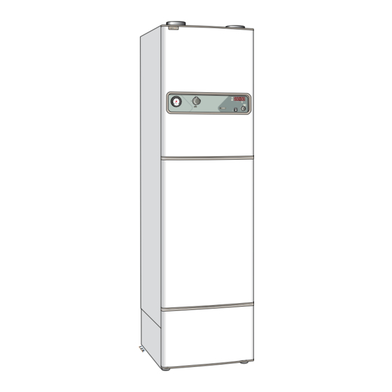
Nibe FIGHTER 310P Service Instructions Manual
Compressor heater
Hide thumbs
Also See for FIGHTER 310P:
Table of Contents
Advertisement
Available languages
Available languages
Quick Links
SIT SE/GB/DE 0220-1
KV-FIGHTER 200P/310P/315P
Kompressorvärmaren förhindrar att en större mängd
köldmedium samlas i kompressorn under dess stille-
ståndstid.
Montera vevhusvärmaren (68) eller (69) runt kompres-
sorn enligt vidstående bild efter att ha avlägsnat fläk-
ten. Värmaren får inte vidröra något kylrör.
Drag värmarens kabel genom en av genomföring-
arna på den horisontella plåten till höger om fläkt-
en.
Drag värmarens kabel genom dragavlastaren på
elkopplingsplåten.
FIGHTER 310P och 315P:
Borra ett hål (Ø 3,2 mm) till vänster om
ovanstående dragavlastare och nita fast
medföljande jordförgreningsstift och låsbricka om
detta stift inte redan är monterat.
Anslut kabeländarna (vid behov använd medföl-
jande kabelsats) i elkopplingsutrymmet enligt föl-
jande, se också elschema sidorna 4, 5, 6:
• Gul/grön kabel till jordförgreningsstift till vänster
om dragavlastaren.
• Blå kabel till position A2 på kontaktorn (10).
Vid behov använd medföljande förgrening.
• Brun kabel till position 5 på strömställaren (8).
Vid behov använd medföljande förgrening.
FIGHTER 200P:
Anslut kabeländarna (vid behov använd medföl-
jande kabelsats) i elkopplingsutrymmet enligt föl-
jande, se också elschema sida 7:
• Gul/grön kabel till jordförgreningsstift.
• Blå kabel till transformatorn (54), position 1.
• Brun kabel till transformatorn (54), position 15.
SERVICEINSTRUKTION / SERVICE INSTRUCTIONS / WARTUNGSANLEITUNG
R
Compressor heater / Kompressorheizer
611626
Montering
KV- FIGHTER 200P/310P/315P
Kompressorvärmare /
F 200P/ F310P/ F315P
LEK
Elinstallationen av detta tillbehör skall
utföras av behörig elinstallatör och
enligt gällande bestämmelser.
F200P
OBS!
68
69
Advertisement
Table of Contents

Summary of Contents for Nibe FIGHTER 310P
- Page 1 Drag värmarens kabel genom en av genomföring- arna på den horisontella plåten till höger om fläkt- Drag värmarens kabel genom dragavlastaren på elkopplingsplåten. FIGHTER 310P och 315P: F200P Borra ett hål (Ø 3,2 mm) till vänster om ovanstående dragavlastare och nita fast medföljande jordförgreningsstift och låsbricka om...
- Page 2 Pull the heater’s cable through the pull-relief clamp on the electrical connection plate. FIGHTER 310P and 315P: Drill a hole (Ø 3,2 mm) to the left of the above pull-relief clamp and rivet the accompanying earth branch pin and locking washer if not already mounted.
- Page 3 Durchführungen im vertikalen Blech rechts neben dem Ventilator ziehen. Das Kabel des Heizers durch die Zugentlastung auf der Schalttafel ziehen. FIGHTER 310P und 315P: Links neben besagter Zugentlastung ein Loch (Ø 3,2 mm) bohren und den mitgelieferten Erdabzweigungsstift mit Sicherungsscheibe festnieten, wenn der Stift nicht schon angebracht ist.
- Page 4 Elschema / Electric circuit diagram / Schaltplan F 310P 8,0 kW N N 3 – 230 V 12 V KV- FIGHTER 200P/310P/315P...
- Page 5 Elschema / Electric circuit diagram / Schaltplan F 315P/E 9,0 kW Re 9 Re 8 3,0 kW 6,0 kW 0 kW 1 2 3 4 5 6 1 2 3 4 5 6 ..MAX 1,25 A N L1 L2 L3 11.6 –...
- Page 6 Elschema / Electric circuit diagram / Schaltplan F 315P/G Re 9 Re 8 1 2 3 4 5 6 1 2 3 4 5 6 ..MAX 1,25 A N L1 L2 L3 11.6 – 12.2 12.6 – 29.9 – 230 V 12 V 9.N –...
- Page 7 Elschema F 200P AC/DC L1 N 230 V 12 V KV- FIGHTER 200P/310P/315P...
- Page 8 KV- FIGHTER 200P/310P/315P Box 14 Tel: 0433 - 73 000 NIBE AB Järnvägsgatan 40 Fax: 0433 - 73 190 SE-285 21 MARKARYD www.nibe.com...


Need help?
Do you have a question about the FIGHTER 310P and is the answer not in the manual?
Questions and answers