Table of Contents
Advertisement
Advertisement
Table of Contents

Related Manuals for Procom ECON-A-4C


Summary of Contents for Procom ECON-A-4C
- Page 1 OPERATING INSTRUCTIONS ECON-A-4C/A/S/M...
-
Page 3: Table Of Contents
INDEX Introduction Salient features, Protection & Supervision Display/ Front Panel Switches Description LED Annunciations Description Lamp Test Digital Input Analog Input Digital Output 10.0 Modes of Operation 10.1 AMF Mode (ECON-A & ECON -A-4C) 10.1.1 Auto Mode 10.1.2 Semi Auto Mode 10.1.3 Manual Mode 10.2 Auto Stop Mode ( ECON-A &... -
Page 4: Introduction
• ECON-M • ECON-A-4C: It is a AMF controller with 4 channel of analog measurement and can be site configured as ECON-A or ECON-S or ECON-M. • ECON-A: It is a AMF controller with 3 Analog channels and is site configurable to ECON-S or ECON-M... -
Page 5: Salient Features, Protection & Supervision
• 2.0 Salient Features, Protection and Supervision • Mains Measurements ◦ 1 Phase/ 3 Phase Voltage ◦ 1 Phase/ 3 Phase Current ◦ Frequency ◦ PF, KW, KVA, • Generator Measurements ◦ 1 Phase / 3 Phase Voltage ◦ 1 Phase / 3 Phase Current ◦... -
Page 6: Switches Description
◦ AMF Operation: 9 outputs (five fixed and three programmable) and one for charging Alternator • Fault Data Recording: Last 64 fault with date and time stamping • Event Recording: Last 64 event with date and time stamping • Start Stop Recording: Last 100 records with date and time stamping •... -
Page 7: Led Annunciations Description
Switch Switch Description Symbol Function Next Normal operation mode: In this mode, it is used to change the parameters being displayed on LCD. Programming Mode: Next key is used to select the next parameter to be programmed. Increment This key has dual function /Start Programming Mode: It is used to increment the value of the parameters under... -
Page 8: Lamp Test:
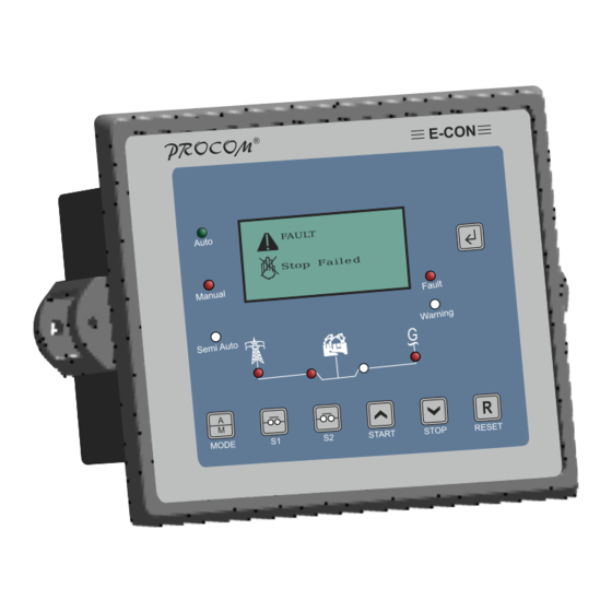
Nomenclature Symbol Description Semi Auto Led lights up when ECON is in Semi Auto Mains Voltage This symbol lights up continuously if Main is healthy else starts blinking. LED turns on in case the mains breaker is switched on or else turned off LED turns on in case the DG breaker is switched on or else turned off DG Voltage... -
Page 9: Analog Input
◦ Low Lube Oil Pressure Sensor ◦ High Water Temperature Sensor ◦ Low Fuel Level Sensor ◦ OIL Temperature (ECON-A-4C only ) • 9.0 Digital Output: ECON has 9 digital outputs : • Programmable output Three digital outputs can independently be configured for the any functions from the list below. -
Page 10: Auto Mode
Inputs: Emergency, V-Belt, RWL,, LLOP Switch etc) and internal faults (Measured Values faults: LLOP, HWT, Fuel, Over Load, voltage and frequency). On persistence of any fault for more than the programmed supervision delay,for that fault, generator is stopped, corresponding fault is announced & hooter is switched on. -
Page 11: Manual Controller ( All Models
• 10.2 MCCB Shunt trip or Auto Stop Mode (ECON-A , ECON -A-4C or ECON-S) This mode is a mix of Manual and Auto mode. In this mode the engine is manually started but its shut down on the restoration of the mains. To make sure that the engine is not shut down on load and also to recool the engine before shutting it down it has provision to activate the shunt trip coil of MMCB before shutting it down it has provision to activate the shunt trip coil of MMCB... - Page 12 To go to next menu press Start Switch the LCD shall display “Protection Parameter” To enter Protection Parameter setting mode press Next Switch. For any change in value, press Start switch and Stop switch. For next parameter, press Next Switch. To go to next menu press Start Switch the LCD shall display “Comm Rs485 Parameter”To enter Comm RS-485 Parameter setting mode press Next Switch.
-
Page 13: Parameter Mode
• 12.0 Parameter Mode: The following tables give the detailed descriptions. Please note that 20sec of inactivity will take the unit back in normal mode and all the changes done shall be cancelled. • 12.1 System Parameter Parameter Explanation of Parameter Factory Setting Range Name on... - Page 14 Fuel Sensor Select the installed sensor for Fuel Type A Type A, Sam-0, Sam-1, Electronics, Linear, 0-5V(0-100%), Disabled* Type A, Select the installed sensor for HWT Type A Type B,M&M, Sensor MNEPL,VE, TMTL AIR 1C, TMTL AIR 3C, TMTL WATER HUAFANG, TATA, GC(VDO),...
- Page 15 Contact ON These are three programmable None None Unit Healthy Load Pin 32,31,30 output which can be configured for Warning Fuel any one function from the list Pump Heater / Choke Pull Solenoid Over The Power(KW) above which the 1-9999 Load KW over load fault monitoring will start.
- Page 16 Digital Input This can be configured for one out the listed below Parameters. Oil Level Oil Level Temperature, Oil Temperature Canopy Canopy Temperature Temperature Digital Input This can be configured for one out Oil Temp. Oil Level the listed below Parameters. Oil Temp., Canopy door open Canopy Temp.
- Page 17 Digital input Normally open: Open contact is Normally Normally open 4 polarity healthy. open Normally close: Close contact is Normally healthy. closed Digital input Normally open: Open contact is Normally Normally open 5 polarity # healthy. open Normally close: Close contact is Normally healthy.
- Page 18 • 12.2 Generator Parameter Generator Max. Permissible Generator voltage, 270V 50-300V above this the Generator voltage is treated unhealthy & the Generator is stopped on voltage fault. Generator Min. permissible Generator voltage, 180V 50-300V below this the Generator voltage is treated unhealthy &...
- Page 19 Service Due Time, in hours, for next service due 250Hrs 10-999 Hrs warning. Crank Cut Auto disconnects the crank Voltage Voltage only Method command on detection of either Only Voltage or voltage buildup/ voltage or oil LLOP pressure build up Pick Up If the current level crosses this limit 1-9999...
-
Page 20: Amf Parameter
Engine On In manual mode, some time its Disable 00:01 to23.59 Time required to switch off/on the engine Disable* at a predetermined time. This setting Eü set the time for automatic switch ON of the engine 12.3 AMF Parameter Mains O/V Max. Permissible Mains voltage, 270V 50-300V above this the Mains voltage is... - Page 21 Phase This setting determines if the engine Disable Disable Sequence shall be started and load switch to 1-999 Sec Delay generator in case of reverse phase sequence of mains. Mains The time for which Mains should be 10 Sec 1-999 Sec Restoration continuously healthy before stopping Time...
- Page 22 Mains Over Econ-A can protect contactors from Disable Disable* Load mains over load. If this setting is 2-9999Amps enabled than the mains contactor shall drop after the mains current crosses the set limit for a programmed duration Mains O/L The monitoring duration for the 5 Sec 1-999 Sec Delay...
-
Page 23: Protection Parameter
Service In AMF mode,if this parameter is Disabled 2-999 Hrs Delay hour enabled, the engine will automatically start after this periodic time lapse from the last start. This is meant for periodic function Service Run The genset will work for this duration Disabled 1-999 Min min. - Page 24 LLOP Trip Monitoring value of lube oil pressure 0.4-8.5 Level below which LLOP trip is generated. Kg/cm Kg/cm LLOP Trip Monitoring time of lube oil pressure 10 Sec 0-999 Sec Delay after which LLOP trip is generated. HWT Trip Monitoring value of water 40-250 Level temperature below which HWT trip is...
- Page 25 Crank ON Maximum crank time 5 Sec 1-999 Sec Time Crank Gap The delay between two successive 5 Sec 1-999 Sec Time cranks Crank The maximum number of cranks that 1-10 Attempts shall be issued to start the Engine Solenoid The time for which stop solenoid will 22 Sec 1-999Sec...
-
Page 26: Reset Service Alarm
Note: To save the parameter, switch of and switch on the controller. • 13.0 Model Selection Chart Model Manual Auto Stop D5-D7 Oil Temp. Mode Mode Mode Input Sensor ECON-A-4C √ √ √ √ √ ECON-A √ √ √ ECON-S √... -
Page 27: Load Management
• 14.0 Load Management ECON-A has programmable contact Load management function. The load management contact will switch on when the current on the generator has crossed a programmed limit and will reset when the current has fallen below the reset programmed limit. This function can be used to cut-off unnecessary loads or start a second generator when the load goes above a limit. - Page 28 • 18.0 Terminal Numbers Terminal No. Description Fan Current S1 Fan Current S2 CT Common CT B CT Y CT R Sensor Oil Temp. Sensor LLOP Sensor HWT Sensor Fuel V-DG-N V-DG-B V-DG-Y V-DG-R V-Mains-N V-Mains-B V-Mains-Y V-Mains-R D Input 4 D Input 3 D Input 2 D Input 1...
- Page 29 Programmable Output 2 Programmable Output 1 Hooter Solenoid Crank Chg. Alt. Contact Battery(+ve)(8-35 V DC) Battery(-ve) Sensor(-ve) D Input 5 D Input 6 D Input 7 D(+): RS485 D(-):RS485 Page - 27 Operating Instructions...
- Page 30 Connect the wires as per the labelling done in back sticker: Page - 28 Operating Instructions...
-
Page 31: Specifications
• 19.0 Technical Specifications AC voltage withstand 330 VAC (Phase to neutral) Measurement Accuracy Voltages & Current 1% of Reading Power & Energies 2% of Reading Surge 1.2/50Usec 2.5KV Battery Voltage 9-35 V DC DC Interruption time 0.4 Sec Cut out Dimensions 155mm X 117mm Depth 41.8 mm... -
Page 32: Dimension
• 20.0 Dimensions...
Need help?
Do you have a question about the ECON-A-4C and is the answer not in the manual?
Questions and answers