Mitsubishi Electric FR-E700 Instruction Manual
Hide thumbs
Also See for FR-E700:
- Instruction manual (608 pages) ,
- Basic instruction manual (149 pages) ,
- Installation manuallines (38 pages)
Advertisement
INVERTER
FR-E700
INSTRUCTION MANUAL (BASIC)
FL remote communication function
FR-E720-0.1KNF to 15KNF
FR-E740-0.4KNF to 15KNF
Thank you for choosing this Mitsubishi Electric Inverter.
This Instruction Manual (Basic) provides handling information and precautions for use of the equipment.
Please forward this Instruction Manual (Basic) to the end user.
PRODUCT CHECKING AND PARTS IDENTIFICATION............... 1
1
INSTALLATION AND WIRING .................................................... 2
2
PRECAUTIONS FOR USE OF THE INVERTER.......................... 18
3
4
PARAMETER LIST.................................................................... 21
5
TROUBLESHOOTING ............................................................... 24
6
PRECAUTIONS FOR MAINTENANCE AND INSPECTION ......... 29
7
SPECIFICATIONS..................................................................... 31
8
To obtain the Instruction Manual (Applied) and the
Safety stop function instruction manual
Contact where you purchased the inverter, your Mitsubishi Electric sales
representative, or the nearest Mitsubishi Electric FA Center for the
following manuals:
Instruction Manual (Applied) [IB(NA)-0600398ENG]
Safety stop function instruction manual [BCN-A211508-004]
These manuals are required if you are going to utilize functions and
performance.
The PDF version of this manual is also available for download at
"MELFANS Web," the Mitsubishi Electric FA network service on the
world wide web (URL: http://www.MitsubishiElectric.co.jp/melfansweb)
CONTENTS
700
Advertisement

Related Manuals for Mitsubishi Electric FR-E700


Summary of Contents for Mitsubishi Electric FR-E700
-
Page 1: Table Of Contents
SPECIFICATIONS..............31 To obtain the Instruction Manual (Applied) and the Safety stop function instruction manual Contact where you purchased the inverter, your Mitsubishi Electric sales representative, or the nearest Mitsubishi Electric FA Center for the following manuals: Instruction Manual (Applied) [IB(NA)-0600398ENG] ... - Page 2 This Instruction Manual (Basic) provides handling information and precautions for use of the equipment. Please forward this Instruction Manual (Basic) to the end user. 2. Fire Prevention This section is specifically about safety matters CAUTION Do not attempt to install, operate, maintain or inspect the Inverter must be installed on a nonflammable wall without inverter until you have read through the Instruction holes (so that nobody touches the inverter heatsink on the...
- Page 3 (2) Wiring (5) Emergency stop CAUTION CAUTION Do not install a power factor correction capacitor or surge A safety backup such as an emergency brake must be suppressor/capacitor type filter on the inverter output provided to prevent hazardous condition to the machine side.
-
Page 4: Product Checking And Parts Identification
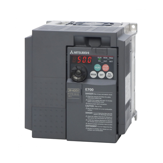
1 PRODUCT CHECKING AND PARTS IDENTIFICATION Unpack the inverter and check the capacity plate on the front cover and the rating plate on the inverter side face to ensure that the product agrees with your order and the inverter is intact. Inverter model FR - E720... -
Page 5: Installation And Wiring
Braking capability can be improved. (0.4K or higher) Always install a thermal relay when using a brake resistor whose capacity is 11K or higher. (Refer to page 13) Inverter (FR-E700-NF) EMC filter (ferrite core) * (FR-BSF01, FR-BLF) EMC filter (ferrite core) R/L1 S/L2 T/L3... - Page 6 Peripheral devices Peripheral devices Check the inverter model of the inverter you purchased. Appropriate peripheral devices must be selected according to the capacity. Refer to the following list and prepare appropriate peripheral devices: Moulded Case Circuit Breaker Magnetic Contactor (MC) (MCCB) ∗1 Motor Reactor...
- Page 7 Installation of the inverter and instructions Installation of the inverter and instructions (1) Installation of the inverter Enclosure surface mounting Remove the front cover and wiring cover to fix the inverter to the surface. (Remove the covers in the directions of the arrows.) FR-E720-0.1KNF to 0.75KNF FR-E720-1.5KNF or higher FR-E740-0.4KNF or higher...
- Page 8 Wiring Wiring 2.3.1 Terminal connection diagram Sink logic 1. DC reactor (FR-HEL) When connecting a DC reactor, remove the Main circuit terminal jumper across P1-P/+. Control circuit terminal *2 A brake transistor is not built-in to the 0.1K Brake unit and 0.2K.
- Page 9 Wiring 2.3.2 Terminal specifications Terminal Type Terminal Name Description Symbol R/L1, S/L2, AC power input Connect to the commercial power supply. T/L3 U, V, W Inverter output Connect a three-phase squirrel-cage motor. Connect a brake resistor (FR-ABR, MRS type, MYS type) across terminals P/+ P/+, PR Brake resistor connection and PR.
- Page 10 Wiring 2.3.3 Terminal arrangement of the main circuit terminal, power supply and the motor wiring Three-phase 200V class FR-E720-0.1KNF to 0.75KNF FR-E720-1.5KNF to 3.7KNF Jumper Jumper N/- P/+ R/L1 S/L2 T/L3 R/L1 S/L2 T/L3 Motor Power supply Power supply Motor FR-E720-5.5KNF, 7.5KNF FR-E720-11KNF, 15KNF R/L1 S/L2 T/L3...
- Page 11 Wiring 2.3.4 Cables and wiring length (1) Cable size and other specifications of the main circuit terminals and the earthing terminal Select the recommended cable size to ensure that a voltage drop will be 2% or less. If the wiring distance is long between the inverter and motor, a main circuit cable voltage drop will cause the motor torque to decrease especially at the output of a low frequency.
- Page 12 Wiring Total wiring length The overall wiring length for connection of a single motor or multiple motors should be within the value in the table below. 3.7K Pr. 72 PWM frequency selection Setting 0.1K 0.2K 0.4K 0.75K 1.5K 2.2K (carrier frequency) or Higher 200V class 200m...
- Page 13 Wiring 2.3.5 Wiring of control circuit (1) Terminal layout of control circuit terminal Recommended wire size: 0.3mm to 0.75mm +24 SD S1 S2 PC Y0 SE (2) Wiring method Wiring For the control circuit wiring, strip off the sheath of wires, and use them with a blade terminal. For a single wire, strip off the sheath of the wire and apply directly.
- Page 14 Wiring 3) Insert the wire into a socket. When using a single wire or a stranded wire without a blade terminal, push an open/close button all the way down with a flathead screwdriver, and insert the wire. Open/close button Flathead screwdriver NOTE When using a stranded wire without a blade terminal, twist enough to avoid short circuit with a nearby terminals or wires.
- Page 15 Wiring 2.3.6 Connecting the 24V external power supply FL remote communication between the master module and the inverter can be continued while the main power circuit is OFF if the 24V external power supply is connected across terminals +24 and SD. When the main circuit power supply is turned ON, the power supply changes from the 24V external power supply to the main circuit power supply.
- Page 16 Connection of a dedicated external brake resistor (MRS type, MYS type, FR-ABR) Connection of a dedicated external brake resistor (MRS type, MYS type, FR-ABR) Install a dedicated brake resistor (MRS type, MYS type, FR-ABR) outside when the motor driven by the inverter is made to run by the load, quick deceleration is required, etc.
- Page 17 FL remote communication specification FL remote communication specification Type Built-in to an inverter, RJ-45 connector connection method Power supply Supplied from the inverter or the 24VDC external power supply Connection cable FL-net dedicated cable (Refer to page 15) Maximum number of 64 units maximum connectable inverters Communication speed...
- Page 18 Wiring the FL-net dedicated cable Wiring the FL-net dedicated cable 2.7.1 Connecting to the network (1) Be sure to check the following points before connecting the inverter to the network. Check that the correct node address is set. (Refer to page 14) Check that the FL-net dedicated cable is correctly connected to the FL remote communication connector.
- Page 19 Wiring the FL-net dedicated cable 2.7.4 Connecting the FL-net dedicated cable Connect the FL-net dedicated cable to the FL remote communication connector. NOTE Do not connect the FL-net dedicated cable to the connector reserved for manufacturer settings. FL remote communication connector Connector reserved for manufacturer settings CAUTION Do not connect a parameter unit (FR-PU07, etc.) to the FL remote communication connector.
- Page 20 LED status LED status Each LED indicates the operating status of the inverter and network according to the indication status. TX RX : Communication set status LED : Device status LED TX/RX : Reception/transmission LED : Remote status LED 2.8.1 Device status LED (DEV), remote status LED (RMT) LED Status Node Status...
-
Page 21: Precautions For Use Of The Inverter
PRECAUTIONS FOR USE OF THE INVERTER 3 PRECAUTIONS FOR USE OF THE INVERTER The FR-E700 series is a highly reliable product, but incorrect peripheral circuit making or operation/handling method may shorten the product life or damage the product. Before starting operation, always recheck the following items. - Page 22 PRECAUTIONS FOR USE OF THE INVERTER (12) Across P/+ and PR terminals, connect only an external regenerative brake discharging resistor. Do not connect a mechanical brake. The brake resistor cannot be connected to the 0.1K or 0.2K. Leave terminals P/+ and PR open. Also, never short between these terminals.
-
Page 23: Failsafe Of The System Which Uses The Inverter
FAILSAFE OF THE SYSTEM WHICH USES THE INVERTER FAILSAFE OF THE SYSTEM WHICH USES THE INVERTER When a fault occurs, the inverter trips to output a fault signal. However, a fault output signal may not be output at an inverter fault occurrence when the detection circuit or output circuit fails, etc. -
Page 24: Parameter List
PARAMETER LIST 5 PARAMETER LIST For simple variable-speed operation of the inverter, the initial setting of the parameters may be used. Set the necessary parameters to meet the load and operational specifications. Parameter setting, change and check can be made from the operation panel. - Page 25 PARAMETER LIST Setting Initial Setting Initial Name Name Parameter Parameter Range Value Range Value Restart cushion time 0 to 60s Acceleration/deceleration time 0 to 400Hz, 9999 switching frequency 9999 Remote function selection 0, 1, 2, 3 Output current detection level 0 to 200% 150% Energy saving control...
- Page 26 PARAMETER LIST Setting Initial Setting Initial Name Name Parameter Parameter Range Value Range Value Parameter for manufacturer setting. Do not set. 400VDC/ Regeneration avoidance 300 to 800V 780VDC Stop-on contact control operation level 0, 1 ∗4 selection Regeneration avoidance Stop-on contact excitation 0 to 10Hz, 0 to 300%, compensation frequency limit...
-
Page 27: Troubleshooting
Reset method of protective function 6 TROUBLESHOOTING When a fault occurs in the inverter, the inverter trips and the display on the operation panel automatically changes to one of the following fault or alarm indications. If the fault does not correspond to any of the following faults or if you have any other problem, please contact your sales representative. - Page 28 List of fault or alarm indications List of fault or alarm indications When a fault occurs, the inverter trips and the PU display automatically changes to one of the following fault or alarm indications. Function Name Description Corrective action Display Appears when operation was tried during Operation panel lock Press...
- Page 29 List of fault or alarm indications Function Name Description Corrective action Display Keep load stable. Check the wiring to make sure that output short circuit/ Appears when an overcurrent occurred during Overcurrent trip during ground fault does not occur. constant speed constant speed operation.
- Page 30 List of fault or alarm indications Function Name Description Corrective action Display Refer to "Troubleshooting in FL remote communication" in the Instruction Manual (Applied), and take the corrective Stops the inverter output at a communication line action for the error. Communication option fault error of FL remote communication.
- Page 31 Check first when you have a trouble Check first when you have a trouble If the following malfunctions occur, refer to the troubleshooting in the Instruction Manual (Applied). Motor does not start Motor or machine is making abnormal acoustic noise Inverter generates abnormal noise Motor generates heat abnormally Motor rotates in the opposite direction...
-
Page 32: Precautions For Maintenance And Inspection
Inspection items 7 PRECAUTIONS FOR MAINTENANCE AND INSPECTION The inverter is a static unit mainly consisting of semiconductor devices. Daily inspection must be performed to prevent any fault from occurring due to the adverse effects of the operating environment, such as temperature, humidity, dust, dirt and vibration, changes in the parts with time, service life, and other factors. - Page 33 Replacement of parts When using the safety stop function, periodic inspection is required to confirm that safety function of the safety system operates correctly. For more details, refer to the Safety stop function instruction manual (BCN-A211508-004). (Please contact your sales representative for the manual.) Replacement of parts The inverter consists of many electronic parts such as semiconductor devices.
-
Page 34: Specifications
Although the FR-E700 series has the built-in inrush current limit circuit, select the DC power supply considering the inrush current at powering ON as the inrush current four times of the rated inverter flows at powering ON. - Page 35 Common specifications Common specifications Soft-PWM control/high carrier frequency PWM control (V/F control, Advanced magnetic flux vector control, Control method General-purpose magnetic flux vector control, Optimum excitation control are available) Output frequency range 0.2 to 400Hz Frequency setting resolution 0.01Hz (digital input) Frequency accuracy Within 0.01% of the set output frequency (digital input)
- Page 36 Outline dimension drawings Outline dimension drawings (Unit:mm) • Three-phase 200V class Inverter model FR-E720-0.1KNF 89.5 FR-E720-0.2KNF 121.5 FR-E720-0.4KNF 141.5 FR-E720-0.75KNF FR-E720-1.5KNF 144.5 FR-E720-2.2KNF 151.5 FR-E720-3.7KNF FR-E720-5.5KNF FR-E720-7.5KNF FR-E720-11KNF FR-E720-15KNF • Three-phase 400V class Inverter model FR-E740-0.4KNF FR-E740-0.75KNF FR-E740-1.5KNF FR-E740-2.2KNF FR-E740-3.7KNF FR-E740-5.5KNF FR-E740-7.5KNF FR-E740-11KNF...
- Page 37 CE marking. The authorized representative in the EU The authorized representative in the EU is shown below. Name: Mitsubishi Electric Europe B.V. Address: Gothaer Strasse 8, 40880 Ratingen, Germany Note We declare that this inverter, when equipped with the dedicated EMC filter, conforms with the EMC Directive in industrial environments and affix the CE marking on the inverter.
- Page 38 Low Voltage Directive We have self-confirmed our inverters as products compliant to the Low Voltage Directive (Conforming standard EN 61800- 5-1) and place the CE mark on the inverters. Outline of instructions ∗ Do not use an earth leakage circuit breaker as an electric shock protector without connecting the equipment to the earth. Connect the equipment to the earth securely.
- Page 39 ∗ Select a UL and cUL certified fuse with Class T fuse equivalent cut-off speed or faster with the appropriate rating for branch circuit protection, or a UL489 molded case circuit breaker (MCCB) in accordance with the table below. FR-E720- 0.75 Rated fuse voltage(V) 240V or more...
- Page 40 Appendix 2 Instructions for UL and cUL (Standard to comply with: UL 508C, CSA C22.2 No. 14) 1. General Precaution The bus capacitor discharge time is 10 minutes. Before starting wiring or inspection, switch power off, wait for more than 10 minutes, and check for residual voltage between terminal P/+ and N/- with a meter etc.
- Page 41 REVISIONS *The manual number is given on the bottom left of the back cover. Print Date Revision Manual Number Feb. 2010 IB-0600397ENG-A First edition Jan. 2011 IB-0600397ENG-B Modification Safety stop function For Maximum Safety • Mitsubishi inverters are not designed or manufactured to be used in equipment or systems in situations that can affect or endanger human life.
- Page 42 Additional notes for Instructions for UL and cUL Motor overload protection When using the electronic thermal relay function as motor overload protection, set the rated motor current in Pr.9 Electronic thermal O/L relay CAUTION Motor over temperature sensing is not provided by the drive. General precaution CAUTION - Risk of Electric Shock - The bus capacitor discharge time is 10 minutes.
- Page 43 Year, and the Month is indicated by 1 to 9, X (October), Y (November), or Z (December). •Authorized sales representative (importer) in the CU area The authorized sales representative (importer) in the CU area is shown below. Name: Mitsubishi Electric (Russia) LLC Address: 52, bld 1 Kosmodamianskaya Nab 115054, Moscow, Russia Phone: +7 (495) 721-2070...
- Page 44 電器電子製品有害物質使用制限について 中華人民共和国の『電器電子製品有害物質使用制限管理弁法』に基づき、 「電器電子製 品有害物質使用制限の標識」の内容を以下に記載いたします。 Restricted Use of Hazardous Substances in Electronic and Electrical Products The mark of restricted use of hazardous substances in electronic and electrical products is applied to the product as follows based on the “Management Methods for the Restriction of the Use of Hazardous Substances in Electrical and Electronic Products”...
- Page 45 インバータが装備している短絡保護は、分岐回路を保護するものではありません。 また、分岐回路保護用のクラスT、クラスJ、クラスCCタイプのヒューズ以上の遮断速度を持つ適 36ページ 切な定格のUL、cUL認定ヒューズ、もしくはUL489配線用遮断器(MCCB)を に従い選 定し、使用してください。 FR-E700 Series Instruction Manual Supplement Instructions for UL and cUL have been revised. Instructions for UL and cUL (Standard to comply with: UL 508C, CSA C22.2 No. 14) Installation The below types of inverter have been approved as products for use in enclosure and approval tests were conducted under the following conditions.
- Page 46 Model Manufacturer Rated Voltage, Vac MMP-T32 Mitsubishi Electric Corp. 480Y/277 Suitable for Use in a Circuit Capable of Delivering Not More Than 50 or 25 kA rms Symmetrical Amperes, 480Y/277 Volts Maximum when protected by the Type E Combination motor Controllers indicated in the above table.
- Page 47 Korean FA Center India FA Center MITSUBISHI ELECTRIC AUTOMATION KOREA CO., LTD. B1F,2F, 1480-6, Gayang-Dong, Gangseo-Gu, Seoul, 157-200, Mitsubishi Electric Asia Pvt. Ltd. Gurgaon Branch Korea 2nd Floor, DLF Building No.9B, DLF Cyber City Phase TEL. +82-2-3660-9607 FAX. +82-2-3664-0475 Gurgaon 122002, Haryana, India TEL.
- Page 48 HEAD OFFICE: TOKYO BUILDING 2-7-3, MARUNOUCHI, CHIYODA-KU, TOKYO 100-8310, JAPAN IB-0600397ENG-B(1101)MEE Printed in Japan Specifications subject to change without notice.