Table of Contents
Troubleshooting

Related Manuals for DeVilbiss IntelliPAP DV54


Summary of Contents for DeVilbiss IntelliPAP DV54
- Page 1 ® ™ D e V ilb is s In t e lliP A P P A P D e v ic e Service Manu al ® ™ D e V ilb is s S le e p Cu b e P A P D e v ic e Model D V54 CA UTION–...
- Page 2 LT-2027...
-
Page 3: Table Of Contents
G. Blower R emoval ..........E. Setting Pressures and Features ......H. Blower R eplacement ........... F. Images: DeVilbiss DV54 PAP ......... I. K eyPad & LCD Display R emoval and R eplacement ..2. Description of Normal Operation .... -
Page 4: General Information
Information to which you should pay device. The connector must only be used with acces- special attention. sories approved for use by DeVilbiss. Do not attempt to attach any other device to this connector as it may PLEASE READ ALL INSTRUCTIONS damage the CPAP or the accessory device. -
Page 5: Travel
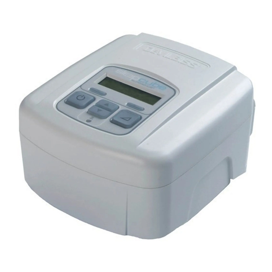
C. TRAVEL F. IMAGES: DEVILBISS DV54 PAP The DeVilbiss DV54 PAP Figures A and B: DV54 Device Back and Bottom Views • Automatically adjusts for altitudes between sea level 1. Air supply port and 9000 ft (2750 m) on back of •... -
Page 6: Description Of Normal Operation
D escrip tion of N ormal O p eration An AC line cord (100-240 VAC, 50/60 Hz) or a DC line cord (12 VDC) supplies electrical power to the DV54 PAP . The PAP converts the AC input voltage to DC voltage by means of an internal switch mode power supply and uses the DC voltage to power the internal electronics of the unit, such as microcontroller, motor control circuitry, blower, LCD display, etc. -
Page 7: Cleaning And Disinfecting
CAUTION– Always work in an ESD (electro static discharge) safe environment when as- sembling or disassembling electronic components. NOTE– DeVilbiss does not require disinfection as part of unit maintenance. If disinfection is desired, the following procedure is recommended. NOTE– Parts needed to perform the disinfection procedure are NOT covered under the DV54 PAP warranty as listed in this manual. - Page 8 Disinfection Procedure for the DV Series PAP 1. Make certain that the device is not connected to a power source. 2. Dispose of the mask, headgear, air supply tubing, gray air inlet fi lter and white fi ne particle fi lter, if applicable. 3.
- Page 9 11. Remove the grommet that seals the blower’s wire harness. (Fig. 7) 12. Remove the heater wire harness connector from the bottom of the chassis by sliding the connector outward while pulling the top retaining tab upward slightly. (Fig. 8) 13.
-
Page 10: Maintenance
Clean mask and headgear per manufacturer’s instructions. C. REQ UIRED 2-YEAR MAINTENANCE— EQ UIPMENT PROVIDER DeVilbiss requires the following maintenance from the equipment provider: Test pressure accuracy using procedures listed under Pressure Accuracy Test. If the device is out of calibration, follow corrective procedures as listed. -
Page 11: Testing
Testing The following test procedures verify correct operation of the B. FLOW ACCURACY TEST DV54 PAP and should be performed on all repaired units. Additional equipment required: PAP to PC cable (DV51D- NOTE– Verify that the DV54 PAP contains the latest fi rm- 615), a calibrated volumetric mass fl... -
Page 12: Keypad Test
C. KEYPAD TEST shows ‘Mask OFF’. If the mask alert did not appear, go to step 14. No additional equipment required. 12. After another 20 seconds the blower should turn 1. Apply AC power to the unit. If the blower is running, OFF via the Auto-OFF feature. -
Page 13: Alerts And Device Faults
A lerts and Device Fau lts A. ALERTS VISIBLE TO PATIENTS C. READING AND CLEARING THE LAST DEVICE FAULT CODE Alert Description NOTE– The last device fault code is stored in EEPROM to Delay running Comfort Delay is active assist in fi eld service of the unit. XX minutes left Mask leak = XX%. -
Page 14: Calibration
PAP sends ‘ Cal press offset ’ when spin- ning is stopped. DeVilbiss recommends calibrating the DV54 PAP if replacing the PC During this stage of the procedure the PAP stops control board or when testing or troubleshooting indicate calibration the blower and saves the pressure sensor and is required. -
Page 15: Calibration Errors
B. CALIBRATION ERRORS Code Description Calibrate Motor Stop Error. The blower did not stop during device calibration. This error only oc- curs during the calibration procedure. Calibrate Flow Balance Error. The fl ow balance digital potentiometer did not adjust during device calibration. -
Page 16: Troubleshooting
Troublesh ooting Symptom Action (for symptoms listed at left, follow the steps listed below) Blower does 1. Remove the cover. See Service Instructions. not start when 2. Search for disconnected wire harnesses and reconnect, if powered up needed. E03, E04, or 3. - Page 17 Symptom Action (for symptoms listed at left, follow the steps listed below) Pressure or 1. Remove the cover. See Service Instructions. fl ow out of 2. Search for disconnected, occluded, or kinked tubing on the pres- tolerance sure sensor or chassis. Correct any issues. (Pressure ±...
-
Page 18: Service Instructions
S ervice Instructions NOTE– After performing any service on the DV54 PAP , please test the unit to ensure proper operation and calibrate, if necessary. A. COVER REMOVAL CAUTION– Failure to wear anti-static equipment during service may damage this device. 1. -
Page 19: Control Pc Board Replacement
D. CONTROL PC BOARD REPLACEMENT CAUTION– Failure to wear anti-static equipment during service may damage this device. 1. See instructions above to remove the cover and the control PC board. 2. Wearing an anti-static device, verify that the silicone rattails holding the key- board onto the control board are pulled through the appropriate holes in the board. -
Page 20: Power Supply Board Removal
18. Read the Compliance Meter (“ Up<cr> ”)– a new PC board should have 00000 hours. Clear the Compliance meter if it is not zero by typing ‘ Up=c<cr> ’. The CPAP will return 000000.0 hours. 19. Check the fi rmware and hardware version information. Read and record the following: •... -
Page 21: Blower Removal
G. BLOWER REMOVAL CAUTION– Failure to wear anti-static equipment during service may damage this device. 1. See instructions above to remove the cover and control PC board 2. Carefully remove the silicone grommet holding the blower wire harness. (Fig. 4) 3. -
Page 22: Keypad & Lcd Display Removal And Replacement
I. KEYPAD & LCD DISPLAY REMOVAL AND REPLACEMENT CAUTION– Failure to wear anti-static equipment during service may damage this device. 1. See instructions above to remove cover and control PC board. 2. Wearing an anti-static device, disconnect the two LCD display wire harnesses. (Fig. -
Page 23: Unit Specifi Cations
10. U nit Specific ations Unit Specifi cations Size 4.2” H x 6.5” W x 6.9” D (10.7 cm x 16.5 cm x 17.5 cm) Weight 2.7 lbs. (1.22 kg) Electrical Requirements 100-240V~, 50/60 Hz DC Operation 12 Volt, 5 Amps Maximum Power Consumption 65 watts max from AC power source (PAP device only) AutoAdjust CPAP Pressure Range... -
Page 24: General Information- Dv5Hh
WARNING: Important safety information for hazards B. TRAVEL that might cause serious injury. The DeVilbiss DV5HH humidifi er system CAUTION: Information for preventing damage to the product. • Automatically accepts line voltages of 100-240 V , 50/60 Hz... -
Page 25: Description Of Normal Operation Dv5Hh
12. Description of Normal Operation DV5HH The heated humidifi er connects mechanically and electrically to a DV5X series PAP be- tween the air stream going from the PAP to the patient. The keypad on the PAP controls the heated humidifi er’s output and ON/OFF functions. Before operation, the humidifi er chamber is fi... -
Page 26: Maintenance And Testing Dv5Hh
13. Maintenance and Testing DV5HH A. CLEANING AND DISINFECTION See the DV5HH Instruction Guide (A-DV5HH) for information on cleaning the humidifi er chamber and heater base. The DV5HH Standard Heated Humidifi er is single patient use only and therefore does not require disinfection. -
Page 27: Troubleshooting- Dv5Hh
14. Troubleshooting DV5HH HEATER Symptom Action The PAP does not recognize the Connect the heater to a known good PAP device, if one is available. If PAP display still does heater. (With the PAP blower ON, not recognize the heater, replace the heater. the PAP display does not indicate If a known good PAP device is not available, remove the PAP from the heater and check the Heat:xxx on the bottom line.) -
Page 28: Service Instructions Dv5Hh
15. Service Instructions DV5HH A. REMOVING THE DV5HH BASE COVER 1. Remove the humidifi er chamber from the DV5HH base. 2. Push the release button (Fig. 1) on the DV5HH base and lift the PAP device off the heater base and set aside in a safe place. 3. -
Page 29: Removing And Replacing Silicone Manifold
C. REMOVING AND REPLACING SILICONE MANIFOLD 1. Remove the cover as described above. 2. Squeeze the inlet port on the silicone manifold and push the port down into the hole in the top cover, gently releasing the manifold from all other connections. Discard the manifold or set aside in a safe place, if returning to the unit. -
Page 30: Unit Specifi Cations- Dv5Hh
16. Unit Specific ations DV5HH Humidity Output ≥ 10 mgH2O/L air (in the operating fl ow range) Chamber/Cradle Dimensions Size 2.6” H x 6.3” W x 8.4” D (6.6 cm x16.0 cm x 21.3cm) Weight 1.75 lbs. (0.794 Kg) Electrical Rating: Electrical Supply Frequency 50/60 Hz Power Consumption... -
Page 31: Ordering And R Eturning Parts
17. Ordering and R eturning P arts DV54 AND DV5HH A. ORDERING NON-WARRANTY REPLACEMENT PARTS Order non-warranty parts and literature from your distributor or, if you have a DeVilbiss account, from DeVilbiss Customer Service. To expedite the process, be prepared to provide the following information: Account and ship-to numbers •... -
Page 32: Parts List
18. Parts List DV54 PAP DV5HH Air-Inlet Filter (4/pk) DV51D-602 Heated humidifi er assembly DV5HH Optional Fine Particle Filter (4/pk) DV51D-603 Humidifi er chamber DV5C Air supply tubing 7351D-616 Sealing gasket for chamber DV5C-614 Air supply support plug DV51D-604 Silicone manifold for heater DV5H-600 Disinfection kit DV51D-682... -
Page 33: W Arranties
Any defective part(s) will be repaired or re- if the device has not been tampered with or used improperly placed at DeVilbiss’s option if the unit has not been tampered during that period. Make certain that any malfunction is not with or used improperly during that period. - Page 36 FRANCE GERMANY 33-274-55 44-00 49-7253-980-460 DeVilbiss Healthcare is a division ©2008 DeVilbiss Healthcare 08.08 of Sunrise Medical HHG, Inc. LT-2027 Rev. A D e V i l b i s s H e a l t h c a r e , • 1 0 0 D e V i l b i s s D r i v e • S o m e r s e t , PA 1 5 5 0 1 U S A 8 0 0 - 3 3 8 - 1 9 8 8 •...
Need help?
Do you have a question about the IntelliPAP DV54 and is the answer not in the manual?
Questions and answers