
Summary of Contents for RindaTechnologies TechMate Pro
- Page 1 TechMate Pro Marine Scan Tool The fastest and easiest way to troubleshoot Marine Electronic Fuel Injection Systems. User’s Guide Rinda Technologies, Inc. www.rinda.com...
- Page 3 TechMate Pro Marine Scan Tool USER’S GUIDE Revision 2 Rinda Technologies, Inc. 4563 N. Elston Ave. • Chicago, IL 60630 www.rinda.com Tel: (773) 736-6633 Fax: (773) -736-2950 Copyright © 2015 Rinda Technologies, Inc.
- Page 4 Limited Warranty To the original purchaser only, Rinda Technologies, Inc. warrants the supplied scan tool hardware to be free from defects in materials and workmanship under normal use for a period of 1 year from date of purchase as evidenced by a copy of the sales receipt.
-
Page 5: Table Of Contents
Table of Contents Safety Precautions ............6 Overview ................7 Scan Tool Key Functions ..........8 Menu Operation ..............9 Tool Setup ................10 Engine / EFI System Support ........... 11 GM Marine EFI (MEFI) ..........12 Volvo Penta EGC EFI ........... 21 Pleasurecraft / Crusader ECM-07 &... -
Page 6: Safety Precautions
Safety Precautions Before attempting to use the TechMate scan tool please read and observe the following safety precautions: • Always refer to and follow the engine and boat manufacturer’s safety and service procedures to prevent personal injury and equipment damage. •... -
Page 7: Overview
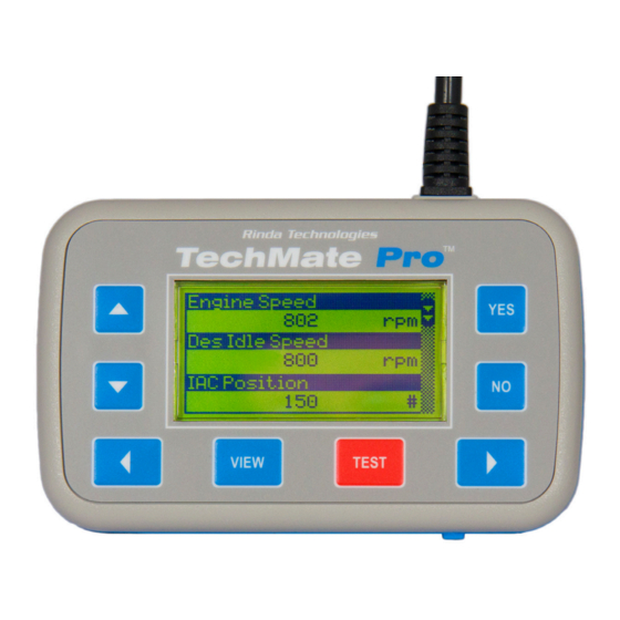
Overview What is the TechMate Pro Scan Tool? The TechMate Pro is a high performance diagnostic scanner that has been designed for marine service applications. The scanner supports a wide range of inboard, sterndrive and outboard electronic engine control systems. -
Page 8: Scan Tool Key Functions
Scan Tool Key Functions Key Functions Used to scroll through a menu, list or increase a value Used to scroll through a menu, list or decrease a value Used to choose / select menu items, confirm choices. Used to exit menus, cancel selections, decline choices. Navigates right. -
Page 9: Menu Operation
Menu Operation Menu Operation The ▲ and ▼ keys are used to access all menu choices throughout the operation of the scan tool. The scan tool’s main menu is shown below in Figure 2. The YES key is used to select or activate the currently highlighted menu item. MAIN MENU Sterndrives/Inboards Mercury Outboards... -
Page 10: Tool Setup
Used to adjust the current time and date stored in the tool’s internal real-time clock. The TechMate Pro maintains the current time and date via a built-in clock circuit which is power by a replaceable CR2032 coin cell battery. Battery life is approximately 5 to 7 years. -
Page 11: Engine / Efi System Support
Engine Support Engine / EFI System Support The TechMate Pro scan tool supports a wide variety of marine electronic engine control systems. At the time of this writing the following system types are sup- ported as summarized below. • All marine engines equipped with GM MEFI (MEFI-1 thru MEFI-6) Depending upon the model year these engines include MerCruiser, Volvo Penta, Indmar, Pleasurecraft, Crusader, Marine Power, Kodiak, Flagship Marine and others.) -
Page 12: Gm Marine Efi (Mefi)
GM Marine EFI Scan Tool GM EFI Compatibility At the date of publication of this manual the TechMate Pro scan tool is compatible with 1993 and newer GM Marine EFI systems being used by a variety of marine engine manufacturers. These manufacturers include Volvo... - Page 13 GM Marine EFI Connecting to GM MEFI-1 thru MEFI-4 systems (For connecting to GM MEFI-5 or MEFI-6 CAN based systems see page 15) 1) Locate the engine’s 10 pin marine diagnostic link connector (DLC). The loca- tion of this connector is specified in the engine manufacturer’s service manu- al.
- Page 14 GM Marine EFI 2) With the engine’s ignition switch in the OFF position, plug the scan tool’s communication cable into the diagnostic connector. Scan tool adapter #94005 is required for this application as shown below. GM Marine EFI Adapter Rinda Tech P/N 94005 3) Once the tool is connected, turn the ignition switch ON and start the engine if necessary.
- Page 15 GM Marine EFI Engine #1 / Engine #2 Selection (MEFI 1 - 4 ECMs Only) This menu allows you to select which engine you would like to service. For a single engine system choose Engine #1. For a twin engine system where the engines are electronically linked together choose Engine #1 or Engine #2.
- Page 16 GM Marine EFI Service Mode Function (MEFI-1 thru MEFI-4 ECMs Only) The Service Mode function is primarily used to set an engine’s base spark timing. This function applies to engines equipped with a standard distributor. It is not used on engines with Distributorless Ignition Systems (DIS) or those employing a HVS distributor (i.e.
- Page 17 GM Marine EFI Reset BLM Values (MEFI-5 and MEFI 6 only) This function applies to MEFI-5 and MEFI-6 based engines that are equipped with oxygen sensors. During engine operation the ECM learns and stores mod- ifications to it’s factory preset fuel delivery values. This allows the ECM to adapt itself to the unique operating conditions it is subjected to in a particular engine application.
- Page 18 GM Marine EFI MEFI 1 & 2 Output Tests MEFI-1 EFI Output Tests (MerCruiser only) ECM Pin # Buzzer Circuit Output 1 J2-11 Buzzer Circuit Output 2 J2-27 Fuel Pump Output J2-9 IAC Motor Reset MEFI-1 EFI Output Tests (Volvo & Other Makes) Over Temp Lamp J2-11 Buzzer Output...
- Page 19 GM Marine EFI MEFI 3 & 4 Output Tests MEFI-3 Output Tests ECM Pin # General Warning #1 Output J1-21 Buzzer Output J1-26 RPM Controlled Output J1-8 Oil Level Lamp J1-25 Check Gauges Lamp J1-7 Check Engine Lamp J1-9 General Warning #2 Output J1-22 Fuel Pump Output J1-23...
- Page 20 GM Marine EFI MEFI 5 & 6 Output Tests MEFI-5 Output Tests ECM Pin # MIL Lamp J1-12 Fuel Pump Output J1-13 Check Gauges Lamp J1-41 General Warning #1 Output J1-51 General Warning #2 Output J1-52 RPM Controlled Output J1-53 Warning Horn Output J1-54 Governor Status Lamp...
-
Page 21: Volvo Penta Egc Efi
Volvo Penta gasoline marine engines for the 2006 model year. Connecting to the Volvo Penta EGC System The TechMate Pro scan tool provides a comprehensive set of diagnostic and support functions for troubleshooting EGC equipped engines. Connection and operation of the tool is simple and straight forward. - Page 22 Volvo Penta EGC 3) Once the tool is connected turn the ignition switch ON and start the engine if necessary. If the engine will not start, leave the ignition switch ON and proceed. 4) After the scan tool displays its initial opening messages, use the ▲ and ▼ keys to select “Sterndrives / Inboards”...
- Page 23 Volvo Penta EGC ECM Info data list: Selecting this data list allows a technician to view version, serial number and cal- ibration information related to the engine and EGC module. This information in- cludes a variety of non-diagnostic data including hardware and software version numbers, calibration checksums, serial numbers and engine firing order data.
- Page 24 Volvo Penta EGC ECM Functions The ECM Functions option provides access to a variety of EGC functional tests. • IMPORTANT: Before performing any ECM or engine test refer to the engine manufacturer’s service literature for safety precautions and proper engine test procedures. To access the ECM Functions menu perform the following steps: 1) After selecting the “ECM Functions“...
- Page 25 Volvo Penta EGC Spark Fire Test This test allows individual spark outputs to be fired. • WARNING: Engine backfire and external flame can occur during this test. As a safety precaution purge fuel vapors from the engine before proceeding. Do not remove the flame arrestor if the engine is equipped with one.
- Page 26 Volvo Penta EGC Relay Test This test allows the EGC module’s relay outputs to be activated. The test must be performed with Key ON / Engine OFF. Upon selecting this test you will be prompted to select either the Ignition Relay output or All Relays (including the Fuel Pump relay).
- Page 27 Volvo Penta EGC Drive by Wire Test This test is available only when connected to engines equipped with Electronic Throttle Control (ETC). The test allows a technician to check the functionality of the ETC system by commanding the engine throttle blade to track helm throttle control lever movements.
-
Page 28: Pleasurecraft / Crusader Ecm-07 & Ecm-08
PCM / Crusader ECM-07 & ECM-08 Figure 9 PCM / Crusader GCP ECM Pleasurecraft Engine Group, manufacturer of both PCM and Crusader brand engines, introduced their ECM-07 engine control system on 2007 model year engines. Engines produced prior to the 2007 model year used GM-Delphi MEFI control modules which are described starting on page 12 of this manual. -
Page 29: Indmar Gcp Efi
CAN Network Adapter Rinda Tech P/N 94029 The TechMate Pro scan tool fully supports both the type 1 and type 2 modules with an extensive set of diagnostic functions. Both type 1 and type 2 modules require use of the #94029 scan tool CAN network adapter (shown above) for diagnostic communication. -
Page 30: Ilmor Mv8 Efi
Figure 11 above. This module was a direct replacement for the GM-Delphi MEFI-5 modules used on some early MV8 engines. The TechMate Pro scan tool offers an extensive set of diagnostic functions when connected to MV8 equipped engines.. Connecting the scan tool requires adapter #94029 (CAN Network Adapter) as shown in the photo at the bottom of this page. -
Page 31: Ilmor Mv10 Efi
Ilmor MV10 ECM Figure 12 Ilmor MV10 ECM The TechMate Pro scan tool supports 2009 and newer Ilmor MV10 engines equipped with Ilmor’s proprietary EFI system. The scan tool displays both live data and fault codes on this system. Note: MV10 engine models prior to 2009 (Gen III engines and earlier) use a Chrysler ECM and require an automotive OBD-II scanner for diagnosis. -
Page 32: Obd-M Compliant Efi
OBD-M Compliant ECMs The TechMate Pro scan tool supports marine engines that comply with the 2008 California / EPA mandated OBD-M diagnostic specification. The scan tool dis- plays both live data and fault codes on these systems. OBD-M live data The live data displayed by the scan tool is dependent upon the engine manufac- turer’s engine control system configuration. - Page 33 MerCruiser engines in October of 2000. Connecting to the PCM-555 EFI System The TechMate Pro scan tool provides an extensive set of diagnostic and support functions for troubleshooting engines equipped with the Mercury/MerCruiser PCM-555 engine control system. Connection and operation of the tool is simple and straight forward.
-
Page 34: Mercruiser Pcm-555 / Ecm-555 Efi
MerCruiser PCM-555 EFI 4) After the scan tool displays its initial opening messages use the ▲ and ▼ keys to highlight the ““Sterndrive / Inboards” option from the main menu then press the YES key to select it. Obtaining Data After selecting the “Sterndrive / Inboards”... - Page 35 MerCruiser PCM-555 EFI PCM History Selecting the “PCM History” menu choice displays a sub-menu of items associat- ed with the PCM’s fault history memory as shown in Figure 16. PCM HISTORY Freeze Frame Memory Fault Seconds Erase Fault History RPM History Erase RPM History Figure 16 PCM History Menu Freeze Frame Memory...
- Page 36 MerCruiser PCM-555 EFI Fault Seconds When critical faults occur and remain active the PCM-555 keeps track of how many seconds the fault has persisted during engine operation. The type and number of critical faults this function keeps track of is pre-selected by the engine manufacturer.
- Page 37 MerCruiser PCM-555 EFI PCM System Info The PCM-555 control module contains an area of memory that is used to store helpful text information for a service technician. This information consists of many lines of text which describe basic engine settings, capacities, etc, as well as PCM software revision information.
- Page 38 MerCruiser PCM-555 EFI PCM OUTPUT TESTS Fuel Injectors Fuel Pump Relay Ignition Coils Direct Injectors Warning Horn Figure 19 PCM Output Tests Menu Fuel Injector Output Test The Fuel Injector output test allows individual fuel injectors to be actuated to ver- ify their operation.
- Page 39 MerCruiser PCM-555 EFI Fuel Pump Relay Output Test This test will cause the PCM to energize the fuel pump relay thereby activating the engine’s electric fuel pump. Upon executing this test the technician should listen for fuel pump and relay mechanical activity. The relay will be activated for a period of one second.
- Page 40 MerCruiser PCM-555 EFI the scanner will begin to display several warning messages. Review these messages and be certain their instructions are followed. 3) When the safety messages have been displayed, you may select the ignition coil you wish to test by using the ▲ and ▼ keys. To begin firing the selected coil press the TEST key.
- Page 41 MerCruiser PCM-555 EFI Warning Horn Output Test (non-DTS systems only) This test will cause the PCM to energize the engine warning horn. The warning horn will be activated for a period of one second. • This test should be performed with Key-On and Engine Off. 1) Review the advisory message stated above and be sure the engine is not run- ning when attempting to perform this test.
- Page 42 MerCruiser PCM-555 EFI Idle Air Control Output Test (non-DTS systems only) The IAC Test allows the functionality of the engine’s Idle Air Control system to be tested. This test commands the PCM module to change the IAC valve’s position thereby changing the engine’s idle speed. Perform the following steps to conduct the IAC test.
- Page 43 MerCruiser PCM-555 EFI Tach Output Test The Tachometer Output test is primarily used to verify the operation of an analog, helm mounted, tachometer. The PCM is capable of generating and sup- plying an RPM signal to an analog tachometer. This test will command the PCM to output a tach signal that is equivalent to 3000 rpm.
- Page 44 MerCruiser PCM-555 EFI 3) When the advisory messages have been displayed you may select the cylinder you wish to disable by using the ▲ and ▼ keys. To begin the test press the TEST key. This action will command the PCM to disable the fuel injector on the selected cylinder for approximately 10 sec- onds.
- Page 45 MerCruiser PCM-555 EFI 3) When you have selected the correct Engine Location setting, press the YES key to make the new setting permanent. The scanner will program the new location setting into the PCM’s memory and you will be returned to the scan- ner’s PCM Function menu.
- Page 46 MerCruiser PCM-555 EFI Configure Tach Link This function allows a technician to configure the PCM for compatibility with two types of engine tachometers. After selecting this function the scan tool will prompt the user to select either a System Link Tach or an Analog Tach. Please re- fer to the tachometer’s installation instructions for further assistance on selecting the correct setting.
-
Page 47: Mercruiser / Mercury Racing Pcm-09 Efi
MerCruiser / Mercury Racing PCM-09 Figure 20 MerCruiser / Mercury Racing PCM-09 Module MerCruiser introduced the PCM-09 ECM module on their 2009 model year engine’s equipped with catalytic converters (ECT). ECT engines were initially released in California and are designed to meet OBD-M emission requirements. As a result of nationwide EPA requirements in 2010 the PCM-09 system is now used on MerCruiser ECT engines sold in all 50 states. - Page 48 Note: MerCruiser non-ECT export engines have this connector disabled. Please refer to page 32 in this manual for additional details associated with connecting the TechMate Pro scan tool to the engine’s OBD-M port. Page 48...
- Page 49 6-pin to 10-pin conversion adapter #94032 as shown on page 47. Connecting to PCM-09 Systems via Mercury CAN The TechMate Pro scan tool provides an extensive set of diagnostic and support functions for troubleshooting engines equipped with the PCM-09 engine control system.
- Page 50 CAN bus and can therefore be diagnosed from a single CAN port. For all available engines to be detected by the TechMate Pro scan tool they must have their ignition switches turned ON or be running.
- Page 51 MerCruiser / Mercury Racing PCM-09 The TechMate Pro scan tool will display the locations of the engine control mod- ules it has detected in the vessel as shown in Choose the appropriate ECM from the list. SELECT ECM Starboard Port...
-
Page 52: Mercruiser Thunderbolt V Ignition
Three versions of the Thunderbolt V module are currently in existence. Two of the three versions are capable of providing histori- cal engine operating information to the TechMate Pro scan tool. The 1st generation Thunderbolt V module was originally introduced during the 1994 model year. - Page 53 Thunderbolt V modules displaying this white outline around their printed text are the 2nd generation modules which are capable of providing engine operating data to the TechMate Pro scan tool. Modules that do not display this white outline will NOT communicate with the scan tool.
- Page 54 Here Connecting to the 2nd Generation (1996-up) Thunderbolt V Module Connection of the TechMate Pro scan tool to the Thunderbolt V module requires scan tool adapter #94020 shown above. The adapter has 4 leads protruding from it. Two leads are used for communicating with the 2nd generation Thunderbolt V module and 2 leads are used for battery power.
- Page 55 MerCruiser Thunderbolt V Ignition Figure 30 Thunderbolt V Data Terminals Please note that reversing the YELLOW and VIOLET leads will cause the scan tool to fail to communicate with the module. No damage will occur to the scan tool or the module, the scan tool will simply display an error message stating it cannot communicate properly.
- Page 56 MerCruiser Thunderbolt V Ignition 5) With the engine’s ignition switch still in the OFF position, connect the RED test lead to a +12 volt ignition power source. The engine’s circuit breaker terminal, as shown in Figure 30, is a good connection for +12v power. Figure 32 Circuit Breaker Terminal Connecting to 3rd Generation Thunderbolt V Modules Connection of the scan tool to the 3rd generation Thunderbolt V module re-...
- Page 57 Obtaining Data The Thunderbolt V module is capable of providing engine operating history information to the TechMate Pro scan tool. In order for the module to commu- nicate this information to the scan tool the Engine must be OFF. After checking that you have properly connected the scan tool to the module proceed though the following steps to extract the module’s data.
- Page 58 MerCruiser Thunderbolt V Ignition Disconnecting from the Thunderbolt V Module Use the following procedure to disconnect the scan tool from all Thunderbolt V modules. 1) Turn the engine’s ignition switch to the OFF position. 2) Remove the RED power lead from the +12v power connection. 3) Remove the BLACK ground lead from the engine’s ground connection.
-
Page 59: Mercruiser 2.8L / 4.2L D-Tronic Diesel
Figure 34 Data Connector Location Connecting to the 2.8L and 4.2L D-Tronic System Connection of the TechMate Pro scan tool to the 2.8L or 4.2L D-Tronic system requires the use of adapter #94014 . • Be sure the Engine’s Ignition Switch is in the OFF position 1) Locate the D-Tronic data connector as shown in Figure 32. -
Page 60: Mercruiser 7.3L D-Tronic Diesel
Figure 35 7.3L Data Connector Location Connecting to the 7.3L D-Tronic System Connection of the TechMate Pro scan tool to the 7.3L D-Tronic system requires the use of adapter #94021 . • Be sure the Engine’s Ignition Switch is in the OFF position. - Page 61 Scan Tool Adapters #94005 #94006 GM Marine EFI Adapter PCM-555 / ECM-555 Adapter #94011 #94013 Mercury 3.0L Adapter Mercury Racing 2.5L Adapter #94014 2.8L / 4.2L D-Tronic Diesel Adapter #94020 Thunderbolt V Adapter Page 61...
- Page 62 Scan Tool Adapters #94021 #94024 7.3L D-Tronic Diesel Adapter Volvo Penta EGC Adapter #94026 #94028 Pleasurecraft / Crusader GCP Adapter Mercury 2-pin Adapter #94029 #94032 CAN Network Adapter 6-pin to 10-pin CAN Converter Page 62...
- Page 63 Scan Tool Adapters #94037 #94038 In-line Power Adapter Mercury 3-pin Adapter #94039 Mercury 18-pin Adapter #94015 Deluxe Carrying Case (shown with tool and adapters) Page 63...
- Page 64 Rinda Technologies, Inc. 4563 N. Elston Ave. • Chicago, IL 60630 www.rinda.com Copyright © 2015 Rinda Technologies, Inc. Printed in USA...
Need help?
Do you have a question about the TechMate Pro and is the answer not in the manual?
Questions and answers