Table of Contents
Advertisement
OPERATING MANUAL
- EM 1
- EM 2
- EM 3.2 Ecoline / EM 3.3 / EM 3.4 DC
Technical Details subject to change
EN
Copying and distributing this document and the use or communication of the contents thereof are forbidden without expressed authority.
Offenders are liable to the payment of damages. All rights are reserved in the event of the grant of a patent or the registration of a utility model or
design.
Advertisement
Table of Contents

Summary of Contents for Uniflex EM 1
- Page 1 OPERATING MANUAL - EM 1 - EM 2 - EM 3.2 Ecoline / EM 3.3 / EM 3.4 DC Technical Details subject to change Copying and distributing this document and the use or communication of the contents thereof are forbidden without expressed authority.
-
Page 2: Ce Declaration Of Conformity
Complete technical documentation is available. The operating instructions supplied with the machine is the original version. Karben, 25. März 2013 Geschäftsführer / Gérant ---------------------------------- -------------------------------------- -------------------------------------- Place, Date Signature Function of the signee UNIFLEX-Hydraulik - 2 – www.uniflex.de... -
Page 3: Table Of Contents
Operating the machine ....................14 Work preparations ..............................14 Cutting of Hoses ..............................16 Cutting without pneumatic feeder ( EM 1 / EM 2 / EM 3.3 / EM 3.2 Ecoline ) ............. 16 Cutting with EM 3.4 DC ............................16 Brushing ................................. 17 Chapter 6 Maintenance ...................... - Page 4 EM 1 ..................................23 EM 2 ..................................24 EM 3.4 DC ................................25 EM 3.3 ..................................26 EM 3.2 Ecoline ................................ 27 Wo Sie Ersatzteile bestellen können / Where to obtain spare parts / ..............30 Adresse pour nous contacter / La dirección para encargar piezas de recambio: ..........30 Elektroplan / Electric Circuit Diagram / Schéma électrique / Esquema de circuitos eléctricos ......
-
Page 5: Chapter 1 Introduction
Noncompliance may have legal consequences. General information regarding the operating instructions This operating manual forms part of the scope of delivery of your UNIFLEX cutting and skiving machine and it is intended for the user and maintenance / service staff. -
Page 6: Chapter 2 Security And Accident Prevention
Obligations of the personnel All persons authorized to work at this Uniflex cutting and brushing machine are obliged to observe the basic regulations on work safety and accident prevention, to read the operating instructions and to confirm with their signature on the last page that they have understood the instructions. -
Page 7: Informal Safety Measures
The hose skiving machine may not be modified and no parts may be built on or modified without the manufacturer’s approval. Any modifications need to be confirmed in writing by UNIFLEX-Hydraulik GmbH. Any parts that are not in perfect working order should be replaced immediately. Only original spare parts and wearing parts should be used. -
Page 8: Security Installations
Never reach into the skiving area when the machine is working! Warning: Always wear protecting glasses when brushing a hose! Warning: During all maintenance and repair works switch off the machine on the main switch and disconnect it from the circuit! UNIFLEX-Hydraulik – 8 – www.uniflex.de... -
Page 9: Chapter 3 System Description
24 VDC = 3,2 kW Cutting blade (mm) 160x2,5x20 275x3x30 250x2,5x40 275x3x30 200x1,6x25,4 Brushing DN 5-6-8-10-12- 16-19-25-31-38-51 L-W-H (mm) 360x340x310 630x440x330 470x567x365 540x440x300 400x510x540 Weight ca. 8 kg 65 kg 25 kg 50 kg 20 kg Options Bench UNIFLEX-Hydraulik – 9 – www.uniflex.de... -
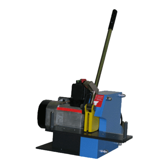
Page 10: Design
11 Upper Hexagon Head Bolt 2 Blade Protection 7 Bending Bolt 12 Lower Hexagon Head Bolt 3 Brake Motor 8 Main Switch 13 Electric Motor 4 Pedal Switch 9 Handle 5 Hand Lever 10 Holding Disk UNIFLEX-Hydraulik – 10 – www.uniflex.de... -
Page 11: Chapter 4 Commissioning
The work bench must be level. The cutting support should go further than the desk so the hose can be guided towards the cutting knife or the round brush freely (EM 3.4 DC; EM 3.2 Ecoline). UNIFLEX-Hydraulik – 11 – www.uniflex.de... -
Page 12: Connecting The Electric Supply (Alternating Current)
12 VDC / 24 VDC Continuous Current, To screw • tightly. No Gelbattery. • Look for an adequacy engine power of the • + Pol current generator. Suitable fuse: 250 A: 12 VDC inactive • : 150 A: 24 VDC inactive - Pol UNIFLEX-Hydraulik – 12 – www.uniflex.de... -
Page 13: Exhaust
Commissioning the EM 3.2 Ecoline The UNIFLEX EM 3 Ecoline / EM 3.2 Ecoline has been designed as a table machine and should be used on a solid work bench. Two bore holes of Ø 9 mm located in the chassis (refer to drawing) should be used in case of a stationary mounting. -
Page 14: Operating The Machine
Holding pins / Guides Picture A z.B DN 38 Holding pins / Guides Picture B z.B DN 16 Picture C Attention: Never cut without bending. Attention: The hoselength must be minimum outside of the Bending Bolt (Guides). UNIFLEX-Hydraulik – 14 – www.uniflex.de... - Page 15 Hand lever or foot pedal should be opened shortly to continue cutting slowly. With pneumatic machines control the air pressure according to hose thickness. Attention: When cutting inappropriately the cutting blade can anneal and break Note: Cracked or deformed cutting blades need to be exchanged immediately. UNIFLEX-Hydraulik – 15 – www.uniflex.de...
-
Page 16: Cutting Of Hoses
The blade protection opens and closes automatically with each cutting process. Warning: Never operate the blade protection by hand! Cutting without pneumatic feeder ( EM 1 / EM 2 / EM 3.3 / EM 3.2 Ecoline ) Prepare the machine as shown above. •... -
Page 17: Brushing
• Use both hands to turn the hose over the skiving mandrel. When the skiving process is finished, carefully • remove the hose. Turn the machine off by operating the OFF-Switch «O». • EM 2 UNIFLEX-Hydraulik – 17 – www.uniflex.de... -
Page 18: Chapter 6 Maintenance
(Danger of explosion)! Attention: Do not remove safety installations! Attention: Check the functioning of the emergency stop button regularly! Attention: The machine needs to be switched off on the main switch during all maintenance works! UNIFLEX-Hydraulik – 18 – www.uniflex.de... -
Page 19: Daily Maintenance
Annually Maintenance: Check the security settings and functioning elements of the machine. • Clean the machine and if required the attached suction line. • UNIFLEX-Hydraulik – 19 – www.uniflex.de... -
Page 20: Disassembling The Cutting Blade
Assembling the cutting blade The assembly of the cutting blade is done in reverse order. Warning: Make sure that motor and blade rotate in the same direction, otherwise there ist he danger of damaging the blade during cutting. UNIFLEX-Hydraulik – 20 – www.uniflex.de... -
Page 21: Take Off The Round Brush
Secure the drive shaft against rotating. (The rotating direction of the nut equals to the rotating direction of the round brush). Take nut and flange off and remove the round brush. Mounting the round brush To mount the round brush, do the same as is described above in reverse order. UNIFLEX-Hydraulik – 21 – www.uniflex.de... -
Page 22: Change Of The Driving Disk Em 3.4 Dc
Take care that the engine sprocket meshes with the driving disk. Remount and tighten the engine screws. If distance plates had been fitted between the engine and the chassis, they must be inserted at the same position. UNIFLEX-Hydraulik – 22 – www.uniflex.de... -
Page 23: Anhang / Appendix / Apèndice / Appendice
TM 160 x 2,5 x 20 Trennmesser Cutting blade Lame de coupe Cuchilla de corte 303.103.3 Gelenk Joint Pièce d’articulation Articulación 303.101.3 Chassis Chassis Châssis Armazón 303.102.3 Schneidplatte Cutting Support Support de coupe Placa de corte UNIFLEX-Hydraulik – 23 – www.uniflex.de... - Page 24 Perno de flexión 300.001 Gummimetallpuffer Rubber-Metal-Buffer Tampon caoutchouc Cojín metal-caucho métal 300.088 Hauptschalter Main Switch Interrupteur principal Interruptor principal Ohne Bild / 300.017 Flanschscheibensatz Flange disc set Flasque set Juego de discos de brida UNIFLEX-Hydraulik – 24 – www.uniflex.de Pas d´ image...
- Page 25 Cartouche fusible Tapón de fusible Ohne Bild / 311.059 Motor Start-Kabel EM3.3DC Motor start cable EM3.3DC Câble starter EM3.3DC Cable de arranque EM3.3DC Pas d´ image 311.027 Zugfeder Extension spring Ressort de traction Resorte regulator UNIFLEX-Hydraulik – 25 – www.uniflex.de...
- Page 26 Protector de cuchilla 304.2001 Biegebolzen Bending Bolt Pige de cintrage Perno de flexión See table Schalter Switch Interrupteur Interruptor Ohne Bild / 300.017 Flanschscheibensatz Flange disc set Flasque set Juego de discos de brida Pas d´ image UNIFLEX-Hydraulik – 26 – www.uniflex.de...
-
Page 27: Em 3.2 Ecoline
EM 3.2 Ecoline UNIFLEX-Hydraulik – 27 – www.uniflex.de... - Page 28 Señal de aviso: Usar tragen and Ear protection du port de lunettes de protección ocular y de oído sécurité et d’un casque anti-bruit Ohne Bild / 716.4 Warnschild Warning Sign Signal d’avertissement Señal de aviso Pas d´ image UNIFLEX-Hydraulik – 28 – www.uniflex.de...
- Page 29 Interruptor guardamotor with. Socket 230V-1Ph 230V-1~ Nur mit Motor / only with Haltescheibe Holding disc Rondelle de fixation Disco de fijación Motor Nur mit Motor / only with Flanschscheibe Flange disc Flasque Disco de brida Motor UNIFLEX-Hydraulik – 29 – www.uniflex.de...
-
Page 30: Wo Sie Ersatzteile Bestellen Können / Where To Obtain Spare Parts
Seriennummer / Serial-Number / Le numéro de série / Número de serie • Baujahr / Year of production / L’année de construction / Año de construcción • Spannung / Voltage / La tension de service / Voltaje • UNIFLEX-Hydraulik – 30 – www.uniflex.de... -
Page 31: Elektroplan / Electric Circuit Diagram / Schéma Électrique / Esquema De Circuitos Eléctricos
Elektroplan / Electric Circuit Diagram / Schéma électrique / Esquema de circuitos eléctricos EM 2 (220 / 230 V, 50 / 60 Hz, 3~) UNIFLEX-Hydraulik – 31 – www.uniflex.de... - Page 32 EM 2 (400 V, 50 / 60 Hz, 3~) UNIFLEX-Hydraulik – 32 – www.uniflex.de...
- Page 33 EM 3.4 DC (24V) UNIFLEX-Hydraulik – 33 – www.uniflex.de...
-
Page 34: Em 3.4 Dc (12Vdc / 24Vdc)
EM 3.4 DC (12VDC / 24VDC) UNIFLEX-Hydraulik – 34 – www.uniflex.de... -
Page 35: Em 3.2 Ecoline
EM 3.2 Ecoline UNIFLEX-Hydraulik – 35 – www.uniflex.de... - Page 36 EM 3.3 (220-230 V, 60 Hz, 3~) UNIFLEX-Hydraulik – 36 – www.uniflex.de...
- Page 37 EM 3.3 (440-460 V, 60 Hz, 3~ / 380-415 V, 50 Hz, 3~) UNIFLEX-Hydraulik – 37 – www.uniflex.de...
-
Page 38: Wartungsbuch / Maintenance Book / Carnet D'entretien / Libro De Mantenimiento / Libretto Die Manutenzione / Onderhoud Boek
Wartungsbuch / Maintenance book / Carnet d’entretien / Libro de mantenimiento / Libretto die manutenzione / Onderhoud boek UNIFLEX-Hydraulik – 38 – www.uniflex.de... -
Page 39: Erklärung Des Geschulten Personals / Declaration Of Trained Personnel
I also declare that I have read and understood this operating manual in full. Par la présente, je déclare avoir suivi une formation dans l’entreprise pour m’initier à l’utilisation de la machine UNIFLEX et avoir été informé de tous les détails liés à la sécurité. - Page 40 Note: UNIFLEX-Hydraulik – 40 – www.uniflex.de...
Need help?
Do you have a question about the EM 1 and is the answer not in the manual?
Questions and answers