
Related Manuals for Gardner Denver Sutorbilt Legend P Series


Summary of Contents for Gardner Denver Sutorbilt Legend P Series
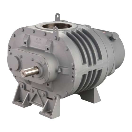
- Page 1 PARTS LIST OPERATING AND SERVICE MANUAL LEGEND “P” SERIES BLOWERS 2” – 5” GEAR DIAMETER Models GAA_ _ P _ GAB_ _ P _ GAC_ _ P _ GAE_ _ P _ SB-7-621 Version 06 April 2, 2007...
-
Page 3: Maintain Blower Reliability And Performance
Rely upon the knowledge and experience of your AUTHORIZED DISTRIBUTOR and let them assist you in making the proper parts selection for your blower. For the location of your local authorized Gardner Denver blower distributor refer to the yellow pages of your phone directory, check the Web site at www.gardnerdenver.com... - Page 4 5 Gallon Pail 28H99 55 Gallon Drum 28H100 Drive End AEON PD Grease Description Part Number Case/10 Tubes 28H283 Call your local Sutorbilt Distributor to place your order for Gardner Denver lubricants. Your Authorized Gardner Denver Distributor is: SB-7-621 Page 3...
-
Page 5: Foreword
FOREWORD Sutorbilt blowers are the result of advanced engineering and skilled manufacturing. To be assured of receiving maximum service from this machine, the owner must exercise care in its operation and maintenance. This book is written to give the operator and maintenance department essential information for day-to-day operation, maintenance and adjustment. -
Page 6: Safety Precautions
SAFETY PRECAUTIONS Safety is everybody’s business and is based on your use of good common sense. All situations or circumstances cannot always be predicted and covered by established rules. Therefore, use your past experience, watch out for safety hazards and be cautious. Some general safety precautions are given below: Failure to observe these notices could result in injury to or death of personnel. -
Page 7: Table Of Contents
TABLE OF CONTENTS Maintain Blower Reliability And Performance......................2 Foreword ..................................4 Safety Precautions..............................5 Sutorbilt Legend Series Blowers Matrix/Menu......................8 Introduction ................................9 Section 1, Equipment Check............................ 10 Section 2, Installation............................... 12 Section 3, Lubrication .............................. 17 Section 4, Operation ..............................20 Section 5, Special Tools Required........................... - Page 8 INDEX Aeon PD Food Grade Lubricant ........18 Mechanical Seals Only ..........28, 29 Aeon PD Synthetic Lubricant.......... 18 Mounting Configurations..........12 Air Filters And Filter Silencers ........16 Assembly Instructions, Section 7 ........28 Operation, Section 4............20 Blower Startup Checklist..........21 Parts List, Section 8............
-
Page 9: Sutorbilt Legend Series Blowers Matrix/Menu
SUTORBILT LEGEND SERIES BLOWERS MATRIX/MENU NOTICE TO CUSTOMER – To find the construction options for Your blower unit, FILL IN THE BALANCE OF LETTERS OR __ __ __ __ __ __ __ NUMBERS FROM YOUR UNIT NAMEPLATE COLUMN NUMBER FOLLOW THE LINE DOWN AND OVER FROM EACH SPACE THUS FILLED IN TO FIND THE APPROPRICATE CONSTRUCTION OPTION WITH WHICH YOUR MACHINE IS EQUIPPED. -
Page 10: Introduction
Your Sutorbilt blower is a precision engineered blower that has been carefully manufactured and thoroughly tested at the state-of the art Gardner Denver Blower Factory in Sedalia, Missouri. As with other precision machinery, there are several relatively simple installation, operation and maintenance procedures that you must observe to assure optimum blower performance. -
Page 11: Section 1, Equipment Check
STORAGE Your Gardner Denver Blower was packaged at the factory with adequate protection to permit normal storage for up to six (6) months. If the unit is to be stored under adverse conditions or for extended periods of time, the following additional measures should be taken to prevent damage. - Page 12 Blower inlet and outlet are temporarily capped to keep out dirt and other contaminants during shipment. These covers must be removed before start-up. The internal surfaces of all Sutorbilt units are mist sprayed with a rust preventative to protect the machine during shipment.
-
Page 13: Section 2, Installation
SECTION 2 INSTALLATION LOCATION Install the blower in a well lit, clean dry place with plenty of room for inspection and maintenance. FOUNDATIONS For permanent installation we recommend concrete foundations be provided, and the equipment should be grouted to the concrete. It is necessary that a suitable base be used, such as a steel combination base under blower and motor, or a separate sole plate under each. -
Page 14: Drive Installation
FIGURE 2-1 – BLOWER MOUNTING CONFIGURATIONS 4. Secure the mounting feet capscrews to the torque value in Figure 7-8, page 34. NOTICE When changing mounting configuration, it may be necessary to reposition vent plug (B), and drain plug (A). Refer to Figure 3-1, page 17, for correct location. DRIVE INSTALLATION When selecting a V-belt drive, check to be sure the shaft overhung load limitation is not exceeded. -
Page 15: Piping
Exceeding overhung load limitations leads to unwarrantable premature bearing failure and shaft breakage. The location of the sheave on the blower shaft greatly affects the stress in the shaft. The optimum blower sheave positioning is as close as possible to the blower drive cover, not to exceed dimension “C” in Drive Shaft Illustration, FIGURE 2-2, page 15 The calculated shaft moment must not exceed the maximum allowable moment listed in Maximum Allowable Moment Chart, FIGURE 2-2 page 15. -
Page 16: Figure 2-2 - Belt Drive Overhung Load Calculations
Maximum Gear Dimensions Allowable Diameter (Inches) Moment (Inches) (LB-IN) (Max) 2.76 2.88 3.49 1.10 3.90 1.40 1245 MAXIMUM ALLOWABLE MOMENT DRIVE SHAFT ILLUSTRATION 0.000 1.000 0.250 0.966 0.500 0.926 0.750 0.879 1.000 0.823 1.250 0.751 0.025 0.997 0.275 0.962 0.525 0.922 0.775 0.874... -
Page 17: Air Filters And Filter Silencers
AIR FILTERS AND FILTER SILENCERS Servicing the air filters is one of the most important maintenance operations to be performed to insure long blower life. Servicing frequency of filter elements is not time predictable. A differential pressure indicator, with a continuous gauge reading, should be installed across the inlet filter. -
Page 18: Section 3, Lubrication
Drive end bearings are grease lubricated at the factory with Lithium Complex based grease. For relubrication, use Gardner Denver AEON PD Grease, Part Number 28H283. AEON PD Grease is a high temperature, high performance grease that is formulated with antiwear additives to provide superior service under the severe operating conditions of positive displacement blowers. -
Page 19: Aeon Pd Food Grade Lubricant
RECOMMENDED LUBRICANT Gear Diameter Vertical Horizontal 2” 1/4 PT. 1/2 PT. 3” 1/3 PT. 2/3 PT. 4” 3/4 PT. 1 PT. 5” 1 PT. 2-1/4 PT. FIGURE 3-2 – APPROXIMATE OIL CAPACITIES The factory recommended lubricant is AEON PD Synthetic Lubricant. AEON PD is formulated especially for positive displacement blowers to provide maximum protection at any temperature. -
Page 20: Figure 3-4 - Lubrication Recommendation
Do not overfill as this will tend to cause excessive heating of the gears and may damage the unit. AEON PD Synthetic Lubricant should be drained after 6000 hours of operation. Re-fill with fresh AEON PD oil. If mineral oil is used, perform the above oil—change maintenance every 1500 hours. Recommended service intervals are for normal blower operating conditions. -
Page 21: Section 4, Operation
SECTION 4 OPERATION Future operating problems can be avoided if proper precautions are observed when the equipment is first put into service. Before starting under power, the blower should be turned over by hand to make certain there is not binding or internal contact. -
Page 22: Blower Startup Checklist
BLOWER STARTUP CHECKLIST This startup procedure should be followed during the initial installation and after any shutdown periods or after the blower has been worked on or moved to new location. It is suggested that the steps be followed in sequence and checked off (v) in the boxes provided. -
Page 23: Safety Precautions
SAFETY PRECAUTIONS Do not operate blower with open inlet or outlet port. Do not exceed specified vacuum or pressure limitations. Do not operate above or below recommended blower speed range. Blower is not to be used where non-sparking equipment is specified. Do not operate without belt guard or coupling shield. -
Page 24: Section 5, Special Tools Required
SECTION 5 MAINTENANCE ORDER SPECIAL TOOLS BY PART NUMBER. SEE PAGE 1 FOR ORDERING INSTRUCTIONS. Unit Size Part Number 2” 200GAA340 3” 201GAA340 4” 202GAA340 5” 203GAA340 FIGURE 5-1 – PULLER PLATE FIGURE 5-2 – GEAR DRIVER – 208GAA074 SB-7-621 Page 23... -
Page 25: Figure 5-3 - Mechanical Seal Installation Tool
Unit Size Part Number 2” 204GAA074 3” 205GAA074 4” 206GAA074 5” 207GAA074 FIGURE 5-3 – MECHANICAL SEAL INSTALLATION TOOL Unit Size Part Number 2” 200GAA074 3” 201GAA074 4” 202GAA074 5” 203GAA074 FIGURE 5-4 – BEARING PRESS TOOL – MECHANICAL SEAL UNITS SB-7-621 Page 24... -
Page 26: Section 6, Disassembly Instructions
SECTION 6 DISASSEMBLY INSTRUCTIONS NOTICE Numbers in parentheses ( ) refer to key numbers in assembly drawings on pages 35, 37, 39 and 41. 1. Drain oil from gear case by removing drain plug (4). 2. Remove the socket head bolts (5) from the gear cover (3). 3. -
Page 27: Figure 6-3 - Disassembly Illustrations
FIGURE 6-4 FIGURE 6-3 NOTICE If backlash is above the specified limit, the gears are not necessarily unusable. Excessive play could be caused by worn bearings. If timing gears appear to be reusable, match marktiming gear toothmesh by making small punch marks on the ends of meshing gear teeth with a pin punch and hammer (see FIGURE 6-2, page 25). -
Page 28: Figure 6-6 - Disassembly Illustrations
Remove mounting foot (17) from the drive headplate (24) by removing the capscrews (16). Remove the capscrews (21) which secure the drive headplate (24) to the impeller case (22). 10. Using the puller plate shown on page 23, bolt to the drive headplate using the tapped holes used to secure the drive cover. -
Page 29: Section 7, Assembly Instructions
SECTION 7 ASSEMBLY INSTRUCTIONS NOTICE Numbers in parentheses ( ) refer to key numbers in assembly drawings on pages 35, 37, 39 and 41. 1. Make sure all metallic parts are clean and free of any nicks or burrs. 2. Lubricate the outside diameter of the lip seal (15) with a light oil or grease. Install seals in both the drive headplate (24) and gear headplate (18). -
Page 30: Figure 7-2 - Assembly Illustrations
FIGURE 7-3 FIGURE 7-2 3. Assemble gear headplate (18) and mounting foot (17) to the impeller case with cap screws (21) and where the mounting foot is secured to the headplate use capscrews (16). The two positioning dowel pins (19) will ensure proper alignment of the headplate and impeller case. -
Page 31: Figure 7-4 - Assembly Illustrations
CLEARANCES FOR STANDARD UNITS ONLY TOTAL END CLEARANCE .006-.009 0.007-0.011 0.007-0.011 0.007-0.011 IMPELLER TO GEAR HEADPLATE .003-.004 0.003-0.005 0.003-0.005 0.003-0.005 IMPELLER TIMING (A-A) (C-C) .005-.008 0.005-0.007 .006-.008 0.006-0.008 .007-.010 .007-.010 .008-.010 TIP TO CASE CLEARANCE (B-B) 0.002 min. 0.002 min. 0.002 min. -
Page 32: Installing The Timing Gears
These impeller-to-impeller and impeller-to-case clearances are extremely critical. Even though the blower may turn freely by hand when cold, under operating conditions, the parts expand, and the rotors are subject to slight defection. If the clearances are not sufficient, the impellers may contact each other or the housing with destructive results. -
Page 33: Setting Impeller End Clearances
NOTICE If gears are being replaced, taper pin holes must be drilled after the gears are correctly positioned. Be careful not to let cuttings drop behind the gears and contaminate the bearings. Be careful not to let cuttings drop behind the gears and contaminate the bearings. F. -
Page 34: Figure 7-6 - Assembly Illustrations
FIGURE 7-6 FIGURE 7-7 NOTICE Check the clearance over the entire width of the impeller and consider the tightest spot. B. Divide the total end clearance by 3 and distribute approximately 1/3 on the gear end and the remaining 2/3 on the drive end. C. -
Page 35: Figure 7-8 - Torque (Ft-Lbs)
16. Replace drive shaft grease seal (31) in the drive end cover (29). The seal lip should always face towards the bearing or lubricant. Pack bearing cavities with recommended grease and secure drive cover with capscrews (30) to drive headplate. Refer to FIGURE 7-8 for torque specifications. Exercise care not to damage the seal lip as it passes over the shaft keyway. -
Page 36: Section 8, Parts List
SECTION 8 PARTS LIST 300GAA810-C (Ref. Drawing) SB-7-621 Page 35... - Page 37 Order by Part Number and Description. Reference Numbers are for your convenience only. MODEL GAA Ref. Size -- 2M Size -- 2L Description Req’d GAAM_P_ GAAL_P_ NAMEPLATE............... 302GAA496 302GAA496 OIL LEVEL PLUG............64AC1 64AC1 GEAR CASE..............900893022801 900893022801 DRAIN PLUG............... 64AC1 64AC1 SCREW--GEAR CASE TO BEARING HOUSING ..
- Page 38 200GAB810-E (Ref. Drawing) SB-7-621 Page 37...
- Page 39 Order by Part Number and Description. Reference Numbers are for your convenience only. MODEL GAB Ref. Size-- 3H Size -- 3M Size -- 3L Description Req’d GABH_P_ GABM_P_ GABL_P_ NAMEPLATE................302GAA496 302GAA496 302GAA496 OIL LEVEL PLUG..............64AC2 64AC2 64AC2 GEAR CASE................900873032901 900873032901 900873032901...
- Page 40 300GAC810-B (Ref. Drawing) SB-7-621 Page 39...
- Page 41 Order by Part Number and Description. Reference Numbers are for your convenience only. MODEL GAC Ref. Size -- 4H Size -- 4M Size -- 4L Description Req’d GACH_P_ GACM_P_ GACL_P_ NAMEPLATE ................302GAA496 302GAA496 302GAA496 PLUG FOR ALTERNATE OIL LEVEL CONN......64AC3 64AC3 64AC3...
- Page 42 300GAC810-B (Ref. Drawing) SB-7-621 Page 41...
- Page 43 Order by Part Number and Description. Reference Numbers are for your convenience only. MODEL GAE Ref. Size -- 5H Size -- 5M Size -- 5L Description Req’d GAEH_P_ GAEM_P_ GAEL_P_ NAMEPLATE ................301GAE496 301GAE496 301GAE496 PLUG FOR ALTERNATE OIL LEVEL CONN......64AC3 64AC3 64AC3...
- Page 44 SB-7-621 Page 43...
-
Page 45: Warranty
For additional information contact your local representative or Gardner Denver, 1800 Gardner Expressway, Quincy, IL 62305 Customer Service Department Telephone: (800) 682-9868 Fax: (217) 221-8780 Sales and Service in all major cities. www.gardnerdenver.com pd.blowers@gardnerdenver.com © 2007 Gardner Denver, Inc. Litho in U.S.A. - Page 46 This document was created with Win2PDF available at http://www.win2pdf.com. The unregistered version of Win2PDF is for evaluation or non-commercial use only. This page will not be added after purchasing Win2PDF.
Need help?
Do you have a question about the Sutorbilt Legend P Series and is the answer not in the manual?
Questions and answers