Table of Contents
Advertisement
Contents
1 Introduction........................................................................................................................................................................................ 2
1.1 General characteristics ...................................................................................................................................................................... 2
2 Codes of instruments and accessories ................................................................................................................................................ 2
2.1 FCM* codes ...................................................................................................................................................................................... 2
2.2 Accessories ....................................................................................................................................................................................... 2
3 Buttons and displayed indications ..................................................................................................................................................... 3
3.1 Front panel........................................................................................................................................................................................ 3
4 Installation.......................................................................................................................................................................................... 4
4.1 Mounting the instrument ................................................................................................................................................................... 4
4.2 Electrical connections........................................................................................................................................................................ 4
5 Functions ............................................................................................................................................................................................ 5
5.1 Serial option...................................................................................................................................................................................... 5
6 Programming and configuring the FCM* ......................................................................................................................................... 6
6.1 Standard configuration....................................................................................................................................................................... 6
6.2 Initialisation of FCM* instruments .................................................................................................................................................... 6
6.3 Auxiliary functions ............................................................................................................................................................................ 7
6.4 High and Low alarms (not available in slave mode) ........................................................................................................................... 8
6.5 Defrosting (not available in SLAVE mode)........................................................................................................................................ 8
6.6 Multifunction digital inputs ............................................................................................................................................................... 9
6.7 Multi-function digital output............................................................................................................................................................ 10
6.8 Extra LED indicators....................................................................................................................................................................... 10
7 Programming FCM controllers ....................................................................................................................................................... 11
7.1 Setting the set-point ("St" parameters) ............................................................................................................................................. 11
7.2 Accessing "P" parameters ................................................................................................................................................................ 11
7.3 Accessing "C" parameters................................................................................................................................................................ 11
7.4 Validity of the modifications............................................................................................................................................................ 12
7.5 Displaying the unit of measure ........................................................................................................................................................ 12
7.6 Setting min. and max. output values ................................................................................................................................................ 12
7.7 Factory-set parameters..................................................................................................................................................................... 13
7.8 Remote Control ............................................................................................................................................................................... 13
7.9 Technical specifications................................................................................................................................................................... 13
7.10 Description of the keypad .............................................................................................................................................................. 13
7.11 Using the remote control................................................................................................................................................................ 14
7.12 Setting the access code .................................................................................................................................................................. 14
8 Description of the parameters.......................................................................................................................................................... 15
8.1 Parameters concerning the set-point................................................................................................................................................. 15
8.2 Parameters concerning the analogue output...................................................................................................................................... 16
8.3 Parameters concerning inputs .......................................................................................................................................................... 18
8.4 Alarm parameters ............................................................................................................................................................................ 19
8.5 Parameters concerning digital inputs and output .............................................................................................................................. 20
8.6 Parameters concerning the unit of measure ...................................................................................................................................... 21
8.7 Parameters concerning defrost ......................................................................................................................................................... 23
8.8 Parameters concerning keypad and remote control ........................................................................................................................... 24
8.9 Parameters concerning serial connection .......................................................................................................................................... 25
9 Table of Parameters ......................................................................................................................................................................... 27
10 Alarms ............................................................................................................................................................................................ 31
11 Technical specifications.................................................................................................................................................................. 32
12 Wiring diagram .............................................................................................................................................................................. 33
12.1 Terminal block .............................................................................................................................................................................. 33
12.2 Power supply:................................................................................................................................................................................ 33
12.3 Connecting probes ......................................................................................................................................................................... 34
13 Dimensions...................................................................................................................................................................................... 35
FCM electronic regulator
1
Cod. +302235300 - Rel. 2.0 del 30/11/98
Advertisement
Table of Contents

Related Manuals for Carel FCM series


Summary of Contents for Carel FCM series
-
Page 1: Table Of Contents
Contents 1 Introduction......................................2 1.1 General characteristics ..................................2 2 Codes of instruments and accessories ..............................2 2.1 FCM* codes ...................................... 2 2.2 Accessories ....................................... 2 3 Buttons and displayed indications ..............................3 3.1 Front panel......................................3 4 Installation......................................4 4.1 Mounting the instrument ................................... -
Page 2: Introduction
Introduction The electronic controls of FCM series have been designed to manage the main physical values (temperature, pressure, humidity) in air- conditioning, refrigeration and heating units. General characteristics There are 3 models available, which differ according to the type of analogue input (probe). -
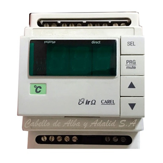
Page 3: Buttons And Displayed Indications
Buttons and displayed indications Front panel Fig. 1 1 - Display: • it displays the value of the connected probes or the status of the control, as programmed (parameter C33); • in the event of alarm, it displays the alarm code; •... -
Page 4: Installation
Installation Mounting the instrument Connect probes and power: probes can be placed up to 100 m distant from the controller provided that you use 1mm² cross-section, possibly shielded, cables to increase immunity against noises. 2) Program the control following the instructions in the “Programming” section. 3) Connect the actuators: the actuators should only be connected after having programmed the control. -
Page 5: Functions
Functions The output of the FCM* controller provides a continuous voltage signal ranging between 0 V and 10 V; the exact value depends on the measurement made by the connected probes, according to the selected operating mode and the programmed control parameters. Alternatively, the control output can be used to carry out On/Off regulation. -
Page 6: Programming And Configuring The Fcm
Programming and configuring the FCM* Standard configuration The FCM controls are supplied with the following default settings: FCM00NTC00: ÷ • NTC probes (range: -40°C 100°C); • display in degrees °C. FCM0001000: ÷ • temperature probes with 0 10 V voltage output; ÷... -
Page 7: Auxiliary Functions
Ü Ü C00=5 DIRECT(SET1) /DIRECT(SET2) mode through digital input This operating mode depends on the status of the digital input ID1: Ü ID1 not active (open) DIRECT operation with main set-point and differential (param. St1 and P01); Ü ID1 active (closed) DIRECT operation with secondary set-point and differential (param. -
Page 8: High And Low Alarms (Not Available In Slave Mode)
• • Second probe management (not available in slave mode) The value of the measurement actually used by the controller depends on the two probe inputs, and can be selected (parameter C19) keeping into consideration the following elements: • probe 1 (probe 2 not used); •... - Page 9 Fig.5 FCM electronic regulator Cod. +302235300 - Rel. 2.0 del 30/11/98...
-
Page 10: Multifunction Digital Inputs
Multifunction digital inputs The terminal block comes complete with two digital inputs which can be associated with two commands, whose function can be selected by using parameters C29 and C30. • automatically-reset alarm: when the contact opens, the analogue output is immediately forced to 0 V and the corresponding alarm is generated. -
Page 11: Programming Fcm Controllers
Programming FCM controllers There are three groups of parameters which allow you to customize the use of the FCM instrument, according to your specific application requirements: "C" Parameters or configuration parameters: are to be set at the very beginning, depending on the features of your FCM, its inputs and outputs. -
Page 12: Accessing "C" Parameters
Accessing "C" parameters 1. hold down together for about 5 seconds, until "00" appears on the display; after that digit the password; 2. press to introduce the password ("77"); 3. press to confirm the password. If the password is incorrect, the programming procedure will interrupt, otherwise "C00" will be displayed. -
Page 13: Factory-Set Parameters
Remote Control In order to make the programming procedure of the FMC easier, Carel suggests using the remote control, not only to program data from a remote position but also to set the most common and most used parameters quickly and easily. The remote control allows you to display and modify set-points and all P and C parameters from a distant point. -
Page 14: Using The Remote Control
· 1) goes from one parameter to the previous one; · 2) decreases the value of the displayed parameter (while setting the parameter values) 7.11 Using the remote control Access without code ENABLING THE FCM CONTROLLER TO RECEIVE INSTRUCTIONS FROM THE REMOTE CONTROL •... -
Page 15: Description Of The Parameters
Description of the parameters Parameters concerning the set-point St1: Set-point 1 (main) St1 is the most important parameter; it is used in any operating mode, except in SLAVE. Access: Ü Keypad: if C50=1, 3 or 4 direct access pressing Ü if C50=0 or 2 the parameter can only be displayed. -
Page 16: Parameters Concerning The Analogue Output
P02: Differential of St2 P02 defines the hysteresis of St2 (that is the width of the regulation zone). It is a relative value which can have the same value as St2 or can be set on its right or on its left. Access: Ü... - Page 17 C07: Cut-off C07 defines the threshold beyond which the analogue output disenergizes (0 V). It is expressed as a relative value and refers to the minimum output value. Access: Ü Keypad: if C50=1, 3 or 4 for 5” and password 77; Ü...
-
Page 18: Parameters Concerning Inputs
20 mA probes for temperature or humidity Default: C13 = 0 for FCM00NTC00, 1 for FCM0001000, 6 for FCM0002000. ÷ Note: CAREL 4 20 mA probes are connected according to the figures on page XXX, since it is expected Ω a 100 maximum load value resistance. - Page 19 C16: Maximum value of current or voltage inputs ÷ C16 indicates the value measured when the input is given its maximum possible signal, that is 10 V when using 0 10 V probes, 20 mA ÷ ÷ with 0 20 mA and 4 20 mA probes.
-
Page 20: Alarm Parameters
Alarm parameters P25: Low threshold alarm P25 identifies the threshold under which a Low (temperature, pressure, etc.) alarm is generated. P25 is an absolute value. Access: Ü Keypad: if C50=1, 3 or 4 press for 5”; Ü if C50=0 or 2 the parameter can only be displayed. -
Page 21: Parameters Concerning Digital Inputs And Output
Parameters concerning digital inputs and output C29: Multifunction digital input ID1 C29 indicates the function of the digital input ID1. Access: Ü Keypad: if C50=1, 3 or 4 for 5” and password 77; Ü if C50=0 or 2 the parameter can only be displayed.. Ü... -
Page 22: Parameters Concerning The Unit Of Measure
Parameters concerning the unit of measure C32: Displaying the unit of measure C32 defines if and when it is necessary to display the unit of measure. Access: Ü Keypad: if C50=1, 3 or 4 for 5” and password 77; Ü if C50=0 or 2 the parameter can only be displayed.. -
Page 23: Parameters Concerning Defrost
P38: Displaying the % value of the input of probe 1 The parameter can only be displayed. Access: Keypad: press for 5 seconds; Remote control: press “ENABLE” and Note: P38 has some meaning only in models FCM0001000 and FCM0002000 working in the SLAVE mode where it makes the instrument display the command signal in %. -
Page 24: Parameters Concerning Keypad And Remote Control
P43: Max. duration of defrost P43 defines the max. duration of a defrost cycle. Access: Ü Keypad: if C50=1, 3 or 4 press for 5”; Ü if C50=0 or 2 the parameter can only be displayed. Ü Remote control: if C50=0, 1 or 4 press “ENABLE”... -
Page 25: Parameters Concerning Serial Connection
C51: Code enabling the remote control C51 allows you to give each controller a code to access parameters via remote control. If your control panel comprises several instruments, press “ENABLE” on the remote control to give each instrument a different access code. Access: Ü... - Page 26 C55: Frame / page Depending on the communication protocol, C55 defines: • supervision: data structure (frame); • pLAN: the page of the device where data will be received. Access: Ü Keypad: if C50=1, 3 or 4 for 5 seconds and password 77; Ü...
-
Page 27: Table Of Parameters
Table of Parameters Parameter U.M. Nuovi PASSWORD PARAMETERS CONCERNING THE SET-POINT (*) Set-point 1 (main) °C r.H./bar °C (*) Set-point 2 (secondary) - parameter accessible only if C00=5, 6, 7, 8 r.H./bar Operating mode: 0= Slave direct 1= Slave reverse 2= Direct 3= Reverse 4= Dir. - Page 28 20 mA probes for T. or H. ÷ 20 mA probes for P. ÷ 7=Carel 4 20 mA probes for Temp. and Humidity C14* Type of refrigerant - accessible only when C13=2, 4, 6 0=unspecified refrigerant; 1=R22, 2=R404a, 3=R407, 4=R134a, 5=R410a, 6=R290 (propane), 7=NH 3 (ammonia) C15* Min.
- Page 29 Multi-function digital output (relay) - parameter not accessible when defrost is enabled (C00=8) 0=output not used (disenergized relay) 1=disenergized relay in the event of generic alarm 2=energized relay in the event of generic alarm 3=disenergized relay in the event of active analogue output 4=energized relay in the event of active analogue output 5=disenergized relay when the analogue output has its max.
- Page 30 PARAMETERS CONCERNING KEYPAD/REMOTE CONTROL Enabling Keypad and Remote control: 0=keypad disabled; rem.control: param. P and St1 can be modified, par. C can't be seen. 1=keypad enabled; rem. control: param. P and St can be modified, param. C can't be seen. 2= keypad disabled;...
-
Page 31: 10 Alarms
10 Alarms The instrument controls and constantly checks alarm conditions during unit operating. In the event of off-normal condition: • when not in the programming phase, the display shows a message that identifies the type of alarm (see table below). The alarm message is shown alternatively to the normally displayed parameter every two seconds;... -
Page 32: 11 Technical Specifications
Category II Class and structure of the Software Class A Ω Analogue inputs FCM00NTC00 2 for probes NTC CAREL 10 k at 25°C (response time depends on the type of component) ÷ FCM0001000 10 V inputs (min. response time 100 ms) ÷... -
Page 33: 12 Wiring Diagram
12 Wiring diagram 12.1 Terminal block Terminal Symbol Description G(+) Power supply (positive pole when dc voltage) G0(-) Power supply (negative pole when dc voltage) Cable shielding ÷ 10Vdc analogue output ÷ GND for 0 10Vdc analogue output +12V Auxiliary power supply Input probe 1 GND for input probe 1 +12V... -
Page 34: Connecting Probes
12.3 Connecting probes NTC Probes Generator 0÷10 V probes Potentiometer 0÷10 V probes (with separate external supply) (*) It is recommended to connect an 820Ω resistor in series Generator 0÷20mA o 4÷20mA probes (with separate external supply) FCM electronic regulator - Preliminary version Cod. -
Page 35: 13 Dimensions
Note: using a probe, it is possible to inhibit the R200 Ω resistance connection, if the 7-B1 and 10-B2 terminals are bridged. 13 Dimensions Carel reserves the right to modify the features of its products without prior notice. FCM electronic regulator - Preliminary version...
Need help?
Do you have a question about the FCM series and is the answer not in the manual?
Questions and answers