
Related Manuals for Esse-ti HELPY 2W-TL


Summary of Contents for Esse-ti HELPY 2W-TL
-
Page 1: Quick Guide
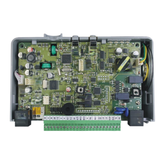
Alarm system for elevators compliant with the European Standard EN 81-28:2018 HELPY 2W-TL QUICK GUIDE 15/01/2019... - Page 2 DESCRIPTION Autodialer specifically designed for installation on car roof. Versions: Helpy 2W-TL comes with power supply and backup battery Helpy 2W-TL 12 V 12 V power supply Helpy 2W-TL Internal power-supply connector Built-in backup battery connector Reset pushbutton Alarm pushbutton...
- Page 3 Micro SD card slot RJ45 connector for GSM200-C module Terminal blocks Battery compartment door Helpy 2W-TL 12 V Reset pushbutton Alarm pushbutton Serial port for PC connection Built-in loudspeaker connector RJ11 connector for local telephone Jumper J16 for define the behaviour of output AI...
-
Page 4: Terminal Blocks
LEDs LED signalling alarm / periodical test call (yellow) LED signalling GSM200-C signal strength (green) LED signalling device status (red) LED signalling power supply status (blue) Terminal blocks 12 Vdc power supply input (14,5 Vdc power supply input if battery present) Negative pole Given alarm indicator light (NPN/PNP by means of J16) - Page 5 : before using this input disconnect the internal power-supply cable, if present, from the A connector in the picture at page 2 : can be connected to a block –, to the block +12 or to an external reference : allows to connect voltage free contact pushbuttons (NO or NC) or powered pushbuttons : allows to connect voltage free contacts (NO or NC) : free contact NO DESCRIPTION...
-
Page 6: Connecting The Telephone Line
CONNECTING THE TELEPHONE LINE PSTN line or universal GSM gateway Connect the ground terminal (indicated by ), to a ground socket in order to increase the telephone line protection. Connect the telephone line to terminal LTI. GSM200-C module ... - Page 7 TL’s built-in speaker unit or to another 2W speaker unit and allows to double it. The passive speaker unit can be installed at max. 6 m distance from Helpy 2W-TL (or from 2W speaker unit) by using a shielded cable.
- Page 8 Given alarm indicator light (light negative pole) AL1— Alarm input Auxiliary input / Alarm input / Filter input AL1+ Alarm input BUS — Bus for connecting Helpy 2W-TL BUS + Bus for connecting Helpy 2W-TL only for some models Page 8 CONNECTING THE SPEAKER UNITS...
- Page 9 Terminal blocks for connecting a passive speaker unit ALT2 Output for connecting the loudspeaker of a passive speaker unit MIC2 Input for connecting the microphone of a passive speaker unit or a single microphone — Negative Microphone DIP switch The DIP switch allows to assign an ID (01~16) to each 2W speaker unit connected to the bus.
- Page 10 CONNECTING THE EMERGENCY CALL BUTTONS Car pushbutton It is possible to connect (inside the elevator car) voltage free contact pushbuttons or powered pushbuttons. Connect, following one of the diagrams shown below, the car pushbutton. Voltage free contact pushbuttons Powered pushbuttons (12~24Vdc) – 2 solutions Page 10 CONNECTING THE EMERGENCY CALL BUTTONS...
- Page 11 Passive speaker unit pushbuttons In case of passive speaker units without built-in pushbutton it is possible to use voltage free contact pushbuttons (NO or NC). Connect, following the diagram shown below, the external pushbutton. 2W speaker unit pushbuttons It is possible to connect external pushbuttons (voltage free contact pushbuttons or powered pushbuttons) to 2W speaker units without built-in pushbutton.
- Page 12 (this solution is allowed only if the negative pole of Helpy 2W-TL is not connected to the negative pole of the lift) Page 12 CONNECTING THE EMERGENCY CALL BUTTONS...
- Page 13 CONNECTING THE FILTER INPUT Connect, following one of the diagrams shown below, the filter contact. Note: if a 2W speaker unit is installed in the cabin, it is possible to use the terminal block’s filter input of the speaker unit (AUX and –...
- Page 14 The RECEIVED ALARM INDICATOR LIGHT (green) switches on when the alarm call is answered. Connect, following the diagrams shown below, the indicator lights to the Helpy 2W-TL. Page 14 CONNECTING THE INDICATOR LIGHTS...
- Page 15 2W speaker unit indicator lights Some 2W speaker unit models come with built-in indicator lights. It is also possible to connect external indicator lights. Connect, following one of the diagrams shown below, the external indicator lights to the 2W speaker unit. CONNECTING THE INDICATOR LIGHTS Page 15...
-
Page 16: Other Connections
Connect the output RL1 (normally open contact) to the external device. ONNECTING THE AUXILIARY INPUTS Helpy 2W-TL It is possible to configure the AL2 input of Helpy 2W-TL as auxiliary input (normally open or closed). Connect the external contact to AL2 and – terminals. -
Page 17: Wiring Diagrams
WIRING DIAGRAMS IRING DIAGRAM WITH SPEAKER UNIT IN THE PIT WIRING DIAGRAMS Page 17... - Page 18 IRING DIAGRAM WITH PASSIVE SPEAKER UNIT IN THE ELEVATOR CAR BOTTOM Page 18 WIRING DIAGRAMS...
- Page 19 IRING DIAGRAM WITH LANDING FLOORS WIRING DIAGRAMS Page 19...
- Page 20 MINIMUM OPERATIONS TO VERIFY PROPER INSTALLATION 1. PROGRAMMING Access to programming: lift the local telephone handset and dial The programming activated message will be heard. Only if GSM200-C module is present: dial Program a telephone number for the emergency-call alarm: dial <telephone number>...
-
Page 21: Resetting The Alarm
Answer by the called party. Press If the reset input is not closed within 6 hours, the alarm is automatically ended. Note: the reset input can be configured with the “Helpy 2W-TL inputs setting” programming (code 55). MINIMUM OPERATIONS TO VERIFY PROPER INSTALLATION... -
Page 22: Using The Reset Button
* <Password> #. Pressing longer (10 seconds) Allows to reset the device. By pressing longer, the Helpy 2W-TL will be re-started with no need to disconnect the power supply. Note: it is also possible to reset the device through the code 995*0#. -
Page 23: Basic Programming
< INSTALLER or OPERATOR PASSWORD > EXITING THE PROGRAMMING (factory default: SOURCE RECEIVER emergency- — call button battery USER alarms * periodic automatic test ESSE-TI call * 2W speaker … unit connection (X..X = TELEPHONE failure alarm telephone (position NUMBERS number, from 01 to (INST) SIM card max. -
Page 24: Listen To Messages
MESSAGES (record) (hang up) (INST) courtesy message (max. 25 s) identification LISTEN TO message MESSAGES (listen) (INST/OPER) courtesy message HELPY 2W-TL BUILT-IN (ID, from 01 to 99; SPEAKER UNIT 01=built-in speaker unit used for the car) (INST) Page 24 PROGRAMMING... -
Page 25: Low Battery Alarm
AUTOMATIC TEST automatic test disabled DATA Automatic (INST) automatic test enabled (EN 81-28:2018) test alarm automatic test enabled (EN 81-28:2004) Make a test call manually PROTOCOLS Esse-ti IDENTIFICATION … (identification code) CODE P100 (INST) SPEAKER UNITS loudspeaker microphone VOLUME speaker unit ID... -
Page 26: Advanced Programming
(0=normally closed OPEN/CLOSED 1=normally open) 1=normally open) (INST) AL2=alarm input / IN1=filter input AL2=auxiliary input / IN1=filter input HELPY 2W-TL INPUTS SETTING AL2=reset input / IN1=filter input (INST) AL2=alarm input / IN1=reset input AL2=auxiliary input / IN1=reset input 2W SPEAKER... - Page 27 ADVANCED PROGRAMMING NO EXTERNAL POWER SUPPLY disabled alarm ALARM (only with built- enabled alarm with XX minutes delay in power supply) (from 01 to 99) (INST) DIAGNOSTIC disabled alarm ALARM (INST) enabled alarm 2W SPEAKER disabled alarm UNIT CONNECTION FAILURE ALARM enabled alarm (INST) SIM CARD...
- Page 28 ADVANCED PROGRAMMING automatic reset ALARM RESET MODE alarm reset by “End alarm” code (INST) automatic reset with local acknowledgement “PLAY IDENTIFICATION … (from 1 to 3 digits; factory default 5) MESSAGE” CODE (INST) “HANDSFREE ACTIVATION” … (from 1 to 3 digits; factory default 0) CODE (INST) “END ALARM”...
-
Page 29: Relay Setting
ADVANCED PROGRAMMING NUMBER OF CALLS TO THE SAME NUMBER (calls, from 1 to 9) FOR EACH CYCLE (INST) CALL CYCLES FOR TECHNOLOGICAL ALARMS AND (cycles, from 1 to 9; 0=10 cycles; factory default 3) TEST CALLS (INST) CALL CYCLES FOR EMERGENCY CALL (cycles, from 1 to 9;... - Page 30 INTERMITTENCE (INST) intermittent (500 ms ON / 500 ms OFF) DTMF DTMF generated by GSM network GENERATOR SETTING WITH DTMF generated by Helpy 2W-TL GSM200-C (DTMF duration=X*50ms; from 1 to 9; (INST) factory default 2) LISTEN TO THE Digits Quality...
- Page 31 Programming via e-stant software It is possible to program Helpy 2W-TL via computer by using the USB/serial proprietary cable and the dedicated e-stant software. e-stant software also allows to: - update the firmware of the Helpy 2W-TL - customize the messages of the Helpy 2W-TL - set a micro SD card to use for programming, customizing the messages and updating the firmware of the Helpy 2W-TL.
-
Page 32: Notification Message Format
Programming via SMS (only with GSM200-C) Only with the module GSM200-C, all parameters programmable locally by the local telephone may also be set via SMS. Programming via SMS is possible by any mobile phone or other device supporting SMS. An SMS notifying the programming was performed is sent by the Helpy 2W- TL to the number that sent the programming. -
Page 33: Local Use
<TELEPHONE NUMBER> DOOR OPENER RELAY Use remotely with Helpy 2W-TL at rest Call Helpy 2W-TL and wait for a response. Listen to the elevator identification message, if present. Dial: to speak with the cabin speaker unit (ID 01) - Page 34 <password> (factory default: ) to access programming. All of the programming and functions below can now be performed: USE REMOTELY WITH HELPY 2W-TL AT REST PROGRAMMING … CABIN SPEAKER UNIT (ID 01 SPEAKER UNIT (ID 02) CONVERSATION WITH THE...
- Page 35 SIGNALS LED signalling alarm / periodical test call (yellow) Emergency-call alarm Emergency call alarm suspended Other alarms - Test call LED signalling GSM200-C signal strength (green) No signal Low signal level Medium signal level Good signal level High signal level SIGNALS Page 35...
- Page 36 LED signalling device status (red) Normal operation (no alarm) Alarm Voice connection Battery disconnected or low battery (max. 1-hour operation in idle state) 2W speaker unit connection error or bus problem Absence of telephone line Button failure Page 36 SIGNALS...
- Page 37 LED signalling power supply status (blue) The external power supply is connected and the battery has max capacity charge The external power supply is connected and the battery has good capacity charge The external power supply is connected and the battery has medium capacity charge The external power supply is connected and the battery has low capacity charge...
- Page 38 Given alarm indicator light (yellow) Alarm Received alarm indicator light (green) Voice connection Missed test call notification The Given alarm indicator light and the Received alarm indicator light flash in opposition to indicate the failure of the automatic test call. The flashing sequence ends after the next successful test call or emergency call.
-
Page 39: Eu Declaration Of Conformity
NOTE EU Declaration of Conformity Hereby, Esse-ti S.r.l. declares that the equipment type Helpy 2W-TL is in compliance with Directives 2014/30/EU - 2014/33/EU - 2014/35/EU. The full text of the EU declaration of conformity is available from the following Internet address: https://www.esse-ti.it/en/dichiarazioni-di-conformita... - Page 40 Esse-ti S.r.l. Via G. Capodaglio, 9 62019 Recanati (MC) – ITALY Tel. +39 071 7506066 Fax +39 071 7506057 www.esse-ti.it support@esse-ti.it...
Need help?
Do you have a question about the HELPY 2W-TL and is the answer not in the manual?
Questions and answers