Precision Planting 20/20 SeedSense Operator's Manual
Hide thumbs
Also See for 20/20 SeedSense:
- Operator's manual (78 pages) ,
- Operator's manual (65 pages) ,
- Setup manual (8 pages)
Table of Contents
Advertisement
Quick Links
Advertisement
Table of Contents

Related Manuals for Precision Planting 20/20 SeedSense


Summary of Contents for Precision Planting 20/20 SeedSense
- Page 1 955125_02 11/10...
-
Page 2: Table Of Contents
Table of Contents Legal Statements & Safety Warnings ........................System Requirements ............................... Quick Start Quide ............................... Operator’s Guide Understanding the Dashboard Buttons Population............................Singulation............................Good Spacing............................ Down Force............................Skips/Multiples..........................Acre Counters..........................Vacuum............................Hex Shaft............................Good Ride............................Loss per Acre..........................Seed Spacing ..........................Record Memo.......................... - Page 3 Table of Contents Delete Coverage Map........................Selecting Client or Farm......................23-26 Editing Field Name........................23-26 Enter a field entrance........................ 23-26 Enter Field Number, Tillage, Acres..................... 23-26 Configuring Population Targets Single Setting Target........................Variable Rate Targets........................Specific Row Targets........................Row Assignments........................... Configuring Crops and Hybrids Selecting Varieties..........................
- Page 4 Troubleshooting Steps..........................100-119 Wiring Diagrams........................... Mapping Guide Using the PC Setup Tool..........................Field Operations Viewer (by Mapshots)....................Driver Installation........................122,123 Viewer Installation......................... 123,124 125-133 Using the Viewer........................Precision Planting Viewer (by Farmworks) Software Installation......................134-137 Farmworks Tutorials......................138-143 955125_02 11/10...
-
Page 5: Legal Statements & Safety Warnings
Precision Planting is not liable for any failures to the system or planting loss due to decisions made from the information presented on the 20/20 SeedSense. -
Page 6: System Requirements
System Requirements Power Supply The 20/20 system uses both a switched power source and a constant unswitched power source. By using the constant source, the system will maintain power to save data and safely shut down if the ignition is suddenly shut off. By using the switched or keyed source, the 20/20 will turn itself off to keep from draining the battery if the system is left on after the ignition is shut off. -
Page 7: Quick Start Quide
Quick Start Guide Step 1: Cab Installation Begin installing your 2020 SeedSense by mounting the display unit in the cab. Next, connect the display unit to the tractor cable and the tractor cable to power. Now connect the GPS receiver to the tractor cable and mount the GPS receiver to the cab roof. Run the tractor cable out the back of the tractor down to the planter hitch. - Page 8 Notes 955125_02 11/10...
-
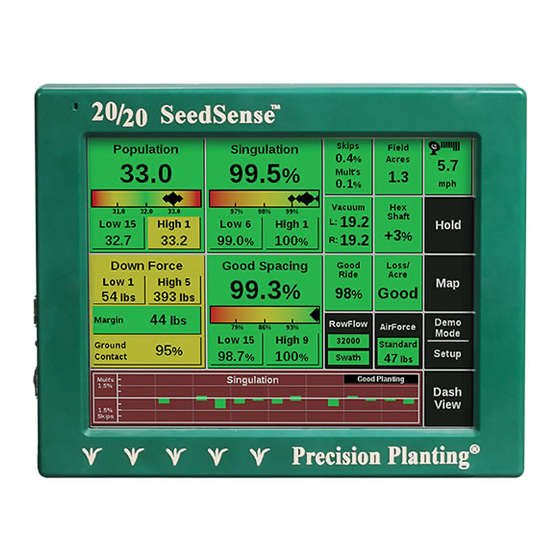
Page 9: Population
20/20 SeedSense. The dashboard screen displays the current planter average for the measurements taken by the 20/20 SeedSense in an easy to read, easy to navigate format. The columns outlined in white are configurable and can display a variety of measurements. -
Page 10: Skips/Multiples
Overview of Dashboard (Continued) Skips and Multiples This button breaks down the percentage of improperly singulated seeds showing what percentage are skips and what percentage are multiples. Acres This button displays the values for the three acre counters. Acre Counters A and B are individually resettable counters that can be used to track whatever increment of acres you choose. -
Page 11: Seed Spacing
Overview of Dashboard (Continued) Seed Spacing Seed Spacing indicates the average spacing of seeds in the seed trench. It is calculated by dividing a number of seeds by the distance traveled while planting those seeds. It is not an indication of accuracy. Rather, it is an average. -
Page 12: Coverage Map
Dashboard Mini Chart (DMC) and Dash View The Dashboard Mini Chart shows a bar chart for one of the measurements of the 20/20 SeedSense. When population is displayed, the top left corner of the DMC displays the active hybrid with a color that corresponds to the rows on which that hybrid is active. -
Page 13: Measurement Detail Screens
Overview of Dashboard (Continued) Measurement Detail Screens You can also view more detailed information for each measurement displayed on the Dashboard Screen. To see more detailed information on a given measurement, press that measurement’s button on the Dashboard. You will then be able to view a bar chart showing the values for that measurement on each row of your planter. -
Page 14: Acre Counter Details
Overview of Dashboard (Continued) Counter Details The Counter Details Screen is accessed by pressing the Field Acres button on the Dashboard. This screen displays information for the Field Acres counter which is tied to the field you are currently planting as well as the independently set Counters A and B. -
Page 15: Down Force
Overview of Dashboard (Continued) Down Force Details The Down Force Details screen is accessed by pressing the Down Force button on the Dashboard. This screen displays a bar chart showing the down force margin and ground contact for each row equipped with a Smart Pin or Smart Link Down Force Sensor. -
Page 16: Selecting Planter Make
Setup and Configuration Configuring your Planter Step 1: Planter Setup To configure your planter in the SeedSense screen, press the SETUP button on the dashboard screen and then select the PLANTER button in the top left of the Plant tab. This screen shows each configuration that can be set for your planter. -
Page 17: Selecting Row Spacing
Setup and Configuration (Continued) Step 4: Row Spacing Press the SPACING button. Choose the spacing for the rows on your planter when all rows are planting. If the appropriate spacing is not available, press OTHER to manually enter the row spacing. Step 5: Active Rows Press the ACTIVE ROWS button. -
Page 18: Selecting Down Force System
Setup and Configuration (Continued) Step 8: Down Force System Press the DOWN FORCE SYSTEM button. Select your down force system from the list or press OTHER to manually enter a different option. Note: The selection “Dual Factory Airbags” refers to the original John Deere pneumatic down force system which used two smaller bags side-by-side for down pressure. -
Page 19: Tractor Setup
Setup and Configuration (Continued) Step 12: GPS Setup – Tractor Press the TRACTOR button. This screen allows you to enter measurements on your tractor so that the SeedSense can more accurately display your coverage map. Entering your TRACTOR MAKE and TRACTOR MODEL provide useful troubleshooting information. -
Page 20: Height Offset
Setup and Configuration (Continued) Step 16: Height Offset Press the HEIGHT button. Measure the distance from the ground to the GPS antenna and enter it. Press ENTER to return to the Tractor setup screen, verify your entries, and then press ENTER to return to the GPS Setup Selection screen. -
Page 21: Tansport Wheel Distance
Setup and Configuration (Continued) Step 20: Planter – with “Dual Rear” frame type Now you will measure and enter measurement values for your planter. Depending on the frame type selected, there may be as few as two measurements to enter or as many as five. -
Page 22: Seed Exit 2 Distance
Setup and Configuration (Continued) Step 24: Seed Exit 2 & Seed Exit 2 Rows For all planter frames other than “Single” you will be prompted to enter measurements for the other rows on your planter in the same way. Step 25: Off Center Distance 1 For “Dual Front”... -
Page 23: Setting Up Clients, Farms, And Fields
Setup and Configuration (Continued) Setting up Clients, Farms, and Fields There are two methods for entering Clients, Farms, and Fields into your SeedSense display. A PC Setup Tool is available for download from our website (www.precisionplanting.com – click the tech support button at the top right of the screen and scroll down to the PC Setup Tool). -
Page 24: Delete Coverage Map
Setup and Configuration (Continued) Step 4: Create New Field Once all clients and farms are configured, click the CREATE NEW button on the right side of the Select Field screen. Use the keypad to enter the name of the field and press ENTER. - Page 25 Setup and Configuration (Continued) Changing Fields Step 1 From the dashboard screen, press the SETUP button and then the FIELD NAME button. Step 2 If the field is under a different client, press the CLIENT button on the Field Setup screen and select the appropriate client.
- Page 26 Setup and Configuration (Continued) Step 4 Now, select the appropriate Field from the list of fields under the Farm. Step 5 Press the MAKE ACTIVE button on the left side of the screen. 955125_02 11/10...
-
Page 27: Configuring Population Targets
Setup and Configuration (Continued) Configuring Population Targets Step 1: Plant Tab As you enter each field, you will need to configure your population targets for the field. This information is not tied to field setup so it cannot be configured for each field in advance. -
Page 28: Configuring Crops And Hybrids
Setup and Configuration (Continued) Configuring Crops and Hybrids Step 1 From the dashboard screen, press SETUP and then press the HYBRIDS/VARIETIES button on the bottom right of the Plant tab. Step 2 To create a crop, press the ADD CROP button and use the keypad to enter the name of the crop. -
Page 29: Edit Crop
Setup and Configuration (Continued) Step 5 If you will be planting this hybrid now, select which rows in which it will be used. If you are only entering the hybrid into the list for later use, press NONE. Changing Crops and Hybrids Step 1 To change crops, select the crop that you want to activate from the list at the top of the screen and press YES from... - Page 30 Setup and Configuration (Continued) Step 3 Verify the information for the hybrid being selected and press ENTER. Step 4 Select the rows that will be planting this hybrid and press ENTER. Step 5 Repeat this process for Hybrids B – D if needed. Up to four hybrids can be planted and tracked at one time.
-
Page 31: System Setup And Configuration
Setup and Configuration (Continued) System Setup and Configuration Step 1: System Tab To setup and configure the SeedSense system for operations, press the SETUP button on the dashboard and then select the SYSTEMS tab. Step 2: GPS Setup Selection The tractor and planter measurements for GPS coverage can be entered or modified from this screen as well as from the Planter Setup screens as described above. -
Page 32: Display Settings
Setup and Configuration (Continued) Step 4: Display Settings To configure your display unit, press the DISPLAY button on the Systems tab. Step 5: Dashboard Buttons This is a second location to configure your dashboard buttons. This can also be done under the DASH VIEW button on the dashboard screen. -
Page 33: Auto Scroll Settings
Setup and Configuration (Continued) Step 8: Dashboard Mini Chart Auto Scroll Press the DASHBOARD MINI CHART AUTOSCROLL button. Here you can select which screens are shown when you dashboard mini chart (DMC) is in autoscroll mode. Place an X in the box next to each chart you would like to have displayed in succession by touching the box. -
Page 34: Units Of Measure
Setup and Configuration (Continued) Step 12: Units Press the UNITS button to select ENGLISH or METRIC units of measure for display. Step 13: Field Summary At the end of each pass that is at least 500 feet in length, the display unit can display a summary of planting information. -
Page 35: Display Modes
Setup and Configuration (Continued) Step 16: Change Mode Press the black MODE button on the right side of the screen to switch between planting and demo modes. Step 17: Field Summary A summary of the field may be accessed by pressing the FIELD SUMMARY button. -
Page 36: Configuring Alerts
Setup and Configuration (Continued) Configuring Alerts Step 1: Alerts Tab To configure alerts for each crop, press the SETUP button and then the ALERTS tab. Step 2: Seeds to Average Seeds to Average determines on how many seeds population, singulation, and spacing data is based. Set this to about 1% of the population for the crop (i.e. -
Page 37: Misplaced Seed Limits
Setup and Configuration (Continued) Step 6: Misplaced Seed Limits The Misplaced Seed Limits button defines seed spacing measurements. The highest of the two numbers defines the distance from its neighbor that defines a seed as misplaced (i.e. if set at 4”, seeds within 4” of their neighbor are considered misplaced) and are assessed their first yield loss. -
Page 38: Configuring Seed Limits Chart
Setup and Configuration (Continued) You can adjust the sensativity of the “good spacing” indicator by changing the misplaced seeds limits. For example, target spacing for 30” corn may be six inches. But the target for 20” corn or twin row corn would be 12”. Use these limits to match your target spacing with the alert settings in SeedSense. -
Page 39: Interpreting The Diagnostic Screen
Setup and Configuration (Continued) Diagnose Tab Diagnosing System Components The Diagnose Tab is the primary location for trouble shooting issues related to the operation of the 20/20 system itself. The schematic on this page shows each component of the 20/20 system including the display, one or more smart connectors (SC1 and 2), up to 64 row units (numbered 1 - up to 64), boxes above the rows indicating the presence of Row Unit Modules, and letters... -
Page 40: Exporting Data
Setup and Configuration (Continued) Data Tab Features that assist you in importing information into your display unit or exporting information from your dis- play unit are located under the Data Tab. Information is imported and exported through the USB ports on the left side of your monitor. -
Page 41: Configuring Web Access
ENTER. The second way to update software is to insert a USB modem into your Display Unit. This will connect the Display Unit to Precision Planting. After the modem is inserted, wait a few seconds and then press SOFTWARE UPDATE and follow the same process. -
Page 42: System Overview
System Overview The 20/20 SeedSense monitoring system consists of five main components and corresponding wiring harnesses. These parts include, the Touch screen Display, the 37 pin Smart Connector, the GPS receiver, the Row Unit Module (RUM), and the Smart Pin down force sensor. - Page 43 System Overview (Continued) The Row Unit Module (RUM) The Row Unit Module (or RUM) mounts onto the row unit. Its purpose is to measure the bounce of the row unit and receive the down pressure data and send this information on through the planter har- ness.
-
Page 44: Finishing Kit Selection Chart
Harness Selection Chart SMART PLANTER EXT. HARNESS DOWNFORCE MAKE MODEL MONITOR ROWS KIT # CONNECTOR HARNESS CABLE ACC. SENSOR 7000 / 7100 Compu-track 4-32 725513 1/2” Pin 7000 / 7100 Dickey-john 4-32 725514 DJ Adapter 1/2” Pin 1700, 7200 Compu-track 4-32 725516 5/8”... - Page 45 Power Adapters 3-Wire Power Adapter Part # 725292 Orange = Switched Circuit Red = Battery Circuit Black = Ground This adapter allows you to add a new power receptacle. Always draw power through a 30 Amp or smaller fuse. Cigarette Lighter Power Adapter Part # 725269 This adapter allows you to draw power from the cigarette lighter.
- Page 46 Jones Adapters 8 Row Planter 10-Spade / 8-Row 12-Spade / 8-Row Part # 725286 Part # 725287 12 Row Planter 10-Spade / 12-Row 12-Spade / 12-Row Part # 725288 Part # 725289 16 Row Planter 12-Spade / 16-Row 10-Spade / 16-Row Part # 725291 Part # 725290 955125_02 11/10...
-
Page 47: Display Unit
Mounting the Monitor The display should be mounted inside the tractor cab in a location accessible to the operator but does not obstruct the driving view. Option A Mounting the Monitor in the cab with standard equipment Position the mounting bracket to the back of the Monitor (As shown below). -
Page 48: Tractor Harness
Tractor Harness Installation The basic tractor harness includes: 1. 16 pin connector (Monitor) 2. 3 pin connector (Power) 3. 4 pin connector (GPS) 4. 4 pin connector (Smart Connector) 5. 4 pin connector (2nd Smart Connector or auxiliary modules such as 20/20 Air Force) Mount the GPS receiver on the cab roof. -
Page 49: 3Rd Party Gps
Connecting to 3rd Party GPS General Usage Although 20/20 SeedSense is sold with a magnetic mount consumer-grade GPS receiver, it is also designed to accept GPS input from any GPS receiver conforming to the NMEA 0183 RS232 serial data protocol. Users... - Page 50 • Cable from AutoFarm that goes from a round 26pin connector to 2 DB9 connectors giving you a Port A and Port B. • 725268 GPS serial adapter from Precision Planting Steps to Configure AutoFarm RTK: 1. Connect the 725268 serial adapter to port A on the AutoFarm 9 pin output connector.
- Page 51 Smart Connector Installation The kits displayed below will help you find which configuration to use to install your 20/20 SeedSense. For Smart Connector Installation on CNH, Great Plains, and Monosem planters, see the instructions included with your SeedSense finishing kit.
-
Page 52: Deere-Bauer
Locate the planter harness connector on the planter hitch. If it is a round 37 pin connector that looks like the picture to the right, you are ready to install. If the harness has a 10 or 12 spade rectangular plug, you will need an adapter available from Precision Planting. See page 43 for details. -
Page 53: Adapters
If it is a round 37-pin connector as shown to the right, you are ready to install. If the harness has a 10 or 12 spade rectangular plug, you will need an adapter available from Precision Planting. See page 43 for details. Install Steps... - Page 54 Configuration 3 Kit #’s 725518 John Deere - 7200, 1750, 1760, 1770, 1780 - SeedStar - 4-15 rows 725583 Install Steps Locate the wedgebox, usually located near the back of the planter. Unplug the planter cable. Connect the correct matching end of the Metrapack cable into the port on the side of the wedgebox. Connect the planter cable that was originally plugged into the wedgebox, into the matching end of the Metrapack cable.
-
Page 55: John Deere
Configuration 3 Continued Route the tractor cable out the back of the cab toward the back of the planter to meet up with the 4-pin extension cable coming from the Smart Connector. (As shown below) See previous page for detailed instructions of installation with the wedgebox. - Page 56 Configuration 4 Kit #’s 725596 John Deere - 7300, 1700, 1710, 1720, 1730 - SeedStar - 4-15 rows 725597 Install Steps Locate the wedgebox, usually located near the back of the planter. Unplug the planter cable. Connect the correct matching end of the Metrapack cable into the port on the side of the wedgebox. Connect the planter cable that was originally plugged into the wedgebox, into the matching end of the Metra- pack cable.
- Page 57 Configuration 4 Continued Run the 4 pin (labeled Channel A) from the tractor cable out the back of the cab to the Smart Connector. (As shown below) See previous page for detailed instructions of installation with Wedgebox. Extension Cable John Deere Wedge Box Planter Cable SeedStar Cable...
- Page 58 Configuration 5 Kit #’s 725516 John Deere - 1720 - SeedStar - 16 rows Install Steps Look for the 37-pin junction near the center of the planter. It should be located in the harness between the seed tubes and the wedge box. Note: There may be more than one 37-pin junction on the planter.
- Page 59 Configuration 6 Kit #’s 725515 John Deere - 7200, 1750, 1760, 1770, 1780, 1790 - SeedStar - 16-32 rows Install Steps Look for the 37-pin junction near the center of the planter. It should be located in the harness between the seed tubes and the wedge box.
- Page 60 Configuration 7 Kit #’s 725520 John Deere - Deere Bauer (57 Pin) - Computrack 450 - 24-32 rows Install Steps Connect the DJ Adapter to the 37 pin on both sides of both Smart Connectors. Connect two 37 pin connectors splitting off from the 57 pin Y-Cable to the DJ Adapters. Connect the 37 pin connector from the left wing planter harness to the DJ Adapter and the 37 pin connector from the right wing harness.
- Page 61 Configuration 8 Kit #’s 725527 John Deere - Deere Bauer - SeedStar - 24-32 rows Install Steps Connect the DJ Adapters to the 37 pin receptacles on both sides of both Smart Connector. Look for the 37-pin junction near the center of the planter. It should be located in the harness between the seed tubes and the wedge box.
- Page 62 Configuration 9 Kit #’s 725519 John Deere - Deere Bauer - SeedStar - 33-48 rows Install Steps Connect the DJ Adapters to the 37 pin receptacles on both sides of both Smart Connector. Look for the 37-pin junctions near the back center of the planter. Each half of the planter will have a 37-pin junction.
- Page 63 Configuration 10 Kit #’s 725527 John Deere - Deere Bauer - SeedStar - 54 rows Install Steps To begin with, label the Smart Connectors as “A” and “B”. The “A” Smart Connector will be for rows 1-22 on the left side of the planter and the “B” Smart Connector will be for rows 23-54 on the center and right side of the planter.
- Page 64 Configuration 10 continued Smart Connector “A” Smart Connector “B” Center Right Left Rows Rows Wedgebox Extension Extension Rows Cable Cable Wedgebox (725477) (725477) 725455 Smart Connector 725454 Adapters Planter Cables connect here Planter Cables connect here 955125_02 11/10...
- Page 65 Configuration 11 Kit #’s 725521 725522 Kinze - 2000 Series - KPM - 4-32 rows (1999) 3000 Series - KPM - 4-32 rows Install Steps Replace the seed tube sensors with Dickey-John high rate sensors. Replace seed tube harness with new parallel circuit harness. Attach the 37 pin plug from the planter harness into the back of Smart Connector.
- Page 66 Configuration 12 Kit #’s 725523 Kinze - 3000 Series - KPM - 33+ rows Install Steps Replace the seed tube sensors with Dickey-John high rate sensors. Replace the seed tube harness with new parallel circuit harness. Attach both 37 pin connectors from the planter harness into the back of each Smart Connector. Attach the 4 pin plug (Channel A) from the tractor harness to the front of the Smart Connector A, Connect the Extension Cable to the 4 pin connector (Channel B) from the tractor harness to the front of the Smart Connector B.
- Page 67 Configuration 13 Kit #’s 725524 White - 8000 Series - Dickey-John - 4-32 rows 20/20 Dickey-John Attach the DJ Adapter to the Smart Connector as shown below. Adapter Adapters Smart Connector Adapter Planter Harness 955125_02 11/10...
- Page 68 Configuration 14 Kit #’s 725529 White - 8000 Series - SM400SE Monitor If you have a White planter with a SM400SE, you will have to install a new planter harness that by-passes the modular harness system on the planter. The SM400SE will no longer be functional. To install the new harness, first lay it out on the planter with Row 1 on the left hand side as you stand behind the planter.
- Page 69 Configuration 15 Kit #’s 725530 White - 8000 Series - GTA Monitor If you have a White planter with a GTA monitor, you will have to install a new planter harness that intercepts the seed tube data before it enters the GTA planter harness modules. The information will then be fed back into the existing planter harness to feed the GTA monitor.
-
Page 70: Kinze
Row Unit Module Installation Planter Page John Deere All JD Planters Kinze Kinze 2000 Kinze 3000 White White 5000/6000 White 8000 For RUM Installation on CNH, Great Plains, and Monosem planters, see the instructions included with your SeedSense finishing kit. 1. -
Page 71: Deere And Deere-Bauer
RUM Install (All JD & Kinze 2000 Planters) Mount RUM Here RUM Mounted Row Unit Module Look at the RUM to see which tabs to use for your planter. Use the tabs specified for your planter shown on the example below. - Page 72 RUM Install (All JD & Kinze 2000) (Continued) RUM Mounted When the RUM is in position, place the bolt through the (Shown Reverse Side) hopper panel, the Row Unit Module and the wire ladder & secure the washer and nut. If a vacuum sensor is needed see page 61 for instructions.
-
Page 73: White
White 5000/6000 Before Installing the RUM make sure White 6000 you clip the tabs on the back labeled JD XP, 1700 & 7200. See the picture below to see how to install the RUM. The bolt goes through the metal slot on the RUM and ladder, then secure with nut. -
Page 74: Deere & Deere-Bauer
Vacuum Sensor (Optional) The Vacuum sensor must be installed on a row that has a RUM. If the meter lid already has a vac gauge line attached, simply tee into the line with the provided tee fitting. If it does not, you will need to install an elbow into the lid. - Page 75 Vacuum Sensor Installation (Continued) Next mount the Ladder with the sensor onto to RUM and plug the matching RUM (male) Connector into the matching Vac Sensor (female) Plug. If you already have a line run to the vac lid use the Tee provided to tap into it. Locate where on the lid to drill the hole.
-
Page 76: Down Force Sensor Installation
Down Force Sensor Installation Now that the RUM is installed lets move to the pin. Look below to find which Down Force sensor came with your kit. Depending on which planter you are setting up, you will use one of the following configurations. - Page 77 JD 7000 MaxEmerge & Kinze 2000 1/2” Smart Pin 1. Remove the pin that holds the depth adjustment lever. 2. From the right side, slide the pin through the row unit and depth adjustment lever. 3. Install snap ring on pin protruding through right side of the row unit.
- Page 78 JD 7000 MaxEmerge & Kinze 2000 1/2” Pin (Continued) 5. Secure the Down Force wire with a zip-tie to prevent any damage or wear to the wire. 6. Route the cable down through the depth adjustment slot. Then run the cable to the right side of the seed tube. Pull the back right corner of the seed tube away from the sidewall and slide the cable between them.
-
Page 79: Jd 7200 & 1700 Maxemerge Ii And Maxemerge Plus
JD 7200, 1700 MaxEmerge Plus 5/8” Smart Pin 1. Remove the pin that holds the depth adjustment lever. 2. From the left side, slide the pin with washer through the row unit and depth adjustment lever. Add washer 3. On the opposite side insert a washer and secure with snap ring. - Page 80 JD 7200, 1700 MaxEmerge Plus 5/8” Pin (Continued) 4. Insert the 1/4” bolt and tighten to 5. Secure the wire to prevent any wear or secure the top of the clocking bracket into damage.Route cable down through depth the front left depth adjustment hole. adjustment opening 6.
- Page 81 JD 7200, 1700 MaxEmerge Plus 5/8” Pin (Continued) Install the JD Depth Casting Cover on to the casting as shown below. To install the cover into position you will need to angle the cover as shown at right. Once you have gotten the bottom into the casting, rotate as shown below and squeeze the two tabs together to fit the cover down into the...
- Page 82 JD 7200, 1700 MaxEmerge Plus 5/8” Pin (Continued) 7. Mount the RUM using the bolt provided in the area as shown bottom and plug in the Down force cable. (See Page 68) Note (For MaxEmerge Plus and MaxEmerge II only) If the holes are egg shaped or cracked, drill out to 3/4”...
-
Page 83: Jd Xp
JD 1700 XP 5/8” Smart Pin 1. Our Down force pin will replace this existing pivot arm pin. Remove the snap ring and pull out the pin 2. From the left side, slide the pin through the row unit and depth adjustment lever. Install the snap ring on the right side. - Page 84 JD 1700 XP 5/8” Smart Pin (Continued) 5. Route the cable down through the depth adjustment slot and over the gusset. Then run the cable to the right side of the seed tube. Pull the back right corner of the seed tube away from the sidewall and slide the cable between them.
- Page 85 JD 1700 XP 5/8” Smart Pin (Continued) Install the JD Depth Casting Cover on to the casting as shown below. To install the cover into position you will need to angle the cover as shown at right. Once you have gotten the bottom into the casting, rotate as shown below and squeeze the two tabs together to fit the cover down into the casting.
- Page 86 Kinze 3000 Smart Link 1. Start by removing the left gauge wheel on the row unit. Then remove the cross-bar. 2. Remove the bolt that holds the inner linkage.(This will cause the inner linkage to fall down.) 3. Once the bolt is removed, separate the linkage from the top handle then maneuver the handle out.
-
Page 87: Kinze 3000
Kinze 3000 Smart Link (Continued) 5. Once you have completely removed the linkage from the row unit, remove the bushing, roll pin & link. Replace the Kinze link with the Precision 20/20 Kinze Smart Link. Kinze Link Roll Pin Bushing 6. -
Page 88: White 5000 & 6000
Kinze 3000 Smart Link (Continued) Once the handle is installed, push up on the linkage from the underside to compress the spring, then insert the bolt and secure with nut. 9. Next feed the cable from the Kinze Smart Link back through the center of the linkage. - Page 89 Kinze 3000 Smart Link (Continued) 11. Then reinsert the crossbar. Make sure when doing so that the crossbar is correctly inserted into the opposing gauge-wheel. 12. Reattach the gauge-wheel pushing the cross bar into the socket. 955125_02 11/10...
- Page 90 White 5000, 6000 & 8000 - White Link First locate your planting depth adjustment bolt on the row unit. This is where we will install the down force pin provided. Once you have located the depth adjustment bolt, remove it from the row by unscrewing Next remove the nut and bolt securing the original link to the row unit and remove the original link.
- Page 91 White 5000, 6000 & 8000 - Link (Continued) Then screw the depth adjustment bolt through the parallel arms and into the end of the 20/20 Down force Link. Once you have installed the down force link, it is important to route the cable safely back through the row unit to keep it from getting damaged or worn.
- Page 92 Installation Notes 955125_02 11/10...
-
Page 93: Error Codes
Trouble Shooting The tables below give the cause, warning text, and a recommendation for errors. Event Component Warning Pop-Up Text Recommendation Code A problem was detected with the internal memory. The system will continue to A lift switch is not detected, AirForce operate but will have less internal space will internally estimate lift. - Page 94 Trouble Shooting (Continued) Event Component Warning Pop-Up Text Recommendation Code The Smart Connector has lost communication with the Row Unit Modules. After checking the harness, perform Smart This may be due to damage to the planter a Reset Modules operation from the Connector harness.
-
Page 95: White 8000
D. If voltage is > 15 volts, replace tractor voltage regulator.Pin4 – Power 12V Step 4: If tractor harness has correct voltage at 16-pin plug, replace display. If problem persists contact Precision Planting for further assistance. 955125_02 11/10... - Page 96 Trouble Shooting (Continued) 20/20 is not getting data from planter Step 1: Go to SETUP, DIAGNOSE , and look at the box labeled SC1. 1. Smart Connector 1 (SC1) is GREEN: The Smart Connector has good communication with Display Screen: Proceed to troubleshooting the back of the SC. 2.
- Page 97 Trouble Shooting (Continued) iii. Tractor Cable 725499: Plug 20 ft. extension cable into Channel B on the tractor cable and extend out back of tractor to SC2 or extension cable that goes to SC2. B. Are lights lit up on SC? 1.
- Page 98 Trouble Shooting (Continued) 3. Red and green lights on SC are flashing fast (more than 3 blinks per second) means the SC is not getting good communication with the display. a. Check cables and connections for damage or loose wires. 1.
- Page 99 Trouble Shooting (Continued) 3. Plug the 37-pin connector into the SC. Go to one row on each half of the planter and unplug the seed tube sensor. a. Pin B to pin C of the Weather Pack connector of the harness should have approximately 8 volts.
-
Page 100: Wiring Diagrams
Wiring Diagram Pinout and wiring diagrams Part Number Description Page Number 725200 Monitor 725201 Smart Connector 725203 725204 5/8” DownForce Pin 725205 1/2” DownForce Pin 725206 4 Pin Tractor Harness 725207 9 Pin Tractor Harness 725208 SeedStar Cable 725209 Grey Metrapack 725210 9-4 Pin Splitter 725234... - Page 101 955125_02 11/10...
- Page 102 955125_02 11/10...
- Page 103 955125_02 11/10...
- Page 104 DJ Adapter Part # 725234 Planter to Smart Connector 37 Pin AMP Planter to Smart Connector 37 Pin AMP PIN NO. FUNCTION PIN NO. PIN NO. FUNCTION PIN NO. Seed Sensor Row 1 Monitor Row 1 Seed Sensor Row 2 Monitor Row 2 Seed Sensor Row 3 Monitor Row 3...
- Page 105 955125_02 11/10...
- Page 106 955125_02 11/10...
- Page 107 955125_02 11/10...
- Page 108 955125_02 11/10...
- Page 109 955125_02 11/10...
- Page 110 955125_02 11/10...
- Page 111 955125_02 11/10...
- Page 112 955125_02 11/10...
- Page 113 955125_02 11/10...
- Page 114 955125_02 11/10...
- Page 115 955125_02 11/10...
- Page 116 955125_02 11/10...
- Page 117 955125_02 11/10...
- Page 118 955125_02 11/10...
- Page 119 955125_02 11/10...
-
Page 120: Using The Pc Setup Tool
20/20 SeedSense Setup Tool There will be a new SeedSense Setup Tool available in Spring 2010. When you have received the instructions for the new Setup Tool place them in this binder after this page for your records. System Requirements The SeedSense Setup Tool will function with the Windows 2000, XP, and Vista Operating Systems. -
Page 121: Field Operations Viewer (By Mapshots)
Field Operations Viewer The 20/20 SeedSense Field Operations Viewer is provided by Precision Planting in partnership with MapShots. The Field Operations Viewer gives you the ability to perform basic mapping functions with the field mapping data gathered by your 20/20 SeedSense monitor. -
Page 122: Driver Installation
Field Operations Viewer (Continued) Installation You will need to download and install two pieces of software: the FODM Windows Driver and the FO Viewer application. Downloading the FODM Windows Driver 1. Using an internet browser, go to the following website: http://www.mapshots.com/FODM/PrecisionPlanting.asp#1 2. -
Page 123: Viewer Installation
Field Operations Viewer (Continued) 5. When setup is complete, the following dialog box will appear on your screen. Click “Finish” to complete the installation of the FODM Windows Driver. Downloading the Field Operations Viewer application 1. Using an internet browser, go to the following website: http://www.mapshots.com/FODM/PrecisionPlanting.asp#1 2. - Page 124 Field Operations Viewer (Continued) 4. When the Viewer has been installed, the following dialog box will appear on your screen. Make sure that all other programs are closed and click “Next”. 5. You will next be asked to select a destination folder for the application. It is recommended that you accept the default destination and click “Next”.
- Page 125 Field Operations Viewer (Continued) Locating the Viewer 1. To locate the Field Operations Viewer on your computer, click the “Start” button on your Desktop and click on “All Programs” as shown below: 2. Next, choose “FODM” from the programs menu and then “FOViewer” as shown below: 3.
- Page 126 1. After you click continue from the welcome screen, you will be at the FODD Import Wizard as seen below. On the left side of the screen, click on “Precision Planting” under “Device”. Then, press “Next” at the bottom of the screen.
-
Page 127: Using The Viewer
Viewing a Field Map 1. Once your selected field loads, you are ready to view maps of the information that the 20/20 SeedSense gathered during planting. If the field does not appear, see the trouble shooting guide at the end of this section. - Page 128 Field Operations Viewer (Continued) 2. The upper left corner of the screen shows what field you are viewing while the center of the left side of the screen shows you what measurement is being displayed no the map (in this case, singulation). 3.
- Page 129 Field Operations Viewer (Continued) 5. Once you click the print icon, the below dialog box will appear. Click “OK” 6. Once you click “OK”, the printable map will appear. Click “Print” in the top left corner of the screen. 7. To view a summary of all the data for your field, click the “Properties” tab at the top of the page.
- Page 130 Field Operations Viewer (Continued) Exporting Shape Files from the Field Operations Viewer Field Map Data collected by the 20/20 SeedSense monitor can be exported as a shape file. These shape files can then be opened in field mapping software that requires data in shape file format but does not have a driver to directly access SeedSense data files.
- Page 131 Field Operations Viewer (Continued) 4. When you click OK above, the “Save As” dialog box will appear. Navigate to the folder in which you would like to save your shape files. Then name the file and press “Save”. 5. Repeat this process for each field. Then open the files in your field mapping software. 955125_02 11/10...
- Page 132 Q: Why are the planting parameters repeated with row numbers after them? (For instance, I see Skips, and Skips--1-12, and Skips--23–24) The Precision Planting FODD (Windows driver) converts your planting data into groups of rows based on your hybrid configuration in each field. In the situation mentioned, the grower had a hybrid on rows 1-12, and also on rows 13-24.
- Page 133 Field Operations Viewer (Continued) Q: Why do some of my field show up as tiny dots that require me to zoom to see the data, while other fields default to a full size map? FOViewer automatically zooms to show you ALL the data on one page. If the FieldMap files you are mapping contain multiple fields, or if there are some data points that are far away from your primary field location, FOViewer will zoom out far enough to allow all the data points to be displayed.
-
Page 134: Precision Planting Viewer (By Farmworks)
2. FODM Runtime 3. Precision Planting FODD (Note: If installing from the CD, the three installations will be completed at the same time) Downloading the Precision Planting Viewer 1. Using an internet browser, go to the following website: http://www.precisionplanting.com/20-20/technical-support.shtml 2. Click on Farmworks Viewer and Instructions on the left-hand side of the page 3. - Page 135 Precison Planting Viewer (Continued) 7. Select language and click “OK” 8. Click “Next” to continue installation 9. If you agree to the license agreement, please click “Next” 10. Click “Next” 11. Select your region and click “Next” 12. Click “Next” 13.
- Page 136 Precison Planting Viewer (Continued) Downloading the FODM Runtime 1. Click on the second of the three links. 2. When prompted “Save” the FODMRT to an easy to remember place (i.e. Desktop) 3. Find where you saved the file and double click on it 4.
- Page 137 Precison Planting Viewer (Continued) Downloading the Precision Planting Field Operation Device Driver (FODD) 1. Click “Run” 2. Click “Run” if prompted 3. Click “Next” to continue the installation process 4. Click “Finish” to complete the installation of the Precision Planting FODD 955125_02 11/10...
-
Page 138: Farmworks Tutorials
Precison Planting Viewer (Continued) Registering your Precision Planting Viewer 1. Double Click on the Precision Planting Viewer icon 2. If connected to the internet, select “Get registered immediately with the online registration service” a. If not connected to the internet, please call Farm Works Software at 800.225.2848 3. - Page 139 3. Right click on the farm select “New Field” 4. Select “New Field” and enter the name of the field Reading your Precision Planting Data into the Precision Planting Viewer 1. Click on the “Read Job Data” button 2. Within the Read Job Data window, click the “Browse” button 3.
- Page 140 Within the linker boxes, you have the ability to link resources that were recorded in the 20/20 with resources that are currently in the Precision Planting Viewer. 6. This brings up the Linker: Job Types Window, Click “OK” 7. This brings up the Linker: Commodities Window, Click “OK”...
- Page 141 Precison Planting Viewer (Continued) Viewing your maps 1. Within the “Jobs” tab, you will see the jobs that were read in 2. Place a check in the box next to the job that you wish to view 3. Click on the “Map” tab to view your map 4.
- Page 142 Precison Planting Viewer (Continued) Printing your maps 1. Make sure the map that you wish to print is displayed in the map window and click the “Map Report” button 2. Preview map and click the “Print” button Printing a Job Report 1.
- Page 143 Precison Planting Viewer (Continued) Writing to the 20/20 SeedSense 1. Click the “Write Job Data” button 2. Browse and select your USB drive 3. Click “OK” Checking for Updates 1. Click “Help” 2. Select “Check for Updates” 3. Download any updates by double clicking on the link next to the file...
- Page 144 Index Active Rows...17 Legal Safety Warnings...5 Vacuum...74, 75 Assigning Rows...29 Loss/acre...10, 14 Vacuum Sensor Install...74, 75 Alarm Setup...32 Loss Limits...37 Variable Rate...27 Auto Scroll...33 Alerts Tab...36 Measurement Detail Screens...13-15 Meter Type...17 Web Setup...120 Calibrate Touch Screen...34 Monitor...42 Wiring Diagram...100-119 Changing Crop...29 Mounting Monitor...47 Clock...11 Mapping...12, 121-143...
Need help?
Do you have a question about the 20/20 SeedSense and is the answer not in the manual?
Questions and answers