
Summary of Contents for CCS LSS-2404
- Page 1 Light Sequence Switch LSS-2404 User’s Manual www.ccsamerica.com Version 2.0E www.computationalimaging.com...
- Page 2 Deliberate acts of endangerment and vandalism are not covered by this document and must be considered by the installer. While care has been taken in the preparation of this document, CCS America, Inc. and CCS Inc. will not accept any liability for consequential loss of any kind except those required by law.
-
Page 3: Table Of Contents
LSS-2404 Contents Introduction ..............................1 Getting Started ............................1 Features ..............................1 Included Components ........................... 1 Required Components .......................... 1 Optional Accessories ..........................1 Safety Precautions ............................ 2 LSS Overview ............................. 3 Terminology ............................3 Principle of Operation ........................... 4 Hardware Information .......................... - Page 4 GUI Settings ............................28 Summary ............................. 28 Motion Correction..........................29 Troubleshoot ............................30 Appendix ..............................32 LSS-2404 Specifications ........................32 Mechanical Drawing ........................35 Timing Diagrams for Triggering ....................... 36 Connection Diagram ........................40 API Commands ..........................46 Multi Shot Imaging Examples ......................57...
-
Page 5: Introduction
Introduction Getting Started This user manual describes the set up and basic operation of the LSS-2404 lighting controller, as well as the corresponding configuration software. Before using it, please read the manual carefully to ensure proper use. After reading the manual keep it in an easily accessible location for future reference. -
Page 6: Safety Precautions
LSS-2404 Safety Precautions Read this section before using the LSS-2404. Always observe the following safety precautions. If in doubt, contact CCS America, Inc. The following symbols are used in this guide: Warning: Read the instructions to understand the possible hazards. -
Page 7: Lss Overview
Dedicated computational imaging lights, such as the HPR2-150SW2-DV04, have pre- wired segments connected to each channel. When using a breakout cable connected to any individual CCS lights, the user will connect each light to a channel. Checking the corresponding Channel box within a Frame turns that segment or connected light on for the set exposure time for that Frame. -
Page 8: Principle Of Operation
Principle of Operation The LSS-2404 is a programmable device that can be used to create multiple types of images. It is configured from a standard web browser and can store and execute arbitrarily complex lighting sequences for multi-shot imaging. - Page 9 Frame Settings Frame Settings Once a trigger activates the LSS-2404 controller, it begins to run the programmed recipe. The recipe can have up to 10 different programmed sequences. Within one sequence, you determine how many frames to take and which lights or light segments will turn on for each frame. Multiple lighting patterns are made by enabling different channels within each frame −...
-
Page 10: Hardware Information
This information is for guidance only. Installers must perform their own risk assessment specific to each installation. While CCS America Inc. has taken extensive care in the preparations of this advice, CCS America Inc. accepts no liability for damages of any kind except those required by law. Deliberate acts of endangerment and vandalism are not covered by this document and must be considered by the installer. - Page 11 LSS-2404 Mounting the LSS The LSS is intended to be mounted to a standard DIN rail. Hook the top of the DIN rail mounting groove over the rail, pull the spring loaded, red DIN rail lock to guide the bottom of the DIN rail mounting groove fully onto the DIN rail, and release the lock.
-
Page 12: Camera
Different sizes and colors are available for square or rectangular imaging areas. A universal bar light bracket is available to accommodate almost any size bar light configuration. Please contact CCS for more information. P a g e... - Page 13 Connector Style CCS Series Product # Length FCB-1-0.5SQM12-5M5F Lights with M12 FCB-3-0.5SQM12-5M5F option or as extension FCB-5-0.5SQM12-5M5F cables FCB-9-0.5SQM12-5M5F FCB-1 FCB-2 CCS Standard FCB-3 FCB-5 Please contact CCS for more information regarding custom size and configuration. P a g e...
-
Page 14: Connection Requirements
In the event of a fault condition, remove power and the fault condition (if applicable) and wait five minutes. Power the LSS-2404 back on to restore operation. The product warranty does not cover any damage that may have occurred due to improper connection or operation. -
Page 15: Selecting Power Supply
DO NOT USE THIS DEVICE WITH POWER SUPPLIES OR EXTERNAL COMPONENTS USING AN ISOLATED GROUND SYSTEM THAT CANNOT BE CONNECTED TO AC GROUND. EXTERNAL COMPONENTS MUST SUPPORT A COMMON GROUND SYSTEM. To request configuration for use in floating or isolated ground systems, please contact CCS America by sending an email to techsupport@ccsamerica.com Ethernet Connection Ethernet connectivity with TCP/IP protocol is standard on the 2404 controllers. -
Page 16: Trigger Input
Trigger signals must be clean and sharp at the 4.7K ohm input termination to the LSS-2404. Be sure the trigger device supplying the signal and cabling are appropriate to drive the termination. Do not exceed 30 V absolute maximum at any time or damage may occur to the input. -
Page 17: Trigger Output
Voltage Mode The trigger out signal from the LSS-2404 is a voltage driven source. Connect it directly to the receiving device’s input with the polarity shown. Be sure that the input device can accept the ground referenced input. The signal level is software selectable to 5, 12, or 24 V and can drive up to 70 mA. -
Page 18: Lighting Output
For the LSS-2404, an M12-5 connector must be used. The M12-5 lighting output connector directly connects to the CCS HPR2-XXX-DV04 ring light (XXX is the size of the ring light), or a 4 bar light configuration using a breakout cable. Please make sure you have the correct cables to connect your light to the LSS controller. -
Page 19: Ethernet
(preferred method). If using a POE camera, do not connect the LSS controller to a POE powered port. The LSS-2404 IS NOT a POE device. Connection of the LSS-2404 to a POE port is a safety and fire hazard; damage to the LSS-2404 may occur. -
Page 20: Mounting
The channel order for the LSS-2404 with a camera is counterclockwise. The camera must always be mounted in the center of the light arrangement, but the rotation of the light is dependent on software. Check with the image merging software developer to determine what the orientation of the camera and light should be, if applicable. - Page 21 Lighting Block 1 Lighting Block 3 A universal bar light bracket (BK-QUADBAR-4C) that fits all CCS bar lights is available for mounting. Assembly instructions are shown below. 17 | P a g e...
-
Page 22: Height
LSS-2404 PARTS LIST (1 KIT) ITEM PART NUMBER DESCRIPTION M3x0.5 #92981A141 Alloy Steel Shoulder Screw SS-1.25 inch block-V-6 Aluminum 6061 ISO 4026 - M3 x 4 Flat point Hexagon socket set screws ISO 7089 - 4 - 140 HV M4 Flat washers Height The height of the camera and light assembly depends on what is being inspected. -
Page 23: Software Operation
LSS-2404 Software Operation Quick Start Make sure all the software is installed on the PC. Refer to ‘Required Components’ on page 1 for further information. When setting up the LSS for the first time; Step 1. Connect LSS ethernet cable to PC Step 2. - Page 24 LSS-2404 Step 7. Adjust Sequence/Frame Settings based on the images necessary for inspection a. If camera is lagging increase the ‘Camera Trigger Width’ b. Set the frame time to be greater or equal to the Strobe Width and Camera Trigger Width c.
-
Page 25: Update Firmware
LSS-2404 Update Firmware CCS will release firmware updates to provide new features or bug fixes. If the new feature or bug fix is needed update the firmware to the newest release. 1. Save the .bin file to the PC. The .bin file can be downloaded from http://bit.ly/LSSCI... -
Page 26: Change Ip Address
LSS-2404 Change IP address To change the IP address on the LSS box: 1. Change the IP address in the LSS software first a. Click ‘Advanced Settings’ b. Type in the desired IP address where it says, ‘IP address’ and click anywhere on the browser 2. -
Page 27: Settings Operations
LSS-2404 Settings Operations The below image is a screenshot of the LSS controller software. Each setting is described for a more in-depth understanding. 23 | P a g e... - Page 28 LSS-2404 Test Defaults (1) Used to transfer default values into RAM, also setting them to be the Current settings. The values should immediately appear in the GUI. Since default trigger type = one-shot, it waits for trigger before executing. Note: This will change the recipe settings but not the IP address Test (2) Used to transfer current GUI settings into RAM, i.e.
-
Page 29: Recipe Settings
LSS-2404 Recipe Settings Trigger Type (16) Triggered One-shot (default) – Executes one triggered recipe per rising edge on the Trigger In signal, regardless of the signal’s length. The signal must return to the low state before the LSS can be triggered again. -
Page 30: Sequence Settings
Number of Frames (30) Sets the number of frames in the programmed sequence; maximum 12 frames. For the LSS-2404, the default is 4 frames to correspond with flashing each of the 4 segments one time for the photometric stereo technique (PMS). - Page 31 LSS-2404 Independent Widths (27) Check the ‘Independent Widths’ box to enable the ability to set a different time for each individual channel. When unchecked the Strobe Widths for all 4 channels will be locked to each other; changing one changes them all.
-
Page 32: Gui Settings
LSS-2404 GUI Settings Clear (32) Pressing ‘Clear’ removes all check boxes in the channel mapping and allows the user to set a new sequence from scratch. Log and Titles (33) IP – LSS static IP address Name – LSS device name Product –... -
Page 33: Motion Correction
LSS-2404 The timing diagram below illustrates the definitions described above in relation to the timing of the system. More timing diagrams for triggering are shown in Appendix D. Motion Correction If the part is in motion during the multiple image capture sequence, a compensation technique called motion correction is needed. -
Page 34: Troubleshoot
To manually turn on a segment of the light open another browser tab → in the browser type (IP address LSS is set to) 192.168.0.10/chX=1 to turn on and 192.108.0.10/chX=0 to turn it off. Where X represents the number of the channel being forced on. X can be 1,2,3, or 4 for the LSS-2404. Ethernet connection If an ethernet connection is lost, refresh the browser webpage. - Page 35 LSS-2404 Hard Reset button Warning: Use with caution – user data will be erased! Erases all the stored recipes and loads in default settings except for serial number, MAC address, authentication string, static IP address, and DHCP flag. The reset button is located next to the ethernet connection on the inside of the LSS controller to prevent accidental resets.
-
Page 36: Appendix
Appendix A. LSS-2404 Specifications LSS-2404 Specifications The LSS-2404 Light Sequencing Switch is designed to switch external +24 VDC power for up to 4-channels of lights. Upon receiving an external system trigger, Description the LSS-2404 executes a preprogrammed sequence of lighting on the 4-channels and outputs a correlated camera trigger, automatically timing external camera exposures to the programmed lighting sequence. - Page 37 LSS-2404 Maximum Current Rating 1.5 A/CH or 4.0 A max total all 4 lighting channels, whichever is less. Channel Output Voltage Unregulated; >98% of supply voltage Channel Output Mode Current sinking only RJ45 connector. 100BaseT Ethernet. TCP/IP protocol. Control via Web-based GUI...
- Page 38 FCB-5 HPR2-XXXSW-DV04M12-5 4 Segment Ring Light XXX = 50, 75,100, 150, 200, 250 mm Compatible Products All CCS Standard Series Lights BK-HPR2-CAM Integrated Light Bracket + Camera Mount BK-QUADBAR-4C 4 Bar Light Bracket (fits all common bar lights) 34 |...
-
Page 39: Mechanical Drawing
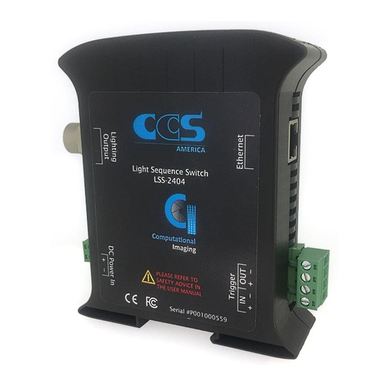
LSS-2404 B. Mechanical Drawing Ethernet Jack Trigger I/O Status Indicator DIN Rail Lock Lighting Output Connector Power ø15 Input Model name LSS-2404 Output channels Input voltage 10.8-28.8 VDC Power consumption 5W Max 136 g Weight Scale 2:3 Units: mm 35 |... -
Page 40: Timing Diagrams For Triggering
LSS-2404 C. Timing Diagrams for Triggering Trigger Type: One Shot (Default) Trigger Event: Series When a trigger is sent in, the first recipe runs until completion then waits until it receives another trigger to trigger the recipe again. When a recipe is triggered it runs all sequences; the frames within a sequence and the number of times a sequence is programmed to execute. - Page 41 LSS-2404 Trigger Event: Sequence Every trigger that comes in triggers the next sequence in the recipe. When a sequence is triggered it runs through all programmed frames then stops and waits for another trigger to start the next sequence. If the sequence is programmed to execute multiple times; one trigger will run all the executions for that sequence.
- Page 42 LSS-2404 Trigger Event: Frame Every trigger that comes in triggers the next frame in the sequence. The first trigger enables the recipe, first sequence, and first frame. The next trigger triggers the second frame in the same sequence and so on until all the frames have been triggered.
- Page 43 LSS-2404 Trigger Type: Continuous Recipe runs in a loop as long as the trigger signal remains high. When the trigger signal drops the LSS finishes the recipe that has started and ends. Trigger Type: Free-Run Recipe runs in a loop as long as the free-run trigger type is enabled. It does not require a trigger to begin running the sequence.
-
Page 44: Connection Diagram
LSS-2404 D. Connection Diagram LSS Master See below for specific instructions for NPN, PNP, opto-isolator, and open collector. Camera/Device 40 | P a g e... - Page 45 LSS-2404 Trigger-In Connection NPN/Open Collector To connect with an NPN signal wire as shown below and be sure to check the ‘Ground Trigger’ button in the GUI. To connect with a PNP signal; wire as shown below and leave the ground trigger button unchecked in the GUI.
- Page 46 LSS-2404 Opto-Isolator (NPN) To connect with an NPN opto-isolator signal wire as shown below and be sure to check the ‘Ground Trigger’ button in the GUI. Trigger-Out Connection The trigger-out of LSS is voltage output. Be sure to set the output voltage level (in the GUI) to match the camera’s or external trigger device’s trigger voltage.
- Page 47 LSS-2404 LSS Slave To use the camera as the master and the LSS as the slave the ‘Trigger Type’ must be set to ‘One-shot’ and the ‘Trigger Event’ must be set to ‘Frame’. See below for camera wiring for most NPN, PNP, opto-isolator, and open connector.
- Page 48 LSS-2404 Trigger-In Connection NPN/Open Connector To connect with an NPN signal wire as shown below and be sure to check the ‘Ground Trigger’ button in the GUI. To connect with a PNP signal wire the system as shown below. In the GUI; leave the ground trigger button unchecked and be sure to adjust the ‘Trigger Voltage’...
- Page 49 LSS-2404 Opto-Isolator Be sure to check the ground trigger button in the GUI. 45 | P a g e...
-
Page 50: Api Commands
LSS-2404 E. API Commands HTTP RESTful APIs APIs follow general rule of '=' indicates set and no '=' indicates get. The exception is when a get API requires a value. Set APIs generally return xxx=PASS or xxx=FAIL. Get APIs return either a single value or a JSON object. - Page 51 LSS-2404 /frameGet= Returns JSON formatted Frame in active Recipe of given name. /sequenceGet= Returns JSON formatted Sequence in active Recipe of given name. /seriesGet= Returns JSON formatted Series in active Recipe of given name. /configGet= Returns JSON formatted Config in active Recipe of given name.
- Page 52 LSS-2404 /recipeValid= Returns PASS if Recipe stored in non-volatile memory at given Recipe number (1-6) is valid. /recipeSave= Saves active Recipe to non-volatile memory at given Recipe number (1-6). Settings /statusColorSet= Sets Status LED indicator color mapping (JSON format). "status": status (see below and in user manual) "red":...
- Page 53 LSS-2404 /statusLevel Returns Status LED indicator brightness 1-100%. /status= Sets status (see /statusColorSet= API for definition of status). /status Returns status (see /statusColorSet= API for definition of status). /triggerStrobe= Sets Status LED indicator Trigger Strobe duration in milliseconds. /triggerStrobe Returns Status LED indicator Trigger Strobe duration in milliseconds.
- Page 54 LSS-2404 Diagnostics /ch1= ... /ch12= Sets channel output (0=off, 1=on). /ch= Sets all channel outputs (bitmapped hex format - D0=ch1 ... D11=ch12). /triggerOut1= /triggerOut2= Sets Trigger Output (0=off, 1=on). /Vtrigger= Sets Trigger Output voltage (5,12, or 24). /triggerIn1 /triggerIn2 Returns Trigger Input ADC voltage reading in float format (scaled by 1/9.069 of voltage at Trigger Input connector pin).
- Page 55 LSS-2404 /sncm Returns CM serial number (string format 64 characters max). /snCCS= Sets CCS America serial number (string format 64 characters max). /snCCS Returns CCS America serial number (string format 64 characters max). JSON Object Format Examples All JSON objects are fixed size and must contain all parameters.
- Page 56 LSS-2404 "channels": 0,200000, // channel 1 start/end time 0,0, // channel 2 start/end time 0,0, 0,0, 0,0, 0,0, 0,0, 0,0, 0,0, 0,0, 0,0, // channel 12 start/end time Sequence sequence= "type" :"sequence",// obj type - sequence "name" :"Seq1", // sequence name "framingModeFlag"...
- Page 57 LSS-2404 "FrSeq1Fr4", "0","0","0","0","0","0","0","0","0","0" // blank must // be "0" "repeats": // list of repeats for each frame 0,0,0,0,0,0,0,0,0,0 Series series= "type" :"series", // object type - series "name" :"Ser1", // series name "sequenceNames" : // list of 10 sequence names "Seq1",...
- Page 58 LSS-2404 Config config= "type" :"config", // object type - config "name" :"Cfg1", // config name "version" // Recipe version "triggerInputs": "level" :0.15,// 0.0 - 24.0 volts "polarityHighFlag" // 1=high, 0=low "type" // 1=oneShot // 2=activeRun // 3=freeRun "groundTriggerFlag" // 1=ground trigger "delay"...
- Page 59 LSS-2404 "groundTriggerFlag" "delay" "event" "function" "triggerOutputs": "level" :5, // 5,12,24 volts "polarityHighFlag":0,// 1=high, 0=low "width" :100 // global width "level" "polarityHighFlag":0, "width" :100 "resolutionUSFlag" :0, // 0=ms, 1=us (GUI only) "outputDelay" // output delay from camera 55 | P a g e...
- Page 60 LSS-2404 Use Case: Storing a Recipe to the LSS The following API stopping/disabling current Recipe and loads/enables a new Recipe: /stop stop current Recipe /trigInDisable prevent trigger of current Recipe /config={...} send Config (MUST before Frame/Sequence/Series) /frame={...} send Frames (MUST bebefore Sequences/Series) /sequence={...} send Sequences (MUST be before Series)
-
Page 61: Multi Shot Imaging Examples
LSS-2404 F. Multi Shot Imaging Examples Example 1 How to set up a program that has: one PMS image, 3 normal ring light images, and one image that only illuminates the left quadrant of the light (lighting block 2). During execution only one trigger is needed to run the entire recipe. - Page 62 LSS-2404 Sequence 2: The next images require a longer strobe width to create a brighter image. The frame time and strobe width have been increased. The capture time is 30 ms. Sequence 3: The frame time and strobe width are increased. The capture time is 30 ms.
- Page 63 LSS-2404 This page is left blank for your notes: 59 | P a g e...
- Page 64 LSS-2404 Issue 2.0E – July 2018 © Copyright 2017 CCS America, Inc. CCS America, Inc. CCS Japan Inc. 6 Lincoln Knoll Lane 374 Okakuencho, Shimodachiuri-agura, Suite 102 Karasuma-dori, Kamigyo-ku Burlington, MA 01803 Kyoto, 602-8011, Japan T: 781-272-6900 T: +81-75-415-8277 F: 781-272-6902 F: +81-75-415-8278 www.ccsamerica.com...
Need help?
Do you have a question about the LSS-2404 and is the answer not in the manual?
Questions and answers