Table of Contents
Advertisement
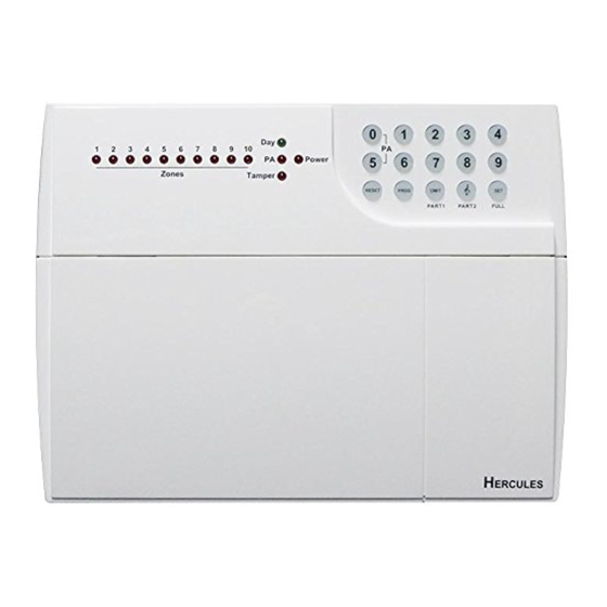
10 Zone LED Alarm Panel - Engineering Manual
Hercules 10 Zone onboard LED Alarm Panel
Engineering Manual
SAFETY
Before proceeding with the installation, please note the following safety warnings:
DO NOT connect the mains supply directly to the product, this will cause permanent damage to the products.
Control panel is for indoor use only. Avoid mounting location which can expose this product to splashing or dripping
liquid.
Always follow the manufacturer's advice when using any tools power tools, ladder/steps,. using steps or ladders, and
wear suitable protective equipment (e.g. safety goggles) when drilling holes, etc. The use of ear defenders are advisable
when working in close proximity to the External Siren or the Control Panel's Siren when the front panel cover is
removed due to the high sound level produced by it. Before drilling holes in walls, check for hidden electricity cables
and water pipes. The use of a cable/pipe locator is advisable if in doubt. Batteries (battery pack or batteries installed)
should not be exposed to excessive heat. Danger of damage to the unit may occur if battery is incorrectly replaced.
Replace only with the same or equivalent type. (Do not mix batteries type).
1
Advertisement
Table of Contents

Summary of Contents for Hercules 10
- Page 1 10 Zone LED Alarm Panel - Engineering Manual Hercules 10 Zone onboard LED Alarm Panel Engineering Manual SAFETY Before proceeding with the installation, please note the following safety warnings: DO NOT connect the mains supply directly to the product, this will cause permanent damage to the products.
-
Page 2: Table Of Contents
2.6 - Fire Zone Circuit........................10 2.7 - Tamper Zone Circuit......................11 2.8 - PA Zone Circuit ........................11 2.9 - Extension speaker ........................11 2.10 - External siren Output (Bell box) ..................12 2.10.1 - Vortex Ⅱ w iring to control panel ..................13 2.10.2 - Solar bell wiring to control panel.................. - Page 3 10 Zone LED Alarm Panel - Engineering Manual SECTION 5 - FIRST POWER UP ..................18 SECTION 6 – HOW TO SET UP THE SYSTEM ..............20 6.1 - How to enter Engineer Program Mode................20 6.2 - Setup Programs........................21 6.2.1 - How to go into Full mode Setting..................21 6.2.2 - How to go into Part 1 mode Setting..................
- Page 4 10 Zone LED Alarm Panel - Engineering Manual 7.5 - How to use Panic Alarm on keypad ..................40 SECTION 8 - MAINTENANCE ..................41 SECTION 9 - TROUBLESHOOTING GUIDE..............41 SECTION 10 - SPECIFICATIONS ...................43 APPENDIX 1 – ZONE - LOCATION TABLE ..............44 DISPOSAL AND RECYCLING..................44...
-
Page 5: Section 1 - Overview Of System
10 Zone LED Alarm Panel - Engineering Manual Section 1 - Overview of System The 10 zone intruder alarm system is an indoor alarm system based on advanced technology to give professional levels of protection and reliability. It is 10 zone wired system with special electronic design for short-circuit protection. -
Page 6: Tools Required
Ladder or other safe working platform • 1.3 - System Feature 10 Zones programmable for Security, PA, Fire, 24Hr Tamper TAMPER input Output for External Bell Box and Strobe 4 Access Level Codes, manager code, engineer code, user code (2 user codes), holiday code, all programmable. -
Page 7: Section 2 - Installing Your System
10 Zone LED Alarm Panel - Engineering Manual Section 2 – Installing your System In choosing a suitable location you should bear in mind: The need to reach the CU easily, within the 30 seconds, when entering and leaving the premises, ideally passing only one detector. -
Page 8: Pcb
10 Zone LED Alarm Panel - Engineering Manual 2.2 - PCB There are three fuses mounted on the circuit board. All are 20mm anti-surge 1.6A – to protect the positive (+Ve) line of 12V battery 1A – to protect the RKP 13V supply 1A –... -
Page 9: Remote Keypads
10 Zone LED Alarm Panel - Engineering Manual 2.4 - Remote Keypads 1). Select LED remote keypad jumper To set the address of the Remote Keypads, please apply the jumper links as follows, Keypad 1 Keypad 2 Keypad 3 Keypad 4... -
Page 10: Security Zones
10 Zone LED Alarm Panel - Engineering Manual Fitting the Remote Keypad a. Separate the RKP base plate from the main assembly by slackening the retaining screw. b. Cut away the required thin wall sections around the edges of the base plate for cable entry. -
Page 11: Tamper Zone Circuit
10 Zone LED Alarm Panel - Engineering Manual 2.7 - Tamper Zone Circuit Any zone may be programmed as a Tamper zone. Operational in Day and set, the Tamper circuit will cause a full alarm condition when activated. 2.8 - PA Zone Circuit... -
Page 12: External Siren Output (Bell Box)
10 Zone LED Alarm Panel - Engineering Manual Only one 16 ohms extension speaker may be wired across the speaker terminals. Mounted in convenient positions within the installation the extension speakers will reproduce all of the alarm tones generated by the control panel. -
Page 13: Vortex Ii
10 Zone LED Alarm Panel - Engineering Manual 2.10.1 - VortexⅡ Ⅱ Ⅱ Ⅱ wiring to control panel Vortex II wiring to control panel HOLD OFF Board VORTEX II... -
Page 14: Solar Bell Wiring To Control Panel
10 Zone LED Alarm Panel - Engineering Manual 2.10.2 - Solar bell wiring to control panel Solar bell wiring to control panel +12V Board Solar bell... -
Page 15: Ad2510 Wiring To Control Panel
10 Zone LED Alarm Panel - Engineering Manual 2.10.3 - AD2510 wiring to control panel AD2510 wiring to control panel 2.11 - 13V Supply Output The 13V output is to power detectors which require a voltage supply (PIR detector etc). The supply is present at all times and may be used to supply a total of 350mA. -
Page 16: Section 3 - Factory Default Setting
10 Zone LED Alarm Panel - Engineering Manual Section 3 - Factory Default Setting System status System flag SET mode User code 1-2 : Not used Silent PA : Off Full mode: Holiday code : Not used RKP PA : On... -
Page 17: Section 4 - Mains Connection
10 Zone LED Alarm Panel - Engineering Manual Section 4 - Mains Connection The mains power should be connected using a 3 core cable of not less than 1mm sq. from a fused spur to the mains connector inside the control panel. -
Page 18: Section 5 - First Power Up
Fit the battery wires to the BATT terminals on the Board, Red to +and Black to -. c. On connecting the battery the system will now go into alarm condition and Day led is indication. 1 2 3 4 5 6 7 8 9 10 TAMP Alarm sound d. - Page 19 Press to return to Day mode. R E S T 1 2 3 4 5 6 7 8 9 10 TAMP g. Immediately enter the engineer code 9-9-9-9 factory default setting. Or go to page 16 how to enter program mode. If authorized by manager code.
-
Page 20: Section 6 - How To Set Up The System
You should require the manager to authorize Engineer access. It is accessed directly form Day mode via the Engineer code. To operate the “Enter Engineer operation mode” as follow: · E nter Manager program mode. 1 2 3 4 5 6 7 8 9 10 · P ress TAMP · P ress to authorize Engineer access. -
Page 21: Setup Programs
Zones can also be assigned different functions in different programs. Refer to the following diagram for the programming structure. 6.2.1 - How to go into Full mode Setting · U nder Engineer mode. 1 2 3 4 5 6 7 8 9 10 to Select Setup Programs. · P ress TAMP to accept and go into Program Full. -
Page 22: How To Set Zone Function
Set zone Immediate function Under Engineer Menu/Setup Program, the program 1 2 3 4 5 6 7 8 9 10 Full mode is chosen. LED 1 and LED 2 is flashing. TAMP ·... - Page 23 10 Zone LED Alarm Panel - Engineering Manual Set zone Timed function 1 2 3 4 5 6 7 8 9 10 Under Engineer Menu/Setup Program, the program Full mode is chosen. LED 1 and LED 2 is flashing. TAMP ·...
-
Page 24: How To Set Exit Mode Function
A disabled program is not available for use and cannot be selected and setting time. Under Engineer Menu/Setup Program, the program 1 2 3 4 5 6 7 8 9 10 Full mode is chosen. LED 1 and LED 2 are flashing. -
Page 25: How To Set Exit Time Function
This is the time allowed to leave the premises via the exit route before the system sets. The programmable range is 00-99 seconds. If the Exit Time is interrupted with the last 10 seconds, then the Exit Time will restart at 10 seconds after the interruption has cleared. -
Page 26: Setup Zones Type
A zone may be programmed as Not used, and then is ignored by the panel. To operate the Setup Zone type as follow. 1 2 3 4 5 6 7 8 9 10 e.g. Change zone 5 type to Tamper/24Hr. -
Page 27: Setup Zones Attrs
Note: The zone must to be set to security then it can be set omit allowed. Double Knock: Double knock programming is used when zones are likely to create false activations. Double knock requires two activations within 10 minutes of the same Zone or a Zone left open for 10 seconds. Chime: If a Security Zone is programmed as Chime, you can hear special tone when it is triggered in DAY mode. -
Page 28: Setup Codes
10 Zone LED Alarm Panel - Engineering Manual · P ress to accept the change E S T 1 2 3 4 5 6 7 8 9 10 or press to cancel. R E S T TAMP Chime · U nder Engineer mode 1 2 3 4 5 6 7 8 9 10 ·... -
Page 29: How To Set Up/Change User Code
10 Zone LED Alarm Panel - Engineering Manual 6.5.1 - How to set up/change User Code Under Engineer Menu. 1 2 3 4 5 6 7 8 9 10 · P ress to select Setup User codes. TAMP · P ress to change User 1. -
Page 30: Setup System
10 Zone LED Alarm Panel - Engineering Manual 6.6 - Setup system The Setup system contains five parts. They are listed as follow: 1 = Flags1, 2 = Flags2, 3 = Bell Time, 4 = Rearm count, 5 = Bell delay time 6.6.1 - How to Setup System Flags... - Page 31 10 Zone LED Alarm Panel - Engineering Manual · U nder Engineer mode 1 2 3 4 5 6 7 8 9 10 · P ress to select Setup system. TAMP · P ress to select system flag item. 1 2 3 4 5 6 7 8 9 10 TAMP ·...
- Page 32 Zone wiring, as shown in the following diagram. Note the PIR detectors usually have a “spare” terminal for this purpose. To operate Flag 2 as follow. · U nder Engineer mode. 1 2 3 4 5 6 7 8 9 10 · P ress to select Setup system. TAMP ·...
-
Page 33: How To Setup Bell Time
This is the duration that the external bell output is active. The range is 01-20 minutes. The default is 14 minutes. e.g. Change the Bell Time from 14 to 15 minutes. · U nder Engineer mode 1 2 3 4 5 6 7 8 9 10 · P ress to select Setup system. TAMP 1 2 3 4 5 6 7 8 9 10 ·... -
Page 34: How To Setup Bell Delay Time
10 Zone LED Alarm Panel - Engineering Manual 6.6.4 - How to Setup Bell delay time This delays the activation of the Bell for the required time. The range is 00-10 minutes. The default is 00 minutes. Change the Bell Delay time from 0 to 1 minute. -
Page 35: How To Restore To Factory Value Using Menu
CAUTION: All configurations of the panel are reset to reset to factory default conditions. To default to factory settings: · · · · U nder Engineer mode to top of menu. 1 2 3 4 5 6 7 8 9 10 LED 1~10 is flashing. TAMP · P ress O I MT twice within 2 second. -
Page 36: Test System
The test outputs are: 0 = BELL, 1 = Strobe, 2 = Speaker, · U nder Engineer code · P ress key to Select Test System. 1 2 3 4 5 6 7 8 9 10 TAMP · P ress key to select Bell test. -
Page 37: How To Enter Walk Test
A tone is generated as each zone or tamper is activated (opened). e.g. Trigger Zone and Zone tamper · U nder Engineer code 1 2 3 4 5 6 7 8 9 10 · P ress key to Select Test System. -
Page 38: Section 7 - Using System
Full Mode, Part1 Mode and Part2 mode. You can set them as follows. · S ystem is in Day mode and has power. 1 2 3 4 5 6 7 8 9 10 TAMP · E nter User code/Manager code... -
Page 39: How To Omit A Zone(S)
4, corresponding is LED OFF. 1 2 3 4 5 6 7 8 9 10 Press same key to toggle ON/OFF. Note: 1-9 key= zone1 –zone 9, 0 key = zone 10. TAMP E S T · P ress... -
Page 40: How To Unset From Alarm And Reset The System
See Engineer mode / Setup System/ Flags 1. e.g. Control Panel tamper trigger alarm · S ystem is in Set mode. 1 2 3 4 5 6 7 8 9 10 TAMP · E nter User code/Manager code... -
Page 41: Section 8 - Maintenance
10 Zone LED Alarm Panel - Engineering Manual Section 8 - Maintenance Once every three months, Test all detectors. • Check loudspeaker of control unit. • Test sirens and strobes of the bellbox. • Additionally, once every year, Check external bell box •... - Page 42 R E S T Mains Fail · S ystem is in Day mode. 1 2 3 4 5 6 7 8 9 10 Day LED ON, TAMP LED flashing. TAMP · E nter User code / Manager code Show Z1 LED flashing.
-
Page 43: Section 10 - Specifications
10 Zone LED Alarm Panel - Engineering Manual Section 10 - Specifications 10 ZONE ONBOARD LED ALARM PANEL Type of Alarm Panel Microprocessor based control unit Housing Entry Delay default 45 seconds, programmable Exit Delay default 45 seconds, programmable Alarm Zone... -
Page 44: Appendix 1 - Zone - Location Table
10 Zone LED Alarm Panel - Engineering Manual Appendix 1 – Zone - Location Table Zone Number Location Disposal and Recycling Batteries and waste electrical products should not be disposed of with household waste. Please recycle where these facilities exist.
Need help?
Do you have a question about the 10 and is the answer not in the manual?
Questions and answers