Advertisement
OWNER'S MANUAL
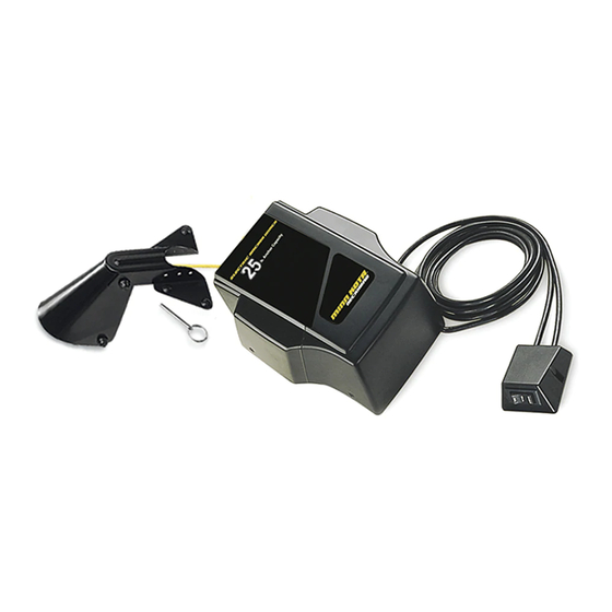
DeckHand
™
Model:
DH 25R
NOTE: Numbers in ( ) are item numbers referring to parts diagram.
A. Winch and Davit mounted together
1. Remove DeckHand cover (1) by removing cover screws, items (3) and (4).
2. Place the base (18) and the davit (53) in your desired mounting location. Make sure that when
the DeckHand is operating or in a stowed position, the anchor does not come in contact with the
boat.
3. Make sure there are no obstructions under the mounting surface prior to drilling. Mark at
least 4 of the 6 pre-drilled bolt hole location provided in your base for drilling. Also mark all 4 pre-
drilled bolt hole locations provided in your davit for drilling. Drill through the marked holes in the
base using a 21 /64" drill bit, and through the marked holes in the davit using 17 /64" drill bit.
winch assembly
treuil
davit assembly
bossoir
cover
base
bolt
3"
75 mm
flat washer
rubber washer
rondelle plate
nut
Advertisement
Table of Contents

Related Manuals for MINN KOTA DeckHand DH 25R

Summary of Contents for MINN KOTA DeckHand DH 25R
- Page 1 NOTE: Numbers in ( ) are item numbers referring to parts diagram. A. Winch and Davit mounted together 1. Remove DeckHand cover (1) by removing cover screws, items (3) and (4). DeckHand ™ 2. Place the base (18) and the davit (53) in your desired mounting location. Make sure that when the DeckHand is operating or in a stowed position, the anchor does not come in contact with the boat.
-
Page 2: Switch Installation
Item Part Description SWITCH INSTALLATION 2370209 Cover DH-25R 2303005 Pig Ring Your DeckHand control switch assembly (39) is equipped with an eighteen foot control wire, 2372121 Screw-#8-18x 1-1/2 Stallgrd (2 .ea) allowing convenient mounting almost anywhere in the boat. 2372111 Screw-#8-18x3/4 Stallgrd (2 .ea) Select a control switch mounting location. -
Page 3: Function Test
ROPE REPLACEMENT AND INSTALLATION Spool and rope assemblies may be pur- chased direct from Minn Kota or autho- rized Minn Kota Service Centers. Should you decide to replace your own rope, it is recommended to use a 3/16” diameter diamond braid polyester or nylon rope. -
Page 4: Battery Connections
BATTERY CONNECTIONS CAUTION: Center control switch in “Off” posi- • Improper polarity hook-up of battery tion. leadwire could cause severe damage Connect DeckHand leadwire to to gear motor. 12V battery. If additional leadwire • The DeckHand is provided with a length is needed, use a minimum sealed control switch and manual of 10 gauge wire. -
Page 5: Maintenance
MAINTENANCE CONTROL SWITCH OPERATIONS • After use, rinse unit in fresh water and wipe down unit with a damp cloth.This unit is not intended for saltwater use. Saltwater use will void your warranty. WARNING: Keep fingers clear of rope and base when •...
Need help?
Do you have a question about the DeckHand DH 25R and is the answer not in the manual?
Questions and answers