Table of Contents
Advertisement
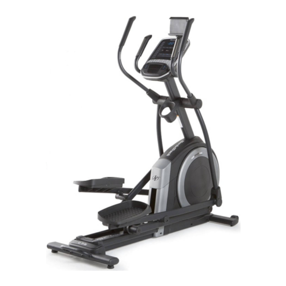
Model No. NTEVEL89818.0
Serial No.
Write the serial number in the space
above for reference.
Serial Number
Decal
CUSTOMER SERVICE
UNITED KINGDOM
Call: 0330 123 1045
From Ireland: 053 92 36102
Website: iconsupport.eu
E-mail: csuk@iconeurope.com
Write:
ICON Health & Fitness, Ltd.
Unit 4, Westgate Court
Silkwood Park
OSSETT
WF5 9TT
UNITED KINGDOM
AUSTRALIA
Call: 1800 993 770
E-mail: australiacc@iconfitness.com
Write:
ICON Health & Fitness
PO Box 635
WINSTON HILLS NSW 2153
AUSTRALIA
CAUTION
Read all precautions and
instructions in this manual before
using this equipment. Keep this
manual for future reference.
USER'S MANUAL
iconeurope.com
Advertisement
Table of Contents

Related Manuals for NordicTrack C 7.5


Summary of Contents for NordicTrack C 7.5
- Page 1 Model No. NTEVEL89818.0 Serial No. USER’S MANUAL Write the serial number in the space above for reference. Serial Number Decal CUSTOMER SERVICE UNITED KINGDOM Call: 0330 123 1045 From Ireland: 053 92 36102 Website: iconsupport.eu E-mail: csuk@iconeurope.com Write: ICON Health & Fitness, Ltd. Unit 4, Westgate Court Silkwood Park OSSETT...
-
Page 2: Table Of Contents
NORDICTRACK and IFIT are registered trademarks of ICON Health & Fitness, Inc. App Store is a trademark of Apple Inc., registered in the U.S. and other countries. Android and Google Play are trademarks of Google LLC. -
Page 3: Important Precautions
IMPORTANT PRECAUTIONS WARNING: To reduce the risk of burns, fire, electric shock, or injury to persons, read all important precautions and instructions in this manual and all warnings on your elliptical before using your elliptical. ICON assumes no responsibility for personal injury or property damage sus- tained by or through the use of this product. - Page 4 18. The elliptical does not have a freewheel; the 20. Over exercising may result in serious injury pedals will continue to move until the fly- or death. If you feel faint, if you become short wheel stops. Reduce your pedaling speed in of breath, or if you experience pain while a controlled way.
-
Page 5: Before You Begin
Thank you for selecting the revolutionary reading this manual, please see the front cover of this NORDICTRACK C 7.5 elliptical. The C 7.5 elliptical manual. To help us assist you, note the product model ® provides an impressive selection of features designed number and serial number before contacting us. -
Page 6: Part Identification Chart
PART IDENTIFICATION CHART Use the drawings below to identify the small parts needed for assembly. The number in parentheses below each drawing is the key number of the part, from the PART LIST near the end of this manual. The number following the key number is the quantity needed for assembly. -
Page 7: Assembly
ASSEMBLY • Assembly requires two persons. • In addition to the included tool(s), assembly requires the following tools: • Place all parts in a cleared area and remove the one Phillips screwdriver packing materials. Do not dispose of the packing materials until you finish all assembly steps. - Page 8 2. With the help of a second person, place some of the packing materials (not shown) under the rear of the Frame (1). Have the second person hold the Frame to prevent it from tipping while you complete this step. If there are shipping supports attached to the rear of the Frame (1), remove the screws from the shipping supports, and discard the screws...
- Page 9 4. Using a plastic bag to keep your fingers clean, apply some of the included grease to the right Crank Arm (20). Next, identify the Right Roller Arm (59), orient it as shown, and slide it onto the right Crank Arm (20).
- Page 10 6. Locate the wire tie (A) in the lower end of the Upright (4). Tie the wire tie to the Upper Wire (110) as shown in the inset drawing. Then, pull the upper end of the wire tie until the Upper Wire is routed through the Upright.
- Page 11 8. Orient the Right Pedal Arm (58) as shown, and then apply grease to the axle. Insert the Right Pedal Arm (58) into the Right Upper Body Leg (60) and into the Right Roller Arm (59). Attach the Right Pedal Arm (58) to the Right Roller Arm (59) with an M8 x 20mm Flat Head Screw (120) and a Retainer (55);...
- Page 12 10. See step 5. Tighten the four M10 x 25mm Screws (92). Next, untie and discard the wire tie on the Upper Avoid pinching Wire (110). the wires While a second person holds the Console (7) near the Upright (4), plug the Upper Wire (110) and the Pulse Wire (63) into the receptacles on the Console.
- Page 13 12. Orient the Accessory Tray (37) as shown, and attach it to the Upright (4) with two M4 x 16mm Screws (101). 13. Orient a Lower Tray Cover (81) as shown, and attach it to the right side of the Accessory Tray (37) with two M4 x 16mm Screws (101).
- Page 14 15. Orient the Front Shield Cover (117) and the Center Shield Cover (75) around the Upright (4). Then, attach them to each other with two M4 x 16mm Screws (101). Avoid pinching the wires Tip: Avoid pinching the wires. Press the Front Shield Cover (117) and the Center Shield Cover 73, 74 (75) into the Left and Right Shields (73, 74).
- Page 15 18. Attach the Tablet Holder (132) to the Console (7) with four Tablet Holder Screws (133); start all the Tablet Holder Screws, and then tighten them. 19. Make sure that all parts are properly tightened. Place a mat beneath the elliptical to protect the floor. Extra parts may be included.
-
Page 16: How To Use The Elliptical
HOW TO USE THE ELLIPTICAL HOW TO PLUG IN THE POWER CORD Follow the steps below to plug in the power cord. This product must be earthed. If it should 1. Plug the indicated end of the power cord into the malfunction or break down, earthing provides a path of socket on the frame. - Page 17 HOW TO MOVE THE ELLIPTICAL HOW TO LEVEL THE ELLIPTICAL Due to the size and weight of the elliptical, moving If the elliptical rocks slightly on your floor during use, it requires two persons. Stand in front of the elliptical, turn one or both of the leveling feet (D) beneath the hold the upright (A), and place one foot against one of rear of the frame or turn the leveling foot (E) under...
- Page 18 HOW TO EXERCISE ON THE ELLIPTICAL To mount the elliptical, hold the handlebars (G) or the upper body arms (H) and step onto the pedal (I) that is in the lower position. Then, step onto the other pedal. Push the pedals until they begin to move with a con- tinuous motion.
- Page 19 CONSOLE DIAGRAM FEATURES OF THE CONSOLE a target pedaling speed as it guides you through an effective workout. The advanced console offers an array of features designed to make your workouts more effective and You can even listen to your favorite workout music or enjoyable.
- Page 20 HOW TO TURN ON THE POWER 2. Select the manual mode. IMPORTANT: If the elliptical has been exposed to When you turn on the console, the manual mode cold temperatures, allow it to warm to room tem- will be selected automatically. perature before you turn on the power.
- Page 21 Calories per Hour (CALS/HR)—The approximate To manually advance the scan cycle, press the number of calories you are burning per hour. Multi-scan button repeatedly. Resistance (RESIST)—The resistance level of the To turn off the scan mode, press the Next Display pedals.
- Page 22 5. Measure your heart rate if desired. If the display does not show your heart rate, make sure that your hands are positioned as described. You can measure your heart rate using either Be careful not to move your hands excessively or the handgrip heart rate monitor or an optional to squeeze the contacts tightly.
- Page 23 HOW TO USE AN ONBOARD WORKOUT decrease your pedaling speed. When no words appear, maintain your current pedaling speed. 1. Begin pedaling or press any button on the console to turn on the console. See HOW TO TURN ON THE POWER on page 20.
- Page 24 HOW TO USE THE SOUND SYSTEM HOW TO CONNECT YOUR TABLET TO THE CONSOLE To play music or audio books through the console sound system while you exercise, plug a 3.5 mm male The console supports BLUETOOTH connections to 3.5 mm male audio cable (not included) into the to tablets via the iFit–Smart Cardio Equipment app jack on the console and into a jack on your personal and to compatible heart rate monitors.
- Page 25 5. Disconnect your tablet from the console if HOW TO CHANGE CONSOLE SETTINGS desired. 1. Select the settings mode. To disconnect your tablet from the console, first select the disconnect option in the iFit–Smart If you are using the manual mode or an onboard Cardio Equipment app.
- Page 26 Display Test—This screen is intended to be used Contrast Level—The currently selected contrast by service technicians to identify whether the level will appear in the display. Press the display is working correctly. Resistance increase and decrease buttons to adjust the contrast level. Button Test—This screen is intended to be used by service technicians to identify whether a certain button is working correctly.
-
Page 27: Maintenance And Troubleshooting
MAINTENANCE AND TROUBLESHOOTING MAINTENANCE If lines appear in the console display, see step 3 on page 25 and adjust the contrast level of the display. Regular maintenance is important for optimal performance and to reduce wear. Inspect and properly If the ramp does not adjust to the selected incline level, tighten all parts each time the elliptical is used. - Page 28 HOW TO ADJUST THE REED SWITCH Next, slightly loosen the indicated two M4 x 12mm Self-tapping Screws (50). Slide the Reed Switch (38) If the console does not display correct feedback, the slightly closer to or away from the Magnet (43), and reed switch should be adjusted.
- Page 29 HOW TO ADJUST THE DRIVE BELT Next, locate and loosen the If the pedals slip while you are pedaling, even while Idler Screw (89). the resistance is adjusted to the highest level, the drive Tighten the Drive belt may need to be adjusted. To adjust the drive belt, Belt Adjustment first press the power switch and unplug the power Screw (91) until...
-
Page 30: Exercise Guidelines
EXERCISE GUIDELINES Burning Fat—To burn fat effectively, you must exer- WARNING: cise at a low intensity level for a sustained period of Before beginning this time. During the first few minutes of exercise, your or any exercise program, consult your physi- body uses carbohydrate calories for energy. -
Page 31: Part List
PART LIST Model No. NTEVEL89818.0 R0918A Key No. Qty. Description Key No. Qty. Description Frame/Ramp Roller Rear Stabilizer Left Pedal Handle Access Cover Axle Cover Upright Pivot Spacer M4 x 19mm Screw Retainer Front Stabilizer Roller Arm Bushing Console Large Arm Bearing Roller Guide Right Pedal Arm Crank Bearing Spacer... - Page 32 Key No. Qty. Description Key No. Qty. Description M4 x 16mm Screw Frame Bushing M8 Locknut M10 x 47mm Bolt M6 x 12mm Screw Small Arm Bearing M10 x 115mm Screw M4 x 16mm Machine Screw M4 x 25mm Flange Screw Right Upper Grip Lower Ramp Cover M4 x 25mm Screw...
-
Page 33: Exploded Drawing
EXPLODED DRAWING A Model No. NTEVEL89818.0 R0918A... - Page 34 EXPLODED DRAWING B Model No. NTEVEL89818.0 R0918A...
- Page 35 EXPLODED DRAWING C Model No. NTEVEL89818.0 R0918A...
-
Page 36: Ordering Replacement Parts
ORDERING REPLACEMENT PARTS To order replacement parts, please see the front cover of this manual. To help us assist you, be prepared to provide the following information when contacting us: • the model number and serial number of the product (see the front cover of this manual) •...
Need help?
Do you have a question about the C 7.5 and is the answer not in the manual?
Questions and answers