Table of Contents
Advertisement
Advertisement
Table of Contents

Related Manuals for Baur TG 20/50


Summary of Contents for Baur TG 20/50
- Page 1 User Manual Audio Frequency System Locator-Set TG 20/50, TG 600 UL 30 Ref. No. 822-119 11/2005 BAUR Prüf- und Messtechnik GmbH e-mail: headoffice@baur.at Tel. +43/5522/4941-0 Raiffeisenstrasse 8, A-6832 Sulz/Austria internet: www.baur.at Fax +43/5522/4941-3...
- Page 3 BAUR. Important information about the instrument! In any case, read carefully! Important information text. © BAUR Prüf- und Messtechnik GmbH, A-6832- Copyright Sulz / Austria All rights reserved. No part of this publication may be reproduced,...
- Page 4 The warranty does not cover damage in transit, batteries, fuses readjustments accordance with the Operating Instructions! We draw attention in addition to the ‘General Sales and Business Conditions’ of: BAUR Prüf- und Messtechnik GmbH Raiffeisenstrasse 8 A-6832-Sulz / Austria...
-
Page 5: Table Of Contents
Contents Product information Description of Locator-Set Audio Frequency Generator TG 20/50 and TG 600 2.1.1 TG 20/50 2.1.2 TG 600 Universal Locator UL 30 2.2.1 Menu Magnetic and acoustic sensors Technical data Put TG 20/50 into operation Put TG 600 into operation... -
Page 6: Product Information
1 Product information In combination with Surge Voltage Generators (SSG / STG) or Audio Frequency Generators (TG20/50 and TG600) and accessories like BM 30, earth sticks, the Universallocator UL 30 is used for: pin-pointing of cable faults route tracing of buried cables or metallic pipes propagation time measurement Cable sheath fault location Combined tracing and pin pointing... -
Page 7: Description Of Locator-Set
Cable detection even on live cables and lines Location of cable joints and branches Accurate pin-point fault location according to the BAUR twist method in conjunction with the powerful Audio Frequency Transmitter TG20/50 or TG600. Accurate pin-point fault location in conjunction with the Surge Voltage Generator SSG. -
Page 8: Audio Frequency Generator Tg 20/50 And Tg 600
Audio Frequency Generator TG 20/50 and TG 600 Audio Frequency Generator TG 20/50 Description TG 20/50 The Audio Frequency Transmitter Locator TG 20/50 is a powerful, battery operated instrument with an integrated power supply unit. An output of 50 VA is available during mains operation and therefore application for accurate pin-point fault location on twisted multi-core cables is possible. -
Page 9: Tg 20/50
2.1.1 TG 20/50 Display elements: Power control Charge control Pointer instrument for I out and I in and battery control Indication of impedance level Operating elements: ON switch and mode selector Button for battery control and instrument illumination Button for indication of I in Button for switching measuring range x 0.1 for I out... -
Page 10: Tg 600
2.1.2 TG 600 18 17 16 4 4 6 8 10 2 3 14 1 5,7,9,11,20,19,12 13 Display elements: 1 Input current of adjusting transformer 2 Output current of adjusting transformer 3 Overtemperature indication Operating elements: 4 Mains ON 5 Mains OFF 6 Frequency selection 2 kHz 7 Frequency selection 10 kHz 8 Continuous operation... -
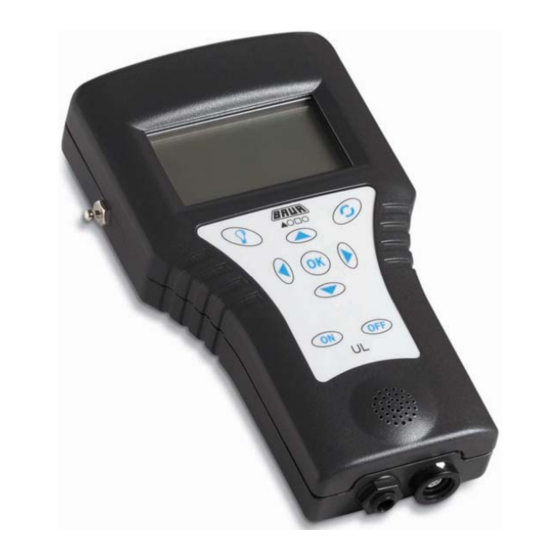
Page 11: Universal Locator Ul
Universal Locator UL 30 Input sockets for sheath fault sticks Display Up – for navigation or increase Backlight Switch button Left – for navigation or Right – for navigation decrease or increase Down – for navigation or increase ON / OFF button Loudspeaker Headphone outlet Socket for BM 30 / SP 30... -
Page 12: Menu
2.2.1 Menu A application-oriented menu structure allows fast and easy operation of the UL 30. At main menu the application could be selected. The following submenus contain the special fault location- respectively tracing methods. Fault location: Route tracing: Setup:... -
Page 13: Magnetic And Acoustic Sensors
Magnetic and acoustic sensors Several sensors are available for reception of magnetic and acoustic signals which are used depending on selected tracing and measuring method. BM 30 The highest sensitivity of the ground microphone is at the range of 200Hz. Therefore, it is most suitable for pin-pointing of flashover faults according to the Surge Voltage method. - Page 14 SP 30 The detecting rod consists of a searching coil adjusted to an oscillating circuit by condensers. Using the switch on the handle of the detecting rod the frequency can be adapted to the signal frequency of Audio Frequency Generator. hinged searching coil can be turned by 45°...
-
Page 15: Technical Data
Technical data Audio Frequency Generator TG20/50 Output power 0 - 50VA in mains operation 0- 20VA in battery operation Output current max. 8 A Output impedance in 7 steps 1 / 3 / 10 / 30 / 100 / 300 / 1000 W with automatic adaptation Frequencies 2 frequencies, switchable... - Page 16 Audio Frequency Generator TG 600 Output power at 2 kHz in 2 steps 600VA / 60VA at 10kHz in 2 steps 450VA / 45VA Output current max. 30 A Output impedance in 8 steps 0.3 / 0.8 / 1.8 / 4 / 10 / 30 / 100 / 300 W Frequencies Quarz-stabilized: 2kHz and 10kHz;...
- Page 17 Universal Locator UL 30 Receiving frequency 50Hz – 10kHz, 815Hz, 2kHz, 10kHz + 2 additional frequencies on request Filter digital Üassive reception 50/60Hz mains signal amplification 0-38 dB propagation velocity range 0-96ms operating temperature -20°C….+55°C protection water- and dust protected power supply 4x1.5V cells (IEC LR 6) battery life...
-
Page 18: Put Tg 20/50 Into Operation
3 Put TG 20/50 into operation Operating the Audio Frequency Transmitter TG20/50 either with mains supply (110/120V, 220/230V or 240V / 50Hz or 60Hz), output power of 50VA via an internal battery (for mobile use), output power approx. 20VA via external battery (12V to max. 24VDC) - Page 19 Connection of Audio Frequency Generator Connecting the TG20/50 unit is made either via the output sockets “output” (galvanic con.), the clip on device AZ 10 or the loop antenna RA 10 U = 0V !! Do not connect live cables and lines (e.g. interference noises, mains pick-ups) to the sockets ‘output’! Danger of unit destruction! Before connection, always check if line is zero potential! Carry out galvanic or inductive connection...
- Page 20 Carry out automatic or manual load adaption 1a,1b Condition for automatic load adaption: output current I out > 10mA! Make a manual load adjustment at: high impedance load Carry out automatic (1a) or manual (1b) load adjustment Step Procedure Press button to pos. „auto“. If an LED of the impedance adjusting level lights up: - the output impedance is adjusted - a voltage is on the „output“...
-
Page 21: Put Tg 600 Into Operation
Put TG 600 into operation The TG600 unit a power generator The TG600 unit is designed for cable fault location according to the twist method. At a output frequency of 2 kHz, the power is 600VA at 10kHz 450 VA. The operation can only be done on mains (220/ 230 V;... - Page 22 Set Audio Frequency Generator Proceedings Step Procedure Turn power control to „0“ (0 left limit stop). Set impedance selector switch to Zi = 0.3 W. Select max. output power with button „60VA“ or „600VA“. Select output frequency with button „2kHz“ or „10kHz“.
- Page 23 Overtemperature switch off In case of overloading the T600 unit: an optical indication is given by the LED „T>“ the output power is turned down until power output stage is cooled down. Carry out load adaption Proceedings Step Procedure Set load selector switch to Zi = 0.3 Ω Switch off all compensation capacitors.
-
Page 24: Put Ul 30 Into Operation
5 Put UL 30 into operation Startup For operation switch on the UL 30 with the ON / OFF button. The UL 30 performs a self- and battery test. With the selection of Last you are switched to the working plane which was used the last time. -
Page 25: Fault Location
6 Fault location At menu FAULT LOCATION following methods are selectable: Last (switch to last measurement with related settings) Acoustic location Distance manhole Sheath fault Acoustic fault location For the acoustic fault location according to the Surge Voltage method a Surge Voltage Generator SSG and a ground microphone BM 30 is necessary additionally. - Page 26 Working plane: Level acoustic signal Distance fault The parameters “magnetic signal [Magn.]”, “Filter to avoid noise [Filt.]” and “sensitivity of microphone [gain]” can be changed during measurements and can easily be adjusted. The black framed parameter indicates the status (gain is active in the example) Pressing the up or down button allows to adjust the levels.
- Page 27 Magnetic signal: The impulse current flowing into the cable while SSG operation for pin pointing creates a magnetic field around the cable. This magnetic signal is used to start the propagation time measurement. In case of weak breakdown noise or strong ambient noises the magnetic signal can help to evaluate the acoustic signal better.
-
Page 28: Distance Manhole
Tracing with BM 30 The parallel menu allows a determination of cable route. The black stripe at the housing of microphone shows the parallel direction of cable route. Enter the parallel menu through pressing OK on Magnetic Signal. Rotate the BM 30 on his own axe. The Ratio bargraph is changing. Try to detect the maximum. -
Page 29: Sheath Fault
First measurement on first shaft 2-3 measurements to get a valid result (at example above 54,5m) Insert distance (200m , steps etc.) Second measurement on second shaft 2-3 measurements to get a valid result As result the distance to fault from second shaft is displayed. (145,5m) Sheath fault Today’s customary method to locate sheath faults is the modificated "Wurmbach"... - Page 30 In opposite to the pin pointing methods above, the twist method needs a frequency generator (TG 20/50 or TG 600) and a search coil SP 30 instead of SSG and BM 30. When using the twist method, the highest possible power adjustment of the Audio Frequency Generator should be observed.
- Page 31 To get a twisting field, a healthy core is used as inverse wire. At the other end a short-circuit bridge is installed. The twisting field is located until short-circuit is reached. Directly behind the fault the field strength decreases.
- Page 32 A special filter for twist method is integrated into the UL 30. It filters the basic noises and uses only the real oscillations for fault detection. Adjustment of settings are possible at working plane of twist method. Select suitable oscillation pick up by using Zoom...
-
Page 33: Route Tracing
7 Route tracing Tracing is always possible as active or passive. If a cable is live, the harmonics of the mains frequency can be heard as ‘mains hum’. However, all grounded conductors, water pipes and parallel running cables which are connected to the 50Hz mains system also have this ‘mains hum’. -
Page 34: Connection Of Frequency Generator
Connection of frequency generator If this method can be used, galvanic coupling is always the best method. Application: for cable routing By direct galvanic connection the highest possible ranges can be obtained. Do not increase current unnecessarily because adjacent lines might otherwise be induced too. The inverse current is conducted via earth. -
Page 35: Minimum And Maximum Method
Loop antenna RA 10 For inductive audio frequency signal feeding into metallic pipes and lines which are galvanically no accessible. Turn loop antenna RA10 vertically or inclined. Set Audio Frequency Transmitter TG20/50 to 10kHz frequency and 300 Ω impedance. Applications: Routing, cable tracing and terrain examination for location of water pipes with rubber joints Minimum and Maximum method... -
Page 36: Depth Determination
Maximum Method Detecting coil is horizontal to path of line. Maximum audio signal is directly above line. Application: for cable routing for terrain examination The picture beneath shows the working plane of maximum method. Depth determination For measuring the depth (d) of a conductor! first determine the exact path of the cable subsequently, place coil of detecting road at 45°C The minimum audio-frequency signal is heard at the depth “d”... -
Page 37: Terrain Examination
Terrain examination To examine a particular area for existing cable/pipes systems we recommend the following procedure: Divide the area in question into squares of approx. 25 x 25 m. Set up the Audio Frequency Generator in the centre of the cable run. Set ground rods into the ground to the left and right of the generator at approx. - Page 38 Using the UL 30 unit at the open cableway the twist of the conductor is traced: set searching coil parallel to the cable move slowly over the cable to be traced The twist signal is only received from the cable supplied with current from the Audio Frequency Generator.
-
Page 39: Determination Of Joints (Twist Method)
With closely picked cables: use selecting coil AS2/30 In case of interference frequencies at 2kHz: use selecting coil AS10/30. For cable selection of live cables: feed in audio-frequency signal via separating filter or clip-on device AZ10 use selecting coil AS10/30. Determination of joints (Twist method) Also for this application the search coil SP 30 is used. - Page 40 The joint determination basics on a twist method similar principle. Therefore the special filter for twist method is again integrated into the UL 30. It filters the basic noises and uses only the real oscillations for fault detection. Adjustment of settings are possible at working plane of twist method.
-
Page 41: Maintenance
8 Maintenance Within this section find all necessary information concerning repair and maintenance works. UL 30 – change of batteries Empty battery status will be displayed approx. 30 min before switching off. Open battery case Battery type: 4 x 1.5V Mignon, AA, LR 6 Change batteries (watch polarity) Close battery case Check function of UL 30... - Page 42 Replace fuses of Audio Frequency Generator In case of unit switch off due to fuse tripping: Only insert new fuses with the specified rating! Audio Frequency Generator TG20/50 Set mains voltage (Ø 6.3 x 30 mm) 110 V / 120 V T4A/250V T4A/250V 220 V / 230 V T2A/250V T2A/250V...
-
Page 43: Packing And Delivery
(registered letter) for loss assessment and should be made responsible at the same time! We also refer to our “General Sales and Business Conditions”. BAUR Prüf- und Messtechnik GmbH, A-6832 Sulz / Austria...
Need help?
Do you have a question about the TG 20/50 and is the answer not in the manual?
Questions and answers