
Related Manuals for Huawei RH2288 V3


Summary of Contents for Huawei RH2288 V3
- Page 1 RH2288 V3 Server V100R003 User Guide Issue Date 2019-03-28 HUAWEI TECHNOLOGIES CO., LTD.
- Page 2 Notice The purchased products, services and features are stipulated by the contract made between Huawei and the customer. All or part of the products, services and features described in this document may not be within the purchase scope or the usage scope. Unless otherwise specified in the contract, all statements, information, and recommendations in this document are provided "AS IS"...
-
Page 3: About This Document
About This Document About This Document Purpose This document describes the appearance, features, and specifications of the RH2288 V3 and explains how to install and remove the server and its parts, power on and off, configure, and troubleshoot the server. - Page 4 SD Card Board. 2018-05-29 Changed LOM and NIC to flexible NIC. 2018-05-10 Modified fan module removal and installation procedures. For details, see 7.15 Removing a Fan Module 7.16 Installing a Fan Module. Issue 32 (2019-03-28) Copyright © Huawei Technologies Co., Ltd.
- Page 5 Cabling. 2017-05-10 Modified the mainboard layout description. For details, see 2.6 Mainboard Layout. 2017-04-05 Modified front bezel description. For details, see (Optional) Removing the Front Bezel (Optional) Installing the Front Bezel. Issue 32 (2019-03-28) Copyright © Huawei Technologies Co., Ltd.
- Page 6 7.4 (Optional) Installing the Front Bezel. Added internal cabling. For details, see 2.7 Internal Cabling. 2015-06-10 Added the procedure for removing the RH2288 V3 installed on the holding rails. For details, see 7.11 Removing the Chassis Cover. 2015-03-27 Added product specifications. For details, see 2.11...
- Page 7 User Guide About This Document Issue Date Description 2014-12-10 Added the guide rail requirements on the chassis. For details, see 2.12 Physical Specifications. 2014-08-30 This issue is the first official release. Issue 32 (2019-03-28) Copyright © Huawei Technologies Co., Ltd.
-
Page 8: Table Of Contents
3.3 Unpacking the Chassis..............................66 3.4 Installing the Server..............................66 3.4.1 Installing the Server on L-Shaped Guide Rails......................67 3.4.2 Installing the Server on Adjustable Guide Rails....................... 69 3.4.3 Installing the Server on Holding Rails........................71 Issue 32 (2019-03-28) Copyright © Huawei Technologies Co., Ltd. - Page 9 3.6.3 Removing the Server and Holding Rails........................93 4 Powering On and Off the Server....................97 4.1 Powering On the Server..............................97 4.2 Powering Off the Server............................... 99 5 Configuring the RH2288 V3....................101 5.1 Default Information..............................101 5.2 Configuration Process..............................102 5.3 Checking the RH2288 V3............................103 5.4 Configuring RAID..............................
- Page 10 7.37 Removing a CPU..............................194 7.38 Installing a CPU................................198 7.39 Removing a DIMM..............................204 7.40 Installing a DIMM..............................205 7.41 Removing the Mainboard............................208 7.42 Installing the Mainboard............................213 7.43 Removing the Flexible NIC............................217 Issue 32 (2019-03-28) Copyright © Huawei Technologies Co., Ltd.
- Page 11 10 Obtaining Help........................293 10.1 Collecting Fault Information............................ 293 10.2 Preparing for Debugging............................293 10.3 Using Product Documentation..........................293 10.4 Obtaining Technical Support............................ 294 11 Appendix........................... 295 11.1 Glossary..................................295 11.2 Acronyms and Abbreviations........................... 296 Issue 32 (2019-03-28) Copyright © Huawei Technologies Co., Ltd.
- Page 12 RH2288 V3 Server User Guide Contents 11.3 Sensor List................................299 Issue 32 (2019-03-28) Copyright © Huawei Technologies Co., Ltd.
-
Page 13: Safety Instructions
Personal Safety Ensure that only personnel authorized by Huawei install hardware. In case of any problems that may cause injury to personnel or damage to devices, immediately stop operations and report the problems to a project supervisor and take corrective measures. - Page 14 High-voltage power supply provides power for device operation. Do not touch high- voltage cables directly or through conductive materials. This may cause danger of electrocution. Issue 32 (2019-03-28) Copyright © Huawei Technologies Co., Ltd.
- Page 15 Use only genuine components that can be queried in the Huawei Server Compatibility Checker. Only maintenance engineers authorized by Huawei are allowed to expand capacity. Avoid physical damage caused by electrostatic discharge, collision, and scratches. Before expanding capacity, back up data and isolate the equipment from the network to prevent data loss, service interruption, and network loops.
- Page 16 National Institute for Occupational Safety and Health (NIOSH) 23/50.72 Health and Safety Executive (HSE) 25/55.13 General Administration of Quality Supervision, Inspection and l Male: 15/33.01 Quarantine of the People's Republic of China (AQSIQ) l Female: 10/22.05 Issue 32 (2019-03-28) Copyright © Huawei Technologies Co., Ltd.
-
Page 17: Overview
2.12 Physical and Environmental Specifications 2.1 Introduction The RH2288 V3 (marked as H22M-03 on the nameplate) is a 2U dual-socket rack server launched by Huawei to meet customer requirements for the Internet, Internet data center (IDC), cloud computing, enterprise market applications, and telecom service applications. - Page 18 RH2288 V3 Server User Guide 2 Overview Table 2-1 RH2288 V3 configurations Configurati Maximum Number of Front Disks Maximu Maximu Support for PCH Total Maximum Maximum Number Number Configur Number of Number of of Rear of RAID [6][7] ation Common...
- Page 19 : Disks can be managed by the RAID controller card or the PCH. You can select only one of the two management modes. Figure 2-1 shows an RH2288 V3 with 12 disks. Figure 2-1 RH2288 V3 with 12 disks Issue 32 (2019-03-28)
-
Page 20: Appearance
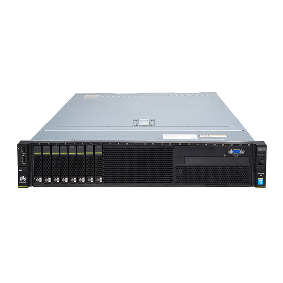
2 Overview 2.2 Appearance Front Panel Figure 2-2 shows the front panel of an RH2288 V3 with eight 2.5-inch hard disks. Figure 2-2 Front panel of an RH2288 V3 with eight 2.5-inch hard disks Fault diagnosis LED Health indicator UID button/indicator... - Page 21 Network port link status indicators (numbered 1 to 4 from top to bottom) Figure 2-5 shows the front panel of an RH2288 V3 with twelve 3.5-inch hard disks, including four NVMe PCIe SSDs. Issue 32 (2019-03-28) Copyright © Huawei Technologies Co., Ltd.
- Page 22 RH2288 V3 Server User Guide 2 Overview Figure 2-5 Front panel of an RH2288 V3 with twelve 3.5-inch hard disks, including four NVMe PCIe SSDs Fault diagnosis LED Health indicator UID button/indicator Power button/indicator Right mounting ear NVMe PCIe SSD yellow indicator...
- Page 23 Hard disk fault indicator Hard disk activity indicator Figure 2-7 shows the front panel of an RH2288 V3 with twenty-five 2.5-inch hard disks. Figure 2-7 Front panel of an RH2288 V3 with twenty-five 2.5-inch hard disks Fault diagnosis LED Health indicator...
- Page 24 4 is equipped with two hard disks, the disks are numbered A1 and B1 from top to bottom. Flexible NICs The RH2288 V3 supports the following models of flexible NICs: SM211: provides two GE electrical ports. SM210/SM212: provides four GE electrical ports.
- Page 25 Figure 2-11 SM233 ports and indicators Transmission rate indicator Connection status indicator/Data transmission status indicator Figure 2-12 SM231 ports and indicators Data transmission status Connection status indicator indicator Figure 2-13 SM252 port and indicators Issue 32 (2019-03-28) Copyright © Huawei Technologies Co., Ltd.
- Page 26 Connection status indicator Data transmission status indicator PCIe Slot Layout Figure 2-15 shows the PCIe slot layout of the RH2288 V3. Figure 2-15 PCIe slot layout PCIe Devices The I/O module provides slots 6 to 8. The I/O module supports 2-slot PCIe riser module or 3-slot PCIe riser module, but three slots are always displayed on the panel.
- Page 27 00/02/0 A flexible — ible NIC with four network ports is used as an example. The four network port numbers are as follows: l 02/00/0 l 02/00/1 l 02/00/2 l 02/00/3 Issue 32 (2019-03-28) Copyright © Huawei Technologies Co., Ltd.
- Page 28 A 3-slot PCIe riser module does not support any GPU. ESNs An Equipment Serial Number (ESN) is a string that uniquely identifies a server. An ESN is required when you apply for technical support from Huawei. Figure 2-16 shows the ESN format by using the example 2102310QPD10F3001263.
-
Page 29: Ports
Indicates the vendor code (two characters). Indicates the year and month (two characters). Indicates the serial number (six characters). 2.3 Ports Table 2-3 Table 2-4 describe the external ports on the RH2288 V3. Table 2-3 Ports on the front panel Port Type Quantity Description Video... -
Page 30: Indicators And Buttons
NIC configured. 2.4 Indicators and Buttons Front Panel You can observe the indicators to determine the status of the RH2288 V3. Table 2-6 describes the indicators and buttons on the RH2288 V3 front panel. Table 2-5 Indicators and buttons on the front panel... - Page 31 RAID status to determine whether the RAID array status is abnormal or whether the hard disk is faulty. For details about command description, see Huawei V2&V3 Server RAID Controller Card User Guide. Issue 32 (2019-03-28) Copyright © Huawei Technologies Co., Ltd.
- Page 32 If the flexible NIC provides two network ports, they correspond to network port indicators 1 and 2 on the front panel. Table 2-5 describes the NVMe PCIe SSD indicators on the RH2288 V3 front panel. Table 2-6 NVMe PCIe SSD indicators Green Indicator Yellow...
- Page 33 For details about command description, see Huawei V2&V3 Server RAID Controller Card User Guide. Table 2-8 describes the indicators of LANs on motherboard (LOMs) on the RH2288 V3 rear panel. Issue 32 (2019-03-28) Copyright © Huawei Technologies Co., Ltd.
- Page 34 SM212 i350 Acti Yello No data is flexible transmitte d on the with network. four Blinking Data is 2.293 being electric transmitte al ports d on the network. Issue 32 (2019-03-28) Copyright © Huawei Technologies Co., Ltd.
- Page 35 Blinking Data is 2.5 Hz 10GE being optical transmitte ports d on the network. Link Green network connectio Steady on network Blinking 2.0 Hz connectio n is normal. Issue 32 (2019-03-28) Copyright © Huawei Technologies Co., Ltd.
- Page 36 Steady on No data is transmitte d on the network. network connectio SM251 Acti Green Steady on flexible network connectio with n is normal. 56G IB optical port Issue 32 (2019-03-28) Copyright © Huawei Technologies Co., Ltd.
-
Page 37: Physical Structure
Blinking Data is being transmitte d on the network. network connectio 2.5 Physical Structure Figure 2-17 shows the components of an RH2288 V3 with 12 hard disks. Issue 32 (2019-03-28) Copyright © Huawei Technologies Co., Ltd. - Page 38 RH2288 V3 Server User Guide 2 Overview Figure 2-17 RH2288 V3 components Rear hard disk module PCIe card on the mainboard PCIe card on a riser card I/O module Internal cable guide Chassis PSU backplane Air duct Supercapacitor tray Supercapacitor...
- Page 39 RH2288 V3 Server User Guide 2 Overview Table 2-9 describes the RH2288 V3 components. Table 2-9 RH2288 V3 components No. Compone Description Rear hard Supported configurations: disk l Two 2.5-inch hard disk slots module l Two 3.5-inch hard disk slots PCIe card Two half-height half-length PCIe 3.0 x8 slots for standard PCIe cards...
- Page 40 Supplies power to hard disks and provides data transmission channels. backplane The RH2288 V3 supports six types of hard disk backplanes for connecting to 8 x 2.5-inch, 8 x 3.5-inch, 12, 12 (including NVMe PCIe SSDs), 24, and 25 hard disks respectively.
- Page 41 Memory speed: DDR4 1866 MT/s, 2133 MT/s, or 2400 MT/s CPUs Process data. Up to two E5-2600 v3 or v4 series CPUs To provide powerful data processing functions, the RH2288 V3 has CPUs integrated with memory controllers and PCIe controllers. The server supports the following CPU configurations: ®...
- Page 42 1920 pixels x 1200 pixels while other OSs only support the maximum resolution supported by the built-in drivers. l If the resolution is greater than 1024 x 768, the display effect may be affected. Issue 32 (2019-03-28) Copyright © Huawei Technologies Co., Ltd.
- Page 43 SATADOMs cannot be used in cache scenarios. l SATADOMs and built-in driver SATA ports are exchangeable. l The RH2288 V3 supports two SATADOMs. The mappings between the physical positions and the port numbers in the BIOS are as follows: SATA1 –...
-
Page 44: Mainboard Layout
One IB flexible NIC with one or two 56G IB optical ports. The flexible NIC does not support NC-SI. NOTE To query information about the flexible NICs supported by the RH2288 V3, use Huawei Server Compatibility Checker. 2.6 Mainboard Layout Figure 2-18 shows the mainboard layout. - Page 45 CPU 1, J50 X8 PCIE SLOT HH/HL) I/O card connector (J46-J45) PCH Mini-SAS HD connector B (J1002) PCH Mini-SAS HD connector A (J1001) Rear disk backplane power connector 1 (J28 PWR CONN2) Issue 32 (2019-03-28) Copyright © Huawei Technologies Co., Ltd.
-
Page 46: Internal Cabling
Internal Cabling for an M.2 SSD Riser Card on a Server with a DVD Drive For an RH2288 V3 with a DVD drive, an M.2 SSD riser card can be configured with only one M.2 SATA SSD card, which uses the external SATA2 port. - Page 47 Internal Cabling for an M.2 SSD Riser Card on a Server Without a DVD Drive For an RH2288 V3 without a DVD drive, an M.2 SSD riser card can be configured with two M.2 SATA SSD cards, which use the external SATA1 and SATA2 ports.
- Page 48 SATA cable for connecting the SATA1 port of an M.2 04051409 SSD riser card to the mainboard (J37) SATA cable for connecting the SATA2 port of an M.2 04051409 SSD riser card to the mainboard (J38) Issue 32 (2019-03-28) Copyright © Huawei Technologies Co., Ltd.
-
Page 49: Internal Cabling For 8-Disk Configuration 1
(J11) SAS cable for connecting Port B (J29) of the front 04051021 (LSI disk backplane to Port B of the RAID controller card SAS3008/3108) on the mainboard 04051024 (LSI SAS2308/2208) Issue 32 (2019-03-28) Copyright © Huawei Technologies Co., Ltd. -
Page 50: Internal Cabling For 8-Disk Configuration 2
(J43) Signal cable for connecting the front VGA board to the 04051076 front disk backplane (J26) Power cable for connecting the DVD drive to the front 04050689 disk backplane (J11) Issue 32 (2019-03-28) Copyright © Huawei Technologies Co., Ltd. - Page 51 (J24) to the mainboard (J30 PWR CONN1) Internal Cabling for a Server with a RAID Controller Card on the Mainboard Figure 2-23 Internal cabling for a server with a RAID controller card on the mainboard Issue 32 (2019-03-28) Copyright © Huawei Technologies Co., Ltd.
-
Page 52: Internal Cabling For 12-Disk Configuration
(J24) to the mainboard (J30 PWR CONN1) 2.7.4 Internal Cabling for 12-Disk Configuration Internal Cabling for 12-Disk Configuration 1 With one RAID controller card and four optional rear hard disks Issue 32 (2019-03-28) Copyright © Huawei Technologies Co., Ltd. - Page 53 PSUs. The cable length limit prevents this cable from being connected to the other rear drive backplane. If a one-to-two SAS cable is incorrectly connected, a disk error alarm is generated on the iBMC WebUI. Issue 32 (2019-03-28) Copyright © Huawei Technologies Co., Ltd.
- Page 54 (J1) to the mainboard (J29 PWR CONN3) Internal Cabling for 12-Disk Configuration 2 With one RAID controller card, four optional NVMe PCIe SSDs, and two optional rear hard disks Figure 2-25 Internal cabling for 12-disk configuration 2 Issue 32 (2019-03-28) Copyright © Huawei Technologies Co., Ltd.
- Page 55 Port 0) SAS cable for — 04051021 (LSI connecting Port A SAS3008/3108) (J28) of the front 04051024 (LSI disk backplane to SAS2308/2208) Port A of the RAID controller card on the mainboard Issue 32 (2019-03-28) Copyright © Huawei Technologies Co., Ltd.
- Page 56 — 04150997 connecting the front disk backplane (J24) to the mainboard (J30 PWR CONN1) Power cable for 04150448-001 — connecting the rear disk backplane (J1) to the mainboard (J29 PWR CONN3) Issue 32 (2019-03-28) Copyright © Huawei Technologies Co., Ltd.
-
Page 57: Internal Cabling For 24-Disk Configuration
2.7.5 Internal Cabling for 24-Disk Configuration Internal Cabling for a Server with One RAID Controller Card The RH2288 V3 does not support rear hard disks if it is configured with one RAID controller card. Figure 2-26 Internal cabling for a server with one RAID controller card No. - Page 58 Internal Cabling for a Server with Two RAID Controller Cards The RH2288 V3 does not support rear hard disks if it is configured with two RAID controller cards, which include one RAID controller card in a standard PCIe slot and one on the mainboard.
- Page 59 RAID controller card 1 (adapter Internal Cabling for a Server with Three RAID Controller Cards The RH2288 V3 does not support rear hard disks if it is configured with three RAID controller cards, including two in standard PCIe slots and one on the mainboard.
- Page 60 SAS cable for connecting Port B (J31) of the 04051021 front disk backplane to Port B of the RAID (LSI controller card in a standard PCIe slot SAS3008/310 04051024 (LSI SAS2308/220 Issue 32 (2019-03-28) Copyright © Huawei Technologies Co., Ltd.
- Page 61 Table 2-11 shows the mapping between the slot numbers in the LSI Logic SAS BIOS CU and the panel silkscreens when the RH2288 V3 is configured with a front 24-disk backplane and three RAID controller cards. Table 2-11 Mapping between the slot numbers in the RAID CU and the panel silkscreens (3 RAID controller cards) Adapter No.
-
Page 62: Internal Cabling For 25-Disk Configuration
Port B of the RAID controller card on the SAS3008/3108) mainboard 04051022 (LSI SAS2308/2208) Signal cable for connecting the front disk backplane 04051053 (J35) to the rear disk backplane (J24) Issue 32 (2019-03-28) Copyright © Huawei Technologies Co., Ltd. -
Page 63: Logical Structure
(J1) to the mainboard (J28 PWR CONN2) Power cable for connecting the rear disk backplane 04150448-001 (J1) to the mainboard (J29 PWR CONN3) 2.8 Logical Structure Figure 2-30 shows the RH2288 V3 logical structure. Issue 32 (2019-03-28) Copyright © Huawei Technologies Co., Ltd. -
Page 64: Ras Features
2 Overview Figure 2-30 RH2288 V3 logical structure The RH2288 V3 supports two Intel® Xeon® E5-2600 v3 Haswell-EP or E5-2600 v4 Broadwell-EP series CPUs and 16 DIMMs. CPUs are connected over QuickPath Interconnect (QPI) buses at up to 9.6 GT/s. - Page 65 Identifies the memory storage unit that contains containment mode corrupted data to minimize the impact on running programs and improve system reliability. Socket disable for FRB Isolates a faulty socket during startup to improve system reliability. Issue 32 (2019-03-28) Copyright © Huawei Technologies Co., Ltd.
-
Page 66: Software And Hardware Compatibility
DIMM errors, and the OS traces and predicts errors, and isolates error memory pages. 2.10 Software and Hardware Compatibility The RH2288 V3 supports a variety of operating systems (OSs), including Windows, SUSE Linux Enterprise Server (SLES), and Red Hat Enterprise Linux (RHEL). Use the Huawei... -
Page 67: Technical Specifications
The NVMe PCIe SSD driver must be 2012 manually installed. Windows Windows Server 2012 R2 2.11 Technical Specifications Table 2-14 describes the RH2288 V3 technical specifications. Table 2-14 Technical specifications Item Specifications Form factor 2U rack server ® ® l Up to two Intel... - Page 68 User Guide 2 Overview Item Specifications RAID support The RH2288 V3 supports the following models of RAID controller cards: l SR320 or SR420: – Uses the LSI SAS2208 chip. – Supports RAID 0, 1, 10, 5, 50, 6, and 60.
- Page 69 2.5-inch SAS HDDs, SATA HDDs, and SSDs at the rear of the server to expand the local storage capacity. l If SATADOM SoftRAID is used when NVMe PCIe SSDs are configured, only the Legacy mode can be selected for the BIOS. Issue 32 (2019-03-28) Copyright © Huawei Technologies Co., Ltd.
- Page 70 One 56G IB optical port. The flexible NIC does not support NC-SI, WOL, or PXE. l The RH2288 V3 provides one PCIe 3.0 x8 slot dedicated for a RAID PCIe slot controller card and five standard PCIe 3.0 x8 slots.
- Page 71 – Provides the GUI, virtual KVM, virtual media, Serial Over LAN (SOL), smart power control, remote control, and hardware monitoring features. l NC-SI l Huawei eSight management software and integration with third-party management systems, such as VMware vCenter, Microsoft SystemCenter, and Nagios Security...
-
Page 72: Physical And Environmental Specifications
If the resolution is greater than 1024 x 768, the display effect may be affected. 2.12 Physical and Environmental Specifications Table 2-15 describes the physical and environmental specifications of the RH2288 V3. Table 2-15 Physical and environmental specifications Item... - Page 73 Long-term storage temperature: 21°C to 27°C (69.8°F to 80.6°F) NOTE l The RH2288 V3 can operate at the highest temperature of 35°C (95°F) when it is configured with rear hard disks, and can operate at the highest temperature of 30°C (86°F) when one fan fails.
- Page 74 There is no explosive, conductive, magnetic, or corrosive dust in the equipment room. Power The power consumption changes depending on the server consumption configuration. Use the Huawei Server Power Calculator calculate the power. Issue 32 (2019-03-28) Copyright © Huawei Technologies Co., Ltd.
-
Page 75: Installing And Removing The Server
"Safety" in the Server Product Documentation. Installation Guidelines The RH2288 V3 is 2U high and can be installed in a standard 19-inch cabinet. The server can be installed on L-shaped, adjustable, and holding rails, and is stackable. If the cabinet has sufficient space, a distance of 1U or more can be reserved between servers. -
Page 76: Installation Environment
To allow for servicing and adequate airflow, observe the following space and airflow requirements: Install the RH2288 V3 in an access-restricted area. Keep the area in which the server is located clean and tidy. For easy heat dissipation and maintenance, keep a clearance of 800 mm (31.50 in.) between walls and the front and rear doors of the cabinet. -
Page 77: Temperature And Humidity Requirements
3.2.3 Cabinet Requirements The cabinet must meet the following requirements: A standard 19-inch cabinet with a depth of more than 1000 mm (39.37 in.). Complies with International Electrotechnical Commission 297 (IEC 297). Issue 32 (2019-03-28) Copyright © Huawei Technologies Co., Ltd. -
Page 78: Unpacking The Chassis
This section describes how to install a server on L-shaped guide rails, adjustable guide rails, and holding rails. Choose an installation method based on site conditions. Install a server if: Additional servers are required in a cabinet for capacity expansion. Issue 32 (2019-03-28) Copyright © Huawei Technologies Co., Ltd. -
Page 79: Installing The Server On L-Shaped Guide Rails
RH2288 V3 Server User Guide 3 Installing and Removing the Server A faulty server needs to be replaced with a new RH2288 V3. A different rack server needs to be replaced with the server. A server component needs to be maintained. - Page 80 See Figure 3-5. Figure 3-5 Installing an L-shaped guide rail Tighten the screws. Install the other guide rail using the same method. Step 3 Install the RH2288 V3. Issue 32 (2019-03-28) Copyright © Huawei Technologies Co., Ltd.
-
Page 81: Installing The Server On Adjustable Guide Rails
3 Installing and Removing the Server Lift the RH2288 V3 and move it to the cabinet. This task requires at least two people. Place the RH2288 V3 onto the guide rails and slide it into the cabinet. See step (1) in Figure 3-6. - Page 82 Step 2 Install the RH2288 V3. Lift the RH2288 V3 and move it to the cabinet. This task requires at least two people. Place the RH2288 V3 onto the guide rails and slide it into the cabinet. See step (1) in Figure 3-8.
-
Page 83: Installing The Server On Holding Rails
3 Installing and Removing the Server Figure 3-8 Installing the RH2288 V3 When the two mounting ears of the RH2288 V3 come into contact with the mounting bars on the cabinet, tighten the captive screws on the mounting ears to secure the RH2288 V3. - Page 84 See step (6) in Figure 3-9. Install the other guide rail using the same method. Step 2 Install the server. Pull out the inner rails as far as they will go. See Figure 3-10. Issue 32 (2019-03-28) Copyright © Huawei Technologies Co., Ltd.
- Page 85 Figure 3-10 Pulling out an inner rail Aligning the nail heads on the server with their L-shaped cutouts on the rails, place the server onto the rails. See step (1) in Figure 3-11. Issue 32 (2019-03-28) Copyright © Huawei Technologies Co., Ltd.
- Page 86 Press the release buttons on both sides and push the server into the cabinet until the mounting ears are in close contact with the mounting bars of the cabinet. See steps (1) and (2) in Figure 3-12. Issue 32 (2019-03-28) Copyright © Huawei Technologies Co., Ltd.
- Page 87 Step 3 Connect a network cable, a VGA cable, or USB devices as required, and connect power cables. Step 4 (Optional) Install the CMA. Insert the support lever into the outer rails on both the left and right sides. See step (1) in Figure 3-13. Issue 32 (2019-03-28) Copyright © Huawei Technologies Co., Ltd.
- Page 88 CMA, and pull the CMA out to secure it. See step (3) in Figure 3-13. Step 5 (Optional) If a CMA is installed, route the external cables connected to the server into the CMA. See Figure 3-14. Issue 32 (2019-03-28) Copyright © Huawei Technologies Co., Ltd.
-
Page 89: Connecting External Cables
RH2288 V3 Server User Guide 3 Installing and Removing the Server Figure 3-14 CMA cabling Step 6 Power on the RH2288 V3. ----End 3.5 Connecting External Cables This section describes how to connect cables to the server. 3.5.1 Connecting Cables to a Mouse, Keyboard, and VGA Port After powering on the server, connect cables to a mouse, keyboard, and VGA port to set the BIOS and RAID, and log in to the OS. -
Page 90: Connecting A Network Cable
The following tools are available: Phillips screwdriver: used to tighten screws ESD wrist strap or ESD gloves: used to prevent ESD damage Diagonal pliers: used to trim the cable ties after binding cables Issue 32 (2019-03-28) Copyright © Huawei Technologies Co., Ltd. - Page 91 Connect the new network cable to the same port as the removed one. Install the network cable in the network port securely. Figure 3-16 Connecting a network cable to management and service network ports Issue 32 (2019-03-28) Copyright © Huawei Technologies Co., Ltd.
-
Page 92: Connecting A Cable To A 10Ge Port
Bend an optical or SFP+ cable with a bending radius of at least 4 cm (1.57 in.) to prevent damage to core wires. Ensure that the cable is intact. Ensure that optical or SFP+ cables are laid out for easy maintenance and capacity expansion. Issue 32 (2019-03-28) Copyright © Huawei Technologies Co., Ltd. - Page 93 Remove the old SFP+ cable. Gently push the power connector inwards and pull the latch out to remove the SFP+ cable. See Figure 3-18. Do not directly pull the latch out. Issue 32 (2019-03-28) Copyright © Huawei Technologies Co., Ltd.
- Page 94 When you hear a "click" and the cable cannot be pulled out, the connector is secured. Figure 3-19 Connecting an SFP+ cable Step 6 Check that the new cable is properly connected. Issue 32 (2019-03-28) Copyright © Huawei Technologies Co., Ltd.
-
Page 95: Connecting A 56G Ib Cable
Step 4 Replace the cable. Remove the old 56G IB cable. Release the latch and remove the cable. See Figure 3-20. Issue 32 (2019-03-28) Copyright © Huawei Technologies Co., Ltd. - Page 96 When you hear a "click" and the cable cannot be pulled out, the connector is secured. Figure 3-21 Connecting a 56G IB cable (using an IB flexible NIC with two 56G ports as an example) Issue 32 (2019-03-28) Copyright © Huawei Technologies Co., Ltd.
-
Page 97: Connecting A Usb Device
You can set it as the iBMC serial port using the iBMC CLI. The serial port can be used in the following scenarios: Issue 32 (2019-03-28) Copyright © Huawei Technologies Co., Ltd. -
Page 98: Connecting A Power Cable
Before connecting power cables, ensure that the server and its internal components have been installed, and the PGND cable is connected to the server (for the RH2288 V3, which does not provide ground terminals, connect the PGND cable to the cabinet where the server is located). - Page 99 (secured with the PSU using a plastic clip). Slide the plastic clip towards the PSU socket to ensure that the plastic clip is close to the connector of the power Issue 32 (2019-03-28) Copyright © Huawei Technologies Co., Ltd.
- Page 100 Step 3 Connect the other end of the power cable to the DC power distribution frame (PDF) based on the power cable connection rules. Step 4 Bind the power cable to the cable trough using cable ties. ----End Issue 32 (2019-03-28) Copyright © Huawei Technologies Co., Ltd.
-
Page 101: Laying Out Cables
Place the connectors of all service data cables at the bottom of the cabinet in order so that the connectors are difficult to reach. Cable Routing Rules To ensure optimal heat dissipation, do not block the air exhaust vents of PSUs. Issue 32 (2019-03-28) Copyright © Huawei Technologies Co., Ltd. -
Page 102: Verifying Cable Connections
NOTE Remove power cables first to prevent damage or injury caused by static electricity. Step 4 Remove the server. Loosen the captive screws on the RH2288 V3 panel using a screwdriver. See step (1) in Figure 3-27. Issue 32 (2019-03-28) - Page 103 Step 5 Loosen the screws that secure a guide rail. See Figure 3-28. Figure 3-28 Removing an L-shaped guide rail Step 6 Remove the other guide rail on the opposite side in the same way. ----End Issue 32 (2019-03-28) Copyright © Huawei Technologies Co., Ltd.
-
Page 104: Removing A Server And Adjustable Guide Rail
Place the removed server on an ESD platform. Step 5 Loosen the four screws on the guide rail. See (1) in Figure 3-30. Step 6 Shorten the guide rail and take it out. See (2) in Figure 3-30. Issue 32 (2019-03-28) Copyright © Huawei Technologies Co., Ltd. -
Page 105: Removing The Server And Holding Rails
Step 3 Disconnect all power cables and signal cables from the server. Step 4 Remove the server. Loosen the captive screws on the server panel using a screwdriver. See (1) in Figure 3-31. Issue 32 (2019-03-28) Copyright © Huawei Technologies Co., Ltd. - Page 106 See (2) in Figure 3-31. Pull the release button upwards, and pull the server out. See (1) and (2) in Figure 3-32. Figure 3-32 Removing a server from holding rails Issue 32 (2019-03-28) Copyright © Huawei Technologies Co., Ltd.
- Page 107 Hold down the plate on the front end of the holding rail and pull out the hook. See (1) and (2) in Figure 3-33. Figure 3-33 Removing a holding rail Push the holding rail out of the square holes. See (3) in Figure 3-33. Issue 32 (2019-03-28) Copyright © Huawei Technologies Co., Ltd.
- Page 108 Lift the positioning pin and remove the holding rail from the square holes. See (6) and (7) in Figure 3-33. Step 6 Remove the other guide rail on the opposite side in the same way. ----End Issue 32 (2019-03-28) Copyright © Huawei Technologies Co., Ltd.
-
Page 109: Powering On And Off The Server
PSUs. To change the value of Power Strategy, log in to the iBMC WebUI and choose Power > Power Control. If PSUs are powered on and the server is in the standby state, power on the server as follows: Issue 32 (2019-03-28) Copyright © Huawei Technologies Co., Ltd. - Page 110 Figure 4-1 Power Control page Click Power On. In the displayed dialog box, click Yes to power on the server. Verification Check the indicator status after the server is powered on. Issue 32 (2019-03-28) Copyright © Huawei Technologies Co., Ltd.
-
Page 111: Powering Off The Server
After powering off the server, wait at least 1 minute to ensure that the server is completely powered off. Then, you can power on the server again. Procedure Power off the server using the iBMC WebUI. Issue 32 (2019-03-28) Copyright © Huawei Technologies Co., Ltd. - Page 112 The Power Control page is displayed, as shown in Figure 4-2. Figure 4-2 Power Control page Click Power Off. In the displayed dialog box, click Yes to power off the server. Issue 32 (2019-03-28) Copyright © Huawei Technologies Co., Ltd.
-
Page 113: Configuring The Rh2288 V3
User Guide 5 Configuring the RH2288 V3 Configuring the RH2288 V3 About This Chapter This section describes how to configure the RH2288 V3 after it is installed. 5.1 Default Information 5.2 Configuration Process 5.3 Checking the RH2288 V3 5.4 Configuring RAID 5.5 Configuring the BIOS... -
Page 114: Configuration Process
RH2288 V3 Server User Guide 5 Configuring the RH2288 V3 Item Parameter Default Value BIOS Password The default BIOS password is Huawei12#$ for the American keyboard, Huqzei&é34 for the French keyboard, and Huawei12£$ for the English keyboard. NOTE When entering the BIOS password on the... -
Page 115: Checking The Rh2288 V3
Huawei Server OS Installation Guide. 5.3 Checking the RH2288 V3 Log in to the iBMC WebUI or CLI to check the health status of the RH2288 V3. Ensure that its health status meets the environment requirements for software installation. Table1 Default information describes the default information for logging in to the RH2288 V3 iBMC WebUI or CLI. - Page 116 OS. Workflow Check the RH2288 V3 by following the sequence described in Figure 5-2. Determine the check method based on site requirements. Figure 5-2 Process for checking the RH2288 V3 Issue 32 (2019-03-28) Copyright ©...
- Page 117 RH2288 V3 Server User Guide 5 Configuring the RH2288 V3 Procedure Check indicator status. Observe the RH2288 V3 indicator status, and check that hardware devices are properly operating. For details, see 2.4 Indicators and Buttons. Check the RH2288 V3 using the iBMC WebUI.
- Page 118 Set an IP address for the PC, and ensure that the IP address is on the same network segment as the iBMC management network port. Connect the PC to the RH2288 V3 iBMC management network port by using a network cable.
-
Page 119: Configuring Raid
(CPLD) version of the RH2288 V3. BIOS Version: indicates the BIOS version of the RH2288 V3. Active iBMC Version: indicates the active iBMC version of the RH2288 V3. Backup iBMC Version: indicates the backup iBMC version of the RH2288 Query the health status for the RH2288 V3. -
Page 120: Configuring The Bios
SP435 (PM8060), and SR135 (PM8068) 5.5 Configuring the BIOS Configure the BIOS of the RH2288 V3, including setting the server boot mode, selecting PXE as a boot option, enabling the PXE function for a network port, and setting the BIOS Issue 32 (2019-03-28) Copyright ©... - Page 121 RH2288 V3 Server User Guide 5 Configuring the RH2288 V3 password and language. For details about how to configure the BIOS, see the Huawei Server Grantley Platform BIOS Parameter Reference. Workflow Figure 5-7 shows the process for configuring the BIOS.
- Page 122 RH2288 V3 Server User Guide 5 Configuring the RH2288 V3 Press Delete repeatedly when the screen shown in the following figure is displayed during server startup. The BIOS Setup Utility starts. NOTE You can also press the following shortcut keys on the BIOS startup screen as required: l Press F5 to select the keyboard type (English,American or French keyboard).
- Page 123 RH2288 V3 Server User Guide 5 Configuring the RH2288 V3 Choose Boot > Boot Type and press Enter. The Boot screen is displayed, as shown in Figure 5-9. Figure 5-9 Boot In the displayed dialog box, select Dual Boot Type, Legacy Boot Type, or UEFI Type, and press Enter.
- Page 124 RH2288 V3 Server User Guide 5 Configuring the RH2288 V3 Figure 5-10 Boot Type Order Select PXE as a boot option. Select boot options to be configured, and press + or - to change the boot sequence. Set the first boot option to PXE.
- Page 125 RH2288 V3 Server User Guide 5 Configuring the RH2288 V3 Figure 5-11 PXE Configuration 11. Select the network port to be configured, and press Enter. 12. Choose Enabled from the shortcut menu and press Enter to enable the PXE function for the network port.
- Page 126 RH2288 V3 Server User Guide 5 Configuring the RH2288 V3 Figure 5-12 Security 14. Select Set Supervisor Password and press Enter. Set a login password for the super administrator. Before changing the supervisor password, you need to enter the current supervisor password.
- Page 127 RH2288 V3 Server User Guide 5 Configuring the RH2288 V3 Figure 5-13 Main screen 16. Select Language and press Enter. The screen for selecting a language is displayed, as shown in Figure 5-14. Figure 5-14 Selecting a language 17. Select English and press Enter. The GUI language is changed to English, as shown in Figure 5-15.
-
Page 128: Changing An Ibmc User Password
RH2288 V3 Server User Guide 5 Configuring the RH2288 V3 Figure 5-15 Main screen 18. Press F10. The Exit Saving changes? dialog box is displayed. 19. Select Yes to save the settings. 5.6 Changing an iBMC User Password Change the default password promptly and change the user password periodically to ensure system security. -
Page 129: Setting The Management Network Port Ip Address
RH2288 V3 Server User Guide 5 Configuring the RH2288 V3 Step 2 Choose Config > Security Enhance. Step 3 Select Enable for Password Complexity Check. The system will perform a password complexity check when a new password is set. Step 4 Choose Config > Local User, as shown in Figure 5-16. - Page 130 RH2288 V3 Server User Guide 5 Configuring the RH2288 V3 Table 5-5 Default information Item Parameter Default Value iBMC management IP address and subnet l IP address: 192.168.2.100 network port mask of the l Subnet mask: 255.255.255.0 information management network...
- Page 131 RH2288 V3 Server User Guide 5 Configuring the RH2288 V3 Click Save. No further action is required. Set the IP address in the BIOS. Click on the menu bar of the Remote Virtual Console. For details about how to log in to the Remote Virtual Console, see 9.7 Opening the...
- Page 132 RH2288 V3 Server User Guide 5 Configuring the RH2288 V3 Figure 5-19 iBMC Configuration Select IP Address in IPV4 Configuration and press Enter. On the configuration screen, set the IPv4 address of the iBMC management network port, as shown in Figure 5-20.
-
Page 133: Installing An Os
RH2288 V3 Server User Guide 5 Configuring the RH2288 V3 5.8 Installing an OS The RH2288 V3 is compatible with different types of OSs, including Windows, SLES, and RHEL. Use the Huawei Server Compatibility Checker to check OSs supported by the server. -
Page 134: Software And Configuration Utility
The BIOS also provides ACPI and hot swap. The BIOS is stored in the serial peripheral interface (SPI) flash memory. The RH2288 V3 server offers a Huawei's proprietary, patented BIOS that uses the Intel Grantley platform and is developed based on the Insyde code base. The BIOS is customizable and scalable, and provides a variety of in-band and out-of-band configuration functions. -
Page 135: Ibmc
6 Software and Configuration Utility 6.2 iBMC The iBMC is a Huawei's proprietary system that remotely manages servers. iBMC complies with IPMI 2.0 and SNMP standards and supports various functions, including KVM redirection, text console redirection, remote virtual media, and hardware monitoring and management. - Page 136 Guide l iBMC management software: RH2288 l FusionServer Tools V100R002 uMate V3-iBMC-V191.zip User Guide l BIOS firmware: RH2288 V3-BIOS- l Huawei Rack Server Upgrade Guide V169.zip (iBMC) l Driver: FusionServer iDriver- l Driver Version Mapping Windows-Driver-V304.zip...
- Page 137 Huawei Server Firmware Upgrade Guide. Upgrade the BIOS, CPLD, and iBMC using the FusionServer Tools uMate. Log in to http://e.huawei.com/en/, choose Support > Server > Server Management Software > FusionServer Tools, and download the uMate package of the latest version.
- Page 138 The driver upgrade procedure varies according to the OS type and version. For details, see the Huawei Server OS Installation Guide. Supported OSs To query the OS versions supported by the server, use the Huawei Server Compatibility Checker. Issue 32 (2019-03-28) Copyright © Huawei Technologies Co., Ltd.
-
Page 139: Replacing Parts
7 Replacing Parts Replacing Parts About This Chapter This section describes the replaceable parts of the RH2288 V3 and how to replace them. l Ensure that the obtained spare parts are compatible and function properly before any replacement. Use the... - Page 140 7.38 Installing a CPU 7.39 Removing a DIMM 7.40 Installing a DIMM 7.41 Removing the Mainboard 7.42 Installing the Mainboard 7.43 Removing the Flexible NIC 7.44 Installing the Flexible NIC 7.45 Removing a SATADOM Issue 32 (2019-03-28) Copyright © Huawei Technologies Co., Ltd.
-
Page 141: Replaceable Parts
7.62 Installing the Right Mounting Ear 7.63 Removing an M.2 SATA SSD Card 7.64 Installing an M.2 SATA SSD Card 7.1 Replaceable Parts The RH2288 V3 is 2U high and has the following replaceable parts: Front bezel (optional) Mainboard Hard disk... -
Page 142: Tool Preparations
Step 1 Wear an ESD wrist strap. For details, see 1 Safety Instructions. Step 2 Unlock the front bezel by turning the key clockwise, and remove the key for proper storage. Figure 7-1. Issue 32 (2019-03-28) Copyright © Huawei Technologies Co., Ltd. - Page 143 RH2288 V3 Server User Guide 7 Replacing Parts Figure 7-1 Unlocking the front bezel Step 3 Press the button and remove the front bezel. See Figure 7-2. Figure 7-2 Removing the front bezel Issue 32 (2019-03-28) Copyright © Huawei Technologies Co., Ltd.
-
Page 144: Optional) Installing The Front Bezel
Step 2 Remove the key from the front bezel. See Figure 7-3. Figure 7-3 Removing a key Step 3 Unlock the front bezel by turning the key clockwise, and remove the key for proper storage. Figure 7-4. Issue 32 (2019-03-28) Copyright © Huawei Technologies Co., Ltd. - Page 145 Step 4 Hook the front bezel onto the side of the left mounting ear, and press the button so that the front bezel is secured to the chassis. See Figure 7-5. Issue 32 (2019-03-28) Copyright © Huawei Technologies Co., Ltd.
- Page 146 User Guide 7 Replacing Parts Figure 7-5 Installing the front bezel Step 5 Lock the front bezel by turning the key counterclockwise, and remove the key for proper storage. See Figure 7-6. Issue 32 (2019-03-28) Copyright © Huawei Technologies Co., Ltd.
-
Page 147: Removing A Hard Disk
Remove a hard disk before replacing it with a new one. You do not need to power off the RH2288 V3 before removing a hard disk. If services are running on the RH2288 V3, you have backed up the data stored on the hard disk to be removed. - Page 148 Step 3 If a front hard disk needs to be removed and the server is equipped with a front bezel, remove the bezel. For details, see 7.3 (Optional) Removing the Front Bezel. Step 4 Determine the position of the hard disk (for example, a front hard disk) on the RH2288 V3. Figure 7-7. Figure 7-7 Hard disk position Issue 32 (2019-03-28) Copyright ©...
-
Page 149: Installing A Hard Disk
Install a hard disk to replace the original one or add a new hard disk. You do not need to power off the RH2288 V3 before installing a hard disk. After a failed hard disk is disconnected from the disk backplane, wait for 30 seconds before removing it and inserting a new one. -
Page 150: Removing An Nvme Pcie Ssd
Remove an AC PSU before replacing it with a new one. When two PSUs are configured, remove one PSU without powering off the RH2288 V3 if the other PSU is operating properly and its power rating is greater than or equal to the power rating of the RH2288 V3. - Page 151 Step 2 Determine the cabinet number and chassis number of the server to be removed, and label its panel to prevent misoperations. Step 3 If only one PSU is configured, power off the RH2288 V3. For details, see 4.2 Powering Off Server.
-
Page 152: Removing A Dc Psu
Step 1 Wear an ESD wrist strap. For details, see 1 Safety Instructions. Step 2 Determine the cabinet number and chassis number of the server to be removed, and label its panel to prevent misoperations. Issue 32 (2019-03-28) Copyright © Huawei Technologies Co., Ltd. - Page 153 Figure 7-13 Removing power cables Step 4 Hold down the latch on the PSU, and pull out part of the PSU by holding the handle. See step (1) in Figure 7-14. Issue 32 (2019-03-28) Copyright © Huawei Technologies Co., Ltd.
-
Page 154: Installing A Psu
Step 4 Push the spare AC PSU along the guide rails into a slot until the PSU clicks into place. The PSU latch snaps in so that the PSU does not move. See Figure 7-15. Issue 32 (2019-03-28) Copyright © Huawei Technologies Co., Ltd. - Page 155 Figure 7-16 Connecting a power cable (secured with the PSU using a velcro strap) If the PSU has a plastic clip, perform the following steps to connect the power cable: Issue 32 (2019-03-28) Copyright © Huawei Technologies Co., Ltd.
-
Page 156: Installing A Dc Psu
----End 7.10.2 Installing a DC PSU Install a DC PSU to replace the original one. A DC PSU needs to be added to improve reliability when the RH2288 V3 is configured with only one DC PSU. Procedure Step 1 Wear an ESD wrist strap. For details, see 1 Safety Instructions. - Page 157 Connect the OT terminal on the positive power cable to the RTN(+) wiring terminal on the PSU. Connect the OT terminal on the ground cable to the ground terminal on the PSU. Issue 32 (2019-03-28) Copyright © Huawei Technologies Co., Ltd.
-
Page 158: Removing The Chassis Cover
4.2 Powering Off the Server. Step 4 Remove all external cables such as power and network cables. Step 5 Remove the RH2288 V3 and put it on an ESD desktop. For details, see 3.6 Removing the Server. Step 6 Loosen the latch that secures the handle of the chassis cover using a flat-head screwdriver. -
Page 159: Installing The Chassis Cover
Step 8 Lift the chassis cover. See step (3) in Figure 7-20. ----End 7.12 Installing the Chassis Cover Install the chassis cover after components in the RH2288 V3 chassis are replaced. Procedure Step 1 Wear an ESD wrist strap. For details, see 1 Safety Instructions. - Page 160 To ensure that the chassis cover fits into place, close the ejector lever while pressing the front end of the chassis cover, as shown in Figure 7-22. If the problem persists, contact Huawei engineers. Issue 32 (2019-03-28) Copyright © Huawei Technologies Co., Ltd.
-
Page 161: Removing The Air Duct
Step 5 Connect all internal cables such as power and network cables. For details, see 3.5 Connecting External Cables. Step 6 Power on the RH2288 V3. For details, see 4.1 Powering On the Server. ----End 7.13 Removing the Air Duct Remove the air duct before replacing it with a new one or replacing a CPU, DIMM, or supercapacitor. -
Page 162: Installing The Air Duct
RH2288 V3 Server User Guide 7 Replacing Parts Step 5 Remove the RH2288 V3 and put it on an ESD desktop. For details, see 3.6 Removing the Server. Step 6 Remove the chassis cover. For details, see 7.11 Removing the Chassis Cover. - Page 163 See Figure 7-25. Figure 7-25 Installing the air duct Step 5 (Optional) Install the supercapacitor tray on the air duct in the arrow direction. See Figure 7-26. Issue 32 (2019-03-28) Copyright © Huawei Technologies Co., Ltd.
-
Page 164: Removing A Fan Module
Server. Step 9 Connect all external cables such as power and network cables. For details, see Connecting External Cables. Step 10 Power on the RH2288 V3. For details, see 4.1 Powering On the Server. ----End 7.15 Removing a Fan Module Remove a fan module before replacing it with a new one or removing other components (such as the mainboard and DVD drive). - Page 165 4.2 Powering Off the Server. Step 4 Remove all external cables such as power and network cables. Step 5 Remove the RH2288 V3 and put it on an ESD desktop. For details, see 3.6 Removing the Server. Step 6 Remove the chassis cover. For details, see 7.11 Removing the Chassis...
-
Page 166: Installing A Fan Module
User Guide 7 Replacing Parts Figure 7-28 Removing a fan module Step 10 Lift the fan module slowly out of the RH2288 V3. See step (2) in Figure 7-28. Step 11 Place the removed fan module in an ESD bag. - Page 167 3.4 Installing the Server. Step 9 Connect all external cables such as power and network cables. For details, see Connecting External Cables. Step 10 Power on the RH2288 V3. For details, see 4.1 Powering On the Server. ----End Issue 32 (2019-03-28)
-
Page 168: Removing An Internal Cable
4.2 Powering Off the Server. Step 4 Remove all external cables such as power and network cables. Step 5 Remove the RH2288 V3 and put it on an ESD desktop. For details, see 3.6 Removing the Server. Step 6 Remove the chassis cover. For details, see 7.11 Removing the Chassis... -
Page 169: Installing An Internal Cable
Step 3 Take a spare cable out of the ESD bag. Step 4 Install the spare cable. For details about cable port positions, see 2.7 Internal Cabling. Step 5 Install fan module brackets in the chassis. See Figure 7-32. Issue 32 (2019-03-28) Copyright © Huawei Technologies Co., Ltd. - Page 170 Figure 7-32 Installing fan module brackets Step 6 Insert fan modules into the slots and ensure that fan module cable connectors fit into the ports on the mainboard. See Figure 7-33. Figure 7-33 Installing fan modules Issue 32 (2019-03-28) Copyright © Huawei Technologies Co., Ltd.
-
Page 171: Removing The Riser Card
4.2 Powering Off the Server. Step 4 Remove all external cables such as power and network cables. Step 5 Remove the RH2288 V3 and put it on an ESD desktop. For details, see 3.6 Removing the Server. Step 6 Remove the chassis cover. For details, see 7.11 Removing the Chassis... -
Page 172: Installing A Riser Card
Step 3 Take the spare riser card out of its ESD bag. Step 4 Push the riser card in the arrow direction until it does not move. See step (1) in Figure 7-36. Issue 32 (2019-03-28) Copyright © Huawei Technologies Co., Ltd. - Page 173 Step 7 Install the riser card tray. See Figure 7-37. Figure 7-37 Installing a riser card tray Step 8 Install the chassis cover. For details, see 7.12 Installing the Chassis Cover. Issue 32 (2019-03-28) Copyright © Huawei Technologies Co., Ltd.
-
Page 174: Removing A Pcie Card
4.2 Powering Off the Server. Step 4 Remove all external cables such as power and network cables. Step 5 Remove the RH2288 V3 and put it on an ESD desktop. For details, see 3.6 Removing the Server. Step 6 Remove the chassis cover. For details, see 7.11 Removing the Chassis... - Page 175 Step 10 Open the PCIe card latch. See step (2) in Figure 7-39. Step 11 Remove the PCIe card. See step (3) in Figure 7-39. Step 12 Place the removed PCIe card in an ESD bag. ----End Issue 32 (2019-03-28) Copyright © Huawei Technologies Co., Ltd.
-
Page 176: Removing A Pcie Card From The Mainboard
4.2 Powering Off the Server. Step 4 Remove all external cables such as power and network cables. Step 5 Remove the RH2288 V3 and put it on an ESD desktop. For details, see 3.6 Removing the Server. Step 6 Remove the chassis cover. For details, see 7.11 Removing the Chassis... -
Page 177: Installing A Pcie Card
Figure 7-41 Installing a PCIe card on the riser card Step 5 Close the latch. See step (2) in Figure 7-41. Step 6 Install the riser card tray. See Figure 7-42. Issue 32 (2019-03-28) Copyright © Huawei Technologies Co., Ltd. -
Page 178: Installing A Pcie Card On The Mainboard
Server. Step 10 Connect all external cables such as power and network cables. For details, see Connecting External Cables. Step 11 Power on the RH2288 V3. For details, see 4.1 Powering On the Server. ----End 7.22.2 Installing a PCIe Card on the Mainboard Install a non-hot-swappable PCIe card to replace the original one. -
Page 179: Removing The Dvd Drive
4.2 Powering Off the Server. Step 4 Remove all external cables such as power and network cables. Step 5 Remove the RH2288 V3 and put it on an ESD desktop. For details, see 3.6 Removing the Server. Issue 32 (2019-03-28) - Page 180 Use the same method to lift the other fan module bracket. See steps (1) and (2) in Figure 7-44. Figure 7-44 Removing fan module brackets Step 10 Remove all cables from the DVD drive. See step (1) in Figure 7-45. Issue 32 (2019-03-28) Copyright © Huawei Technologies Co., Ltd.
- Page 181 4.2 Powering Off the Server. Step 4 Remove all external cables such as power and network cables. Step 5 Remove the RH2288 V3 and put it on an ESD desktop. For details, see 3.6 Removing the Server. Step 6 Remove the chassis cover. For details, see 7.11 Removing the Chassis...
- Page 182 For details, see 2.7 Internal Cabling. Step 12 Use a Phillips screwdriver to unscrew the DVD drive panel. See step (1) in Figure 7-47. Issue 32 (2019-03-28) Copyright © Huawei Technologies Co., Ltd.
- Page 183 Step 14 Hold down the plastic latch on the DVD drive, and push the DVD drive outwards to remove it from the chassis. See steps (2) and (3) in Figure 7-48. Step 15 Place the removed DVD drive in an ESD bag. ----End Issue 32 (2019-03-28) Copyright © Huawei Technologies Co., Ltd.
-
Page 184: Installing The Dvd Drive
7-49. Step 6 Connect cables to the DVD drive. See step (3) in Figure 7-49. NOTE If fan modules have been installed, remove them and the fan support before connecting cables. Issue 32 (2019-03-28) Copyright © Huawei Technologies Co., Ltd. - Page 185 Server. Step 12 Connect all external cables such as power and network cables. For details, see Connecting External Cables. Step 13 Power on the RH2288 V3. For details, see 4.1 Powering On the Server. ----End With Eight 3.5-inch Hard Disks Step 1 Wear an ESD wrist strap.
- Page 186 Step 6 Connect cables to the DVD drive. See step (3) in Figure 7-51. Step 7 Push the DVD drive tray into the chassis. See step (1) in Figure 7-52. Figure 7-52 Installing the DVD drive tray Issue 32 (2019-03-28) Copyright © Huawei Technologies Co., Ltd.
-
Page 187: Removing The Internal Usb Flash Drive
Server. Step 15 Connect all external cables such as power and network cables. For details, see Connecting External Cables. Step 16 Power on the RH2288 V3. For details, see 4.1 Powering On the Server. ----End 7.25 Removing the Internal USB Flash Drive Remove the USB flash drive before replacing it with a new one. -
Page 188: Installing The Internal Usb Flash Drive
4.2 Powering Off the Server. Step 4 Remove all external cables such as power and network cables. Step 5 Remove the RH2288 V3 and put it on an ESD desktop. For details, see 3.6 Removing the Server. Step 6 Remove the chassis cover. For details, see 7.11 Removing the Chassis... -
Page 189: Removing The System Battery
Server. Step 7 Connect all external cables such as power and network cables. For details, see Connecting External Cables. Step 8 Power on the RH2288 V3. For details, see 4.1 Powering On the Server. ----End 7.27 Removing the System Battery Remove the system battery before replacing it with a new one. -
Page 190: Installing The System Battery
4.2 Powering Off the Server. Step 4 Remove all external cables such as power and network cables. Step 5 Remove the RH2288 V3 and put it on an ESD desktop. For details, see 3.6 Removing the Server. Step 6 Remove the chassis cover. For details, see 7.11 Removing the Chassis... - Page 191 3.4 Installing the Server. Step 7 Connect all external cables such as power and network cables. For details, see Connecting External Cables. Step 8 Power on the RH2288 V3. For details, see 4.1 Powering On the Server. ----End Issue 32 (2019-03-28)
-
Page 192: Removing The Screw-In Raid Controller Card
4.2 Powering Off the Server. Step 4 Remove all external cables such as power and network cables. Step 5 Remove the RH2288 V3 and put it on an ESD desktop. For details, see 3.6 Removing the Server. Step 6 Remove the chassis cover. For details, see 7.11 Removing the Chassis... -
Page 193: Installing The Screw-In Raid Controller Card
Step 3 Take the spare RAID controller card out of its ESD bag. Step 4 (Optional) Remove the rubber plugs from the ports on the RAID controller card if any. See Figure 7-60. Issue 32 (2019-03-28) Copyright © Huawei Technologies Co., Ltd. - Page 194 Step 9 Install the chassis cover. For details, see 7.12 Installing the Chassis Cover. Step 10 Install the RH2288 V3. For details, see 3.4 Installing the Server. Step 11 Connect all external cables such as power and network cables. For details, see Connecting External Cables.
-
Page 195: Removing The Pcie Plug-In Raid Controller Card
4.2 Powering Off the Server. Step 4 Remove all external cables such as power and network cables. Step 5 Remove the RH2288 V3 and put it on an ESD desktop. For details, see 3.6 Removing the Server. Step 6 Remove the chassis cover. For details, see 7.11 Removing the Chassis... -
Page 196: Removing The Supercapacitor (Screw-In Raid Controller Card)
Step 9 Connect all external cables such as power and network cables. For details, see Connecting External Cables. Step 10 Power on the RH2288 V3. For details, see 4.1 Powering On the Server. Step 11 Log in to the RAID configuration screen to check whether RAID configuration needs to be imported or activated. - Page 197 4.2 Powering Off the Server. Step 4 Remove all external cables such as power and network cables. Step 5 Remove the RH2288 V3 and put it on an ESD desktop. For details, see 3.6 Removing the Server. Step 6 Remove the chassis cover. For details, see 7.11 Removing the Chassis...
- Page 198 7-63. Step 13 Exert even force to lift the supercapacitor out of the server. See step (5) in Figure 7-63. Step 14 Place the removed supercapacitor in an ESD bag. ----End Issue 32 (2019-03-28) Copyright © Huawei Technologies Co., Ltd.
-
Page 199: Removing The Supercapacitor (Pcie Plug-In Raid Controller Card)
4.2 Powering Off the Server. Step 4 Remove all external cables such as power and network cables. Step 5 Remove the RH2288 V3 and put it on an ESD desktop. For details, see 3.6 Removing the Server. Step 6 Remove the chassis cover. For details, see 7.11 Removing the Chassis... - Page 200 Remove the cable between the supercapacitor and the TFM. See step (3) in Figure 7-65. If the chip model of the RAID controller card is PM8060, remove the cable between the supercapacitor and the RAID controller card. See step (1) in Figure 7-66. Issue 32 (2019-03-28) Copyright © Huawei Technologies Co., Ltd.
-
Page 201: Installing The Supercapacitor (Screw-In Raid Controller Card)
Step 12 Place the removed supercapacitor in an ESD bag. ----End 7.35 Installing the Supercapacitor (Screw-in RAID Controller Card) A supercapacitor is configured to provide power-off protection for an LSI SAS2208 or LSI SAS3108 screw-in RAID controller card. Issue 32 (2019-03-28) Copyright © Huawei Technologies Co., Ltd. - Page 202 Figure 7-67. NOTE Insert the connector with pins to the TFM socket. Step 8 Install the riser card above the RAID controller card. For details, see 7.19 Removing the Riser Card. Issue 32 (2019-03-28) Copyright © Huawei Technologies Co., Ltd.
-
Page 203: Installing The Supercapacitor (Pcie Plug-In Raid Controller Card)
Server. Step 11 Connect all external cables such as power and network cables. For details, see Connecting External Cables. Step 12 Power on the RH2288 V3. For details, see 4.1 Powering On the Server. ----End 7.36 Installing the Supercapacitor (PCIe Plug-in RAID... - Page 204 If the chip model of the RAID controller card connected to the supercapacitor to be installed is PM8060, connect the cable between the supercapacitor and the RAID controller card. See step (2) in Figure 7-69. Issue 32 (2019-03-28) Copyright © Huawei Technologies Co., Ltd.
- Page 205 7.19 Removing the Riser Card. Step 7 Install the chassis cover. For details, see 7.12 Installing the Chassis Cover. Step 8 Install the RH2288 V3. For details, see 3.4 Installing the Server. Issue 32 (2019-03-28) Copyright © Huawei Technologies Co., Ltd.
-
Page 206: Removing A Cpu
4.2 Powering Off the Server. Step 4 Remove all external cables such as power and network cables. Step 5 Remove the RH2288 V3 and put it on an ESD desktop. For details, see 3.6 Removing the Server. Step 6 Remove the chassis cover. For details, see 7.11 Removing the Chassis... - Page 207 Step 10 Use a Phillips screwdriver to loosen one pair of diagonally opposite screws on the heat sink halfway and then loosen the other pair of screws. See step (1) in Figure 7-71. Figure 7-71 Removing the heat sink Issue 32 (2019-03-28) Copyright © Huawei Technologies Co., Ltd.
- Page 208 Ensure that CPU sockets are populated with CPUs or CPU protective covers during transportation and storage. Removing a v4 series CPU Raise the securing rod near the label. See step (1) in Figure 7-73. Issue 32 (2019-03-28) Copyright © Huawei Technologies Co., Ltd.
- Page 209 Ensure that CPU sockets are populated with CPUs or CPU protective covers during transportation and storage. Step 13 (Optional) Install a CPU protective cover. Close the CPU load plate. See step (1) in Figure 7-74. Figure 7-74 Installing a CPU protective cover Issue 32 (2019-03-28) Copyright © Huawei Technologies Co., Ltd.
-
Page 210: Installing A Cpu
Step 3 Take the spare CPU out of its ESD bag. Step 4 Check that CPU socket does not have bent pins and is free from foreign objects. If a CPU socket has bent pins or foreign objects, stop installing the CPU and contact Huawei technical support. - Page 211 Figure 7-77 CPU installation tool with the CPU inside Step 7 Determine the area on the CPU for contacting the heat sink, and apply 0.4 ml of thermal compound on the area. Issue 32 (2019-03-28) Copyright © Huawei Technologies Co., Ltd.
- Page 212 The thermal compound layer is as thick as a common piece of paper. Figure 7-79 shows the smeared thermal compound layer. Ensure that the thermal compound is evenly and fully applied. Figure 7-79 Smeared thermal compound layer Issue 32 (2019-03-28) Copyright © Huawei Technologies Co., Ltd.
- Page 213 7-81. Align the triangle on the CPU with the triangle on the CPU socket to ensure that the CPU is properly installed. Figure 7-82 shows a CPU that is incorrectly placed. Issue 32 (2019-03-28) Copyright © Huawei Technologies Co., Ltd.
- Page 214 7-83. Align the triangle on the CPU with the triangle on the CPU socket to ensure that the CPU is properly installed. Figure 7-84 shows a CPU that is incorrectly placed. Issue 32 (2019-03-28) Copyright © Huawei Technologies Co., Ltd.
- Page 215 Step 10 Align the screws on the heat sink with the fastening studs on the CPU base, and place the heat sink on the CPU. See step (1) in Figure 7-85. Issue 32 (2019-03-28) Copyright © Huawei Technologies Co., Ltd.
-
Page 216: Removing A Dimm
3.4 Installing the Server. Step 16 Connect all external cables such as power and network cables. For details, see Connecting External Cables. Step 17 Power on the RH2288 V3. For details, see 4.1 Powering On the Server. ----End 7.39 Removing a DIMM Remove a DIMM if it has failed or needs to be replaced with a new model. -
Page 217: Installing A Dimm
User Guide 7 Replacing Parts Step 4 Remove all external cables such as power and network cables. Step 5 Remove the RH2288 V3 and put it on an ESD desktop. For details, see 3.6 Removing the Server. Step 6 Remove the chassis cover. For details, see 7.11 Removing the Chassis... - Page 218 User Guide 7 Replacing Parts The RH2288 V3 supports a maximum of eight DIMMs when one CPU is installed and a maximum of sixteen DIMMs when two CPUs are installed. Each CPU comes with four memory channels, and each memory channel supports two DIMMs.
- Page 219 Step 5 Align the DIMM with the DIMM slot, and insert the DIMM into the slot. Press down on the DIMM with your thumbs until it snaps into place. See Figure 7-89. Issue 32 (2019-03-28) Copyright © Huawei Technologies Co., Ltd.
-
Page 220: Removing The Mainboard
3.4 Installing the Server. Step 11 Connect all external cables such as power and network cables. For details, see Connecting External Cables. Step 12 Power on the RH2288 V3. For details, see 4.1 Powering On the Server. ----End 7.41 Removing the Mainboard Remove the mainboard if it has failed. - Page 221 4.2 Powering Off the Server. Step 7 Remove all external cables such as power and network cables. Step 8 Remove the RH2288 V3 and put it on an ESD desktop. For details, see 3.6 Removing the Server. Step 9 Remove the chassis cover. For details, see 7.11 Removing the Chassis...
- Page 222 2.7 Internal Cabling. Remove the FFC cable to avoid cable damage caused by the removal of the mainboard frame. Figure 7-91. If the FFC cable is damaged, the server cannot work. Issue 32 (2019-03-28) Copyright © Huawei Technologies Co., Ltd.
- Page 223 Step 19 Remove the flexible NIC. For details, see 7.43 Removing the Flexible NIC. Step 20 Remove all PSUs. For details, see 7.9 Removing a PSU. Step 21 Lift the PSU backplane. See Figure 7-92. Issue 32 (2019-03-28) Copyright © Huawei Technologies Co., Ltd.
- Page 224 Figure 7-92 Removing a PSU backplane Step 22 Open the latch in arrow direction (1), and remove the cable guide in arrow direction (2). See Figure 7-93. Figure 7-93 Removing a cable guide Issue 32 (2019-03-28) Copyright © Huawei Technologies Co., Ltd.
-
Page 225: Installing The Mainboard
7-94. Figure 7-94 Removing a mainboard Step 24 Push the mainboard in the arrow direction until it does not move, and lift the mainboard out of the RH2288 V3 by holding the handle. See step (2) in Figure 7-94. Do not hold any other protruding part of the mainboard to lift it. Otherwise, the components on the mainboard may be damaged. - Page 226 If CPU sockets have bent pins or foreign objects, stop installing the mainboard and contact Huawei technical support. Step 5 Place the mainboard into the RH2288 V3, and push the mainboard in the arrow direction by holding the handle as far as it will go. See step (1) in Figure 7-95.
- Page 227 7 Replacing Parts Figure 7-96 Installing a cable guide Step 8 Insert the PSU backplane into the slot in the mainboard. See step (1) in Figure 7-97. Figure 7-97 Installing the PSU backplane Issue 32 (2019-03-28) Copyright © Huawei Technologies Co., Ltd.
- Page 228 Step 22 Connect all external cables such as power and network cables. For details, see Connecting External Cables. Step 23 Power on the RH2288 V3. For details, see 4.1 Powering On the Server. Step 24 (Optional) Burn the original equipment serial number (ESN) into the new mainboard.
-
Page 229: Removing The Flexible Nic
4.2 Powering Off the Server. Step 4 Remove all external cables such as power and network cables. Step 5 Remove the RH2288 V3 and put it on an ESD desktop. For details, see 3.6 Removing the Server. Step 6 Remove the chassis cover. For details, see 7.11 Removing the Chassis... -
Page 230: Installing The Flexible Nic
Step 4 Use a Phillips screwdriver to loosen the screws that secure the flexible NIC to be replaced and the baffle plate. Remove the baffle plate and install it to the spare flexible NIC. Issue 32 (2019-03-28) Copyright © Huawei Technologies Co., Ltd. - Page 231 3.4 Installing the Server. Step 11 Connect all external cables such as power and network cables. For details, see Connecting External Cables. Step 12 Power on the RH2288 V3. For details, see 4.1 Powering On the Server. ----End Issue 32 (2019-03-28)
-
Page 232: Removing A Satadom
4.2 Powering Off the Server. Step 4 Remove all external cables such as power and network cables. Step 5 Remove the RH2288 V3 and put it on an ESD desktop. For details, see 3.6 Removing the Server. Step 6 Remove the chassis cover. For details, see 7.11 Removing the Chassis... -
Page 233: Installing A Satadom
Step 3 Take the spare SATADOM out of its ESD bag. Step 4 Ensure that the SATADOM write protection switch is off. Figure 7-103 shows SATADOM-3MG-P, and Figure 7-104 shows SATADOM-3MG2-P. Issue 32 (2019-03-28) Copyright © Huawei Technologies Co., Ltd. - Page 234 NAND flash. When the cache layer of the SATADOM is full, the previous data is overwritten. When the device is powered off or restarted, the data at the cache layer of the SATADOM is lost. Issue 32 (2019-03-28) Copyright © Huawei Technologies Co., Ltd.
-
Page 235: Removing An Sd Card
3.4 Installing the Server. Step 8 Connect all external cables such as power and network cables. For details, see Connecting External Cables. Step 9 Power on the RH2288 V3. For details, see 4.1 Powering On the Server. ----End Verification Step 1 Start the server. When the BIOS startup screen is displayed, press Delete to start the BIOS Setup Utility. - Page 236 4.2 Powering Off the Server. Step 4 Remove all external cables such as power and network cables. Step 5 Remove the RH2288 V3 and put it on an ESD desktop. For details, see 3.6 Removing the Server. Step 6 Remove the chassis cover. For details, see 7.11 Removing the Chassis...
- Page 237 Figure 7-107 SD card position Step 11 If the SD2 card needs to be removed, remove the mezzanine SD card first; otherwise, go to Step Loosen the two screws. See step (1) in Figure 7-108. Issue 32 (2019-03-28) Copyright © Huawei Technologies Co., Ltd.
- Page 238 Figure 7-108 Removing a mezzanine SD card Lift the SD card board from the mainboard. See step (2) in Figure 7-108. Step 12 Press the SD card in the arrow direction. See step (1) in Figure 7-109. Issue 32 (2019-03-28) Copyright © Huawei Technologies Co., Ltd.
-
Page 239: Installing An Sd Card
After replacing the faulty SD card, wait for at least 60 minutes for the RAID 1 rebuild to complete. Procedure Step 1 Wear an ESD wrist strap. For details, see 1 Safety Instructions. Issue 32 (2019-03-28) Copyright © Huawei Technologies Co., Ltd. - Page 240 If SD card 1 needs to be replaced, perform 1. If SD card 2 needs to be replaced, perform to 3. Insert the SD card into the board. See Figure 7-111. Issue 32 (2019-03-28) Copyright © Huawei Technologies Co., Ltd.
- Page 241 Figure 7-111 Installing an SD card Aligning the SD card board connector with the port on the mainboard, press the board downwards to the mainboard. See step (1) in Figure 7-112. Issue 32 (2019-03-28) Copyright © Huawei Technologies Co., Ltd.
- Page 242 Perform subsequent operations only after the RAID rebuild is complete. Step 6 Place the rear hard disk module correctly, and tighten the screws to secure the module. See steps (1) to (3) in Figure 7-113. Issue 32 (2019-03-28) Copyright © Huawei Technologies Co., Ltd.
-
Page 243: Removing An Sd Card Board
Server. Step 10 Connect all external cables such as power and network cables. For details, see Connecting External Cables. Step 11 Power on the RH2288 V3. For details, see 4.1 Powering On the Server. ----End 7.49 Removing an SD Card Board Remove a SD card board before replacing it with a new one. -
Page 244: Installing An Sd Card Board
RH2288 V3 Server User Guide 7 Replacing Parts Step 5 Remove the RH2288 V3 and place the removed RH2288 V3 on the ESD desktop. For details, 3.6 Removing the Server. Step 6 Remove the chassis cover. For details, see 7.11 Removing the Chassis Cover. - Page 245 During RAID rebuilding, you can view the progress and status on the iBMC event log page. Step 8 Install the chassis cover. For details, see 7.12 Installing the Chassis Cover. Step 9 Install the RH2288 V3. For details, see 3.4 Installing the Server. Issue 32 (2019-03-28)
-
Page 246: Removing The Front Disk Backplane
4.2 Powering Off the Server. Step 4 Remove all external cables such as power and network cables. Step 5 Remove the RH2288 V3 and put it on an ESD desktop. For details, see 3.6 Removing the Server. Step 6 Remove the chassis cover. For details, see 7.11 Removing the Chassis... -
Page 247: Installing The Front Disk Backplane
Figure 7-117), move the disk backplane horizontally to the head of the chassis as far as it will go, and move it downwards until the latches are locked. See Figure 7-117. Issue 32 (2019-03-28) Copyright © Huawei Technologies Co., Ltd. - Page 248 3.4 Installing the Server. Step 13 Connect all external cables such as power and network cables. For details, see Connecting External Cables. Step 14 Power on the RH2288 V3. For details, see 4.1 Powering On the Server. ----End Issue 32 (2019-03-28)
-
Page 249: Removing The Rear Disk Backplane
4.2 Powering Off the Server. Step 4 Remove all external cables such as power and network cables. Step 5 Remove the RH2288 V3 and put it on an ESD desktop. For details, see 3.6 Removing the Server. Step 6 Remove the chassis cover. For details, see 7.11 Removing the Chassis... -
Page 250: Installing The Rear Disk Backplane
Step 1 Wear an ESD wrist strap. For details, see 1 Safety Instructions. Step 2 Remove the rear disk backplane to be replaced. For details, see 7.53 Removing the Rear Disk Backplane. Issue 32 (2019-03-28) Copyright © Huawei Technologies Co., Ltd. - Page 251 If the server uses both 3.5-inch and 2.5-inch hard disks, refer to Figure 7-123 Figure 7-124 for cable connections. The ports with the same number are connected to each other. Issue 32 (2019-03-28) Copyright © Huawei Technologies Co., Ltd.
- Page 252 Indicator cable mini-SAS HD signal cable Indicator cable Power cable – – Step 7 Install rear hard disks. Step 8 Install the chassis cover. For details, see 7.12 Installing the Chassis Cover. Issue 32 (2019-03-28) Copyright © Huawei Technologies Co., Ltd.
-
Page 253: Removing The Vga Board
4.2 Powering Off the Server. Step 4 Remove all external cables such as power and network cables. Step 5 Remove the RH2288 V3 and put it on an ESD desktop. For details, see 3.6 Removing the Server. Step 6 Remove the chassis cover. For details, see 7.11 Removing the Chassis... - Page 254 Step 1 Wear an ESD wrist strap. For details, see 1 Safety Instructions. Step 2 Determine the cabinet number and chassis number of the server, and label its panel to prevent misoperations. Issue 32 (2019-03-28) Copyright © Huawei Technologies Co., Ltd.
- Page 255 4.2 Powering Off the Server. Step 4 Remove all external cables such as power and network cables. Step 5 Remove the RH2288 V3 and put it on an ESD desktop. For details, see 3.6 Removing the Server. Step 6 Remove the chassis cover. For details, see 7.11 Removing the Chassis...
- Page 256 Step 12 Push the tray out of the chassis in the arrow direction. See step (2) in Figure 7-128. Step 13 Remove all cables connected to the VGA board. Step 14 Unscrew the VGA board. See step (1) in Figure 7-129. Issue 32 (2019-03-28) Copyright © Huawei Technologies Co., Ltd.
-
Page 257: Installing The Vga Board
7.55 Removing the VGA Board. Step 3 Take the spare VGA board out of its ESD bag. Step 4 Insert the VGA board into the panel. See step (1) in Figure 7-130. Issue 32 (2019-03-28) Copyright © Huawei Technologies Co., Ltd. - Page 258 Step 9 Connect all cables between the VGA board and the DVD drive. For details, see 2.7 Internal Cabling. Step 10 Install the fan module brackets in the chassis. See Figure 7-131. Issue 32 (2019-03-28) Copyright © Huawei Technologies Co., Ltd.
- Page 259 Server. Step 15 Connect all external cables such as power and network cables. For details, see Connecting External Cables. Step 16 Power on the RH2288 V3. For details, see 4.1 Powering On the Server. ----End With Eight 2.5-inch Hard Disks Step 1 Wear an ESD wrist strap.
- Page 260 Step 5 Tighten the screws to secure the VGA board to the tray. See step (2) in Figure 7-132. Step 6 Connect cables to the VGA board. Step 7 Push the tray into the chassis in the arrow direction. See Figure 7-133. Issue 32 (2019-03-28) Copyright © Huawei Technologies Co., Ltd.
- Page 261 Step 9 Install the fan module brackets in the chassis. See Figure 7-134. Figure 7-134 Installing fan module brackets Step 10 Install the fan modules. For details, see 7.16 Installing a Fan Module. Issue 32 (2019-03-28) Copyright © Huawei Technologies Co., Ltd.
-
Page 262: Removing The Psu Backplane
4.2 Powering Off the Server. Step 4 Remove all external cables such as power and network cables. Step 5 Remove the RH2288 V3 and put it on an ESD desktop. For details, see 3.6 Removing the Server. Step 6 Remove the chassis cover. For details, see 7.11 Removing the Chassis... -
Page 263: Installing The Psu Backplane
Step 3 Take the spare PSU backplane out of its ESD bag. Step 4 Place the PSU backplane in the planned position, and push it downward as far as it will go. Figure 7-136. Issue 32 (2019-03-28) Copyright © Huawei Technologies Co., Ltd. -
Page 264: Removing The Left Mounting Ear
Server. Step 9 Connect all external cables such as power and network cables. For details, see Connecting External Cables. Step 10 Power on the RH2288 V3. For details, see 4.1 Powering On the Server. ----End 7.59 Removing the Left Mounting Ear Remove the left mounting ear if it has failed. - Page 265 User Guide 7 Replacing Parts Step 4 Remove all external cables such as power and network cables. Step 5 Remove the RH2288 V3 and put it on an ESD desktop. For details, see 3.6 Removing the Server. Step 6 Determine the position of the left mounting ear on the RH2288 V3. See Figure 7-137.
- Page 266 Step 14 Remove the left mounting ear in the arrow direction and slowly pull the mounting ear signal cable out of the chassis along the chassis interior surface. See step (3) in Figure 7-139. Step 15 Place the removed left mounting ear in an ESD bag. ----End Issue 32 (2019-03-28) Copyright © Huawei Technologies Co., Ltd.
-
Page 267: Installing The Left Mounting Ear
Figure 7-140. Step 7 Tighten the screws on the left mounting ear. See step (4) in Figure 7-140. Step 8 Install the fan module brackets in the chassis. See Figure 7-141. Issue 32 (2019-03-28) Copyright © Huawei Technologies Co., Ltd. -
Page 268: Removing The Right Mounting Ear
Server. Step 14 Connect all external cables such as power and network cables. For details, see Connecting External Cables. Step 15 Power on the RH2288 V3. For details, see 4.1 Powering On the Server. ----End 7.61 Removing the Right Mounting Ear Remove the right mounting ear if it has failed. - Page 269 RH2288 V3 Server User Guide 7 Replacing Parts Step 5 Remove the RH2288 V3 and put it on an ESD desktop. For details, see 3.6 Removing the Server. Step 6 Determine the position of the right mounting ear on the RH2288 V3. See Figure 7-142.
- Page 270 Step 12 Press and hold down the latch of the mounting ear signal cable, and remove the cable in the arrow direction. See steps (1) and (2) in Figure 7-144. Figure 7-144 Removing the right mounting ear Issue 32 (2019-03-28) Copyright © Huawei Technologies Co., Ltd.
-
Page 271: Installing The Right Mounting Ear
Step 5 Remove the adhesive backing from the signal cable and route the signal cable along the grooves within the chassis. Bend the signal cable along its black lines. See Figure 7-146. Issue 32 (2019-03-28) Copyright © Huawei Technologies Co., Ltd. - Page 272 Figure 7-145. Step 8 Tighten the screw on the right mounting ear. See step (4) in Figure 7-145. Step 9 Install the fan module brackets in the chassis. See Figure 7-147. Issue 32 (2019-03-28) Copyright © Huawei Technologies Co., Ltd.
-
Page 273: Removing An M.2 Sata Ssd Card
Server. Step 15 Connect all external cables such as power and network cables. For details, see Connecting External Cables. Step 16 Power on the RH2288 V3. For details, see 4.1 Powering On the Server. ----End 7.63 Removing an M.2 SATA SSD Card Remove an M.2 SATA SSD card if it has failed. -
Page 274: Installing An M.2 Sata Ssd Card
4.2 Powering Off the Server. Step 4 Remove all external cables such as power and network cables. Step 5 Remove the RH2288 V3 and put it on an ESD desktop. For details, see 3.6 Removing the Server. Step 6 Remove the chassis cover. For details, see 7.11 Removing the Chassis... - Page 275 Step 8 Install the chassis cover. For details, see 7.12 Installing the Chassis Cover. Step 9 Install the RH2288 V3. For details, see 3.4 Installing the Server. Step 10 Connect all external cables such as power and network cables. For details, see Connecting External Cables.
- Page 276 RH2288 V3 Server User Guide 7 Replacing Parts Step 11 Power on the RH2288 V3. For details, see 4.1 Powering On the Server. ----End Issue 32 (2019-03-28) Copyright © Huawei Technologies Co., Ltd.
-
Page 277: Troubleshooting
RH2288 V3 Server User Guide 8 Troubleshooting Troubleshooting Huawei Server Troubleshooting Guide. Issue 32 (2019-03-28) Copyright © Huawei Technologies Co., Ltd. -
Page 278: Common Operations
Use a VGA cable to connect a monitor to the VGA port on the server. Restart the OS. Press Delete repeatedly when the screen shown in Figure1 BIOS startup screen displayed during server startup. Issue 32 (2019-03-28) Copyright © Huawei Technologies Co., Ltd. - Page 279 The IPMI iBMC Configuration screen is displayed. Step 3 Select iBMC Configuration and press Enter. The iBMC Configuration screen is displayed, showing information about the IP address of the iBMC network port. See Figure 9-2. Issue 32 (2019-03-28) Copyright © Huawei Technologies Co., Ltd.
-
Page 280: Logging In To The Ibmc Webui
Step 2 Connect the local PC to the iBMC management network port on the server by using a network cable. Ensure that the IP addresses of the local PC and the iBMC management network port are on the same network segment. Issue 32 (2019-03-28) Copyright © Huawei Technologies Co., Ltd. - Page 281 Step 5 Enter the user name and password for logging in to the iBMC WebUI. The default iBMC user name is root, which belongs to the administrator group. The default password is Huawei12#$. Issue 32 (2019-03-28) Copyright © Huawei Technologies Co., Ltd.
-
Page 282: Logging In To The Ibmc Cli
Download and install the client communications tool that supports SSH. Enter the user name, password, and IP address of the management network port on the client communications tool to log in to the iBMC CLI. ----End Issue 32 (2019-03-28) Copyright © Huawei Technologies Co., Ltd. - Page 283 To set the panel serial port as the iBMC serial port, run the ipmcset -d serialdir -v 1 command. To set the serial port by using a jumper, do as follows: Issue 32 (2019-03-28) Copyright © Huawei Technologies Co., Ltd.
- Page 284 Stop bits: 1 Flow control: None Figure 9-5 shows the port settings. Figure 9-5 HyperTerminal Properties Step 4 Click Apply. Step 5 Enter the user name and password to access the CLI. ----End Issue 32 (2019-03-28) Copyright © Huawei Technologies Co., Ltd.
-
Page 285: Logging In To The Server Using The Independent Remote Console
9.4 Logging In to the Server Using the Independent Remote Console The independent remote console (IRC) is a tool developed based on the Huawei server management software iBMC. You can use this tool to remotely access and manage a server, without worrying about browser and JRE compatibility. - Page 286 Shared Mode: allows two users to access and manage a server at the same time. The two users can see each other's operations. Information shown in Figure 9-7 is displayed. Figure 9-7 Security risk information Issue 32 (2019-03-28) Copyright © Huawei Technologies Co., Ltd.
- Page 287 Step 4 Run the chmod 777 KVM.sh command to set the permission for the IRC. Run ./KVM.sh to start the IRC. A dialog box similar to the one shown in Figure 9-9 is displayed. Issue 32 (2019-03-28) Copyright © Huawei Technologies Co., Ltd.
- Page 288 If no CA certificate is installed, click Import CA to import a CA certificate (*.cer, *.crt, or *.pem). After the CA certificate is imported, the security risk dialog box will no longer be displayed. Issue 32 (2019-03-28) Copyright © Huawei Technologies Co., Ltd.
- Page 289 Step 4 Run the chmod 777 KVM.sh command to set the permission for the IRC. Run ./KVM.sh to start the independent remote console. The independent remote console interface is displayed, as shown in Figure 9-12. Issue 32 (2019-03-28) Copyright © Huawei Technologies Co., Ltd.
- Page 290 Shared Mode: allows two users to access and manage a server at the same time. The two users can see each other's operations. Information shown in Figure 9-13 is displayed. Figure 9-13 Security risk information Issue 32 (2019-03-28) Copyright © Huawei Technologies Co., Ltd.
-
Page 291: Logging In To The Server Over A Serial Port Using Putty
Use the latest version of PuTTY, otherwise you may fail to log in to the server. Step 2 Connect the local PC to the server using a serial cable. Step 3 Double-click PuTTY.exe. The PuTTY Configuration window is displayed. Issue 32 (2019-03-28) Copyright © Huawei Technologies Co., Ltd. - Page 292 Step 7 Select Serial under Connection type, as shown in Figure 9-15, and click Open. Figure 9-15 PuTTY Configuration window The PuTTY window is displayed. Step 8 Enter the user name and password. Issue 32 (2019-03-28) Copyright © Huawei Technologies Co., Ltd.
-
Page 293: Logging In To The Server Over A Network Port Using Putty
Step 4 On the PC command-line interface (CLI), run the following command to check whether the server is reachable: Ping Server IP address Step 5 Double-click PuTTY.exe. The PuTTY Configuration window is displayed, as shown in Figure 9-16. Issue 32 (2019-03-28) Copyright © Huawei Technologies Co., Ltd. - Page 294 If this is your first login to the server, the PuTTY Security Alert dialog box is displayed. Click Yes to proceed. Step 8 Enter the user name and password. NOTE If an incorrect user name or password is entered, you must set up a new PuTTY session. Issue 32 (2019-03-28) Copyright © Huawei Technologies Co., Ltd.
-
Page 295: Opening The Remote Virtual Console
Log in to the remote virtual console of the iBMC through the iBMC WebUI. Prepare the following data before logging in to the remote virtual console: You have obtained the IP address for the RH2288 V3 iBMC management network port. You have obtained the user name and password for logging in to iBMC. - Page 296 Remote Virtual Console (Shared Mode): allows two users to access and manage the server at the same time. The two users can see each other's operations. l Remote Virtual Console (Private Mode): allows only one user to access and manage the server at a time. Issue 32 (2019-03-28) Copyright © Huawei Technologies Co., Ltd.
-
Page 297: Querying The Mapping Between Nvme Pcie Ssd Drive Letters, Slot Ids, And Bus Ids In Linux
Step 1 Open the command terminal on the OS. Step 2 Query the slots IDs of the NVMe PCIe SSDs. Run the following commands: cd /sys/bus/pci/slots Information similar to Figure 9-19 is displayed. Issue 32 (2019-03-28) Copyright © Huawei Technologies Co., Ltd. - Page 298 For example, to query information about the NVMe PCIe SSDs in /sys/class/block/, run the following command: ls -l /sys/class/block/ Information similar to Figure 9-21 is displayed. Figure 9-21 Mapping between NVMe PCIe SSD drive letters, bus IDs, and 80 IDs Issue 32 (2019-03-28) Copyright © Huawei Technologies Co., Ltd.
-
Page 299: Erasing Storage Media Data
Position of the storage media Software The Toolkit (File name: FusionServer Tools-Toolkit-Vxxx.zip) has been downloaded and decompressed, and the image file (File name: FusionServer Tools-Toolkit-Vxxx.iso) is obtained after the decompression. Hardware Issue 32 (2019-03-28) Copyright © Huawei Technologies Co., Ltd. - Page 300 NOTE Do not directly erase system disk data. Before erasing system disk data, erase data from other storage media. Figure 9-23 Querying hard disk information Issue 32 (2019-03-28) Copyright © Huawei Technologies Co., Ltd.
- Page 301 The drive letters vary depending on the type of the storage media. Confirm the drive letter of the storage medium before erasing data from it. l The data erase operation takes time. l If the badblocks -swft 0 command fails, contact Huawei technical support. Step 5 Remove the hard disk. For details, see 7.5 Removing a Hard...
- Page 302 Figure 9-27 is displayed. Figure 9-27 Toolkit startup screen Step 9 Select Toolkit and press Enter. Step 10 When information shown in Figure 9-28 is displayed, type C and press Enter. Issue 32 (2019-03-28) Copyright © Huawei Technologies Co., Ltd.
- Page 303 The default user is root, and the password is Huawei12#$. Step 12 Run the fdisk -l command to view the partitions and run the d command to delete partitions, as shown in Figure 9-29. Figure 9-29 Viewing and deleting partitions Issue 32 (2019-03-28) Copyright © Huawei Technologies Co., Ltd.
- Page 304 RH2288 V3 Server User Guide 9 Common Operations Step 13 Run the ftk command to exit the CLI. ----End Issue 32 (2019-03-28) Copyright © Huawei Technologies Co., Ltd.
-
Page 305: Obtaining Help
10.3 Using Product Documentation The product documentation shipped with the server helps you rectify common faults during routine maintenance or troubleshooting. Read the documents carefully before you contact Huawei technical support. Issue 32 (2019-03-28) Copyright © Huawei Technologies Co., Ltd. -
Page 306: Obtaining Technical Support
Base. Huawei Technical Support If a fault persists after taking the above measures, contact technical support at your local Huawei office. If a local Huawei office is not available, contact Huawei technical support as follows: Enterprise customers Send emails to support_e@huawei.com... -
Page 307: Appendix
The front-most element of a server, perpendicular to the PCB, which serves to mount connectors and indicators, and also seals the front of the chassis for airflow and electromagnetic compatibility (EMC). Issue 32 (2019-03-28) Copyright © Huawei Technologies Co., Ltd. -
Page 308: Acronyms And Abbreviations
1U = 44.45 mm = 1.75 in. 11.2 Acronyms and Abbreviations alternating current ACPI advanced configuration and power interface BIOS Basic Input/Output System Baseboard Management Controller certification authority command-line interface CPLD complex programmable logical device Issue 32 (2019-03-28) Copyright © Huawei Technologies Co., Ltd. - Page 309 Intelligent Baseboard Management Controller Internet data center International Electrotechnical Commission IEEE Institute of Electrical and Electronics Engineers Internet Protocol IPMI Intelligent Platform Management Interface Java Runtime Environment keyboard, video, and mouse Issue 32 (2019-03-28) Copyright © Huawei Technologies Co., Ltd.
- Page 310 Serial Attached Small Computer System Interface SATA Serial Advanced Technology Attachment secure digital SDDC Single Device Data Correction SLES SUSE Linux Enterprise Server SNMP Simple Network Management Protocol Serial Over LAN serial peripheral interface Issue 32 (2019-03-28) Copyright © Huawei Technologies Co., Ltd.
-
Page 311: Sensor List
CPU DTS value CPU. N indicates the CPU ID. The value is 1 or 2. CPUN Prochot CPU Prochot CPU. N indicates the CPU ID. The value is 1 or 2. Issue 32 (2019-03-28) Copyright © Huawei Technologies Co., Ltd. - Page 312 The value is 1 or 2. CPU Usage CPU usage threshold Memory Usage DIMM usage threshold CPUN Status CPU status check CPU. N indicates the CPU ID. The value is 1 or 2. Issue 32 (2019-03-28) Copyright © Huawei Technologies Co., Ltd.
- Page 313 Component in position U21 on the mainboard. Riser1 Card Riser card 1 presence SAS Cable Entity presence Component in position U46 on the mainboard. RAID Status RAID controller card health RAID controller card. status Issue 32 (2019-03-28) Copyright © Huawei Technologies Co., Ltd.
- Page 314 System Error System suspension or restart Check the background logs. PCH Status PCH chip fault diagnosis health status CPUN QPI Link CPU QPI link fault diagnosis health status Issue 32 (2019-03-28) Copyright © Huawei Technologies Co., Ltd.
- Page 315 Certificate expiration check Host Loss System monitoring software (BMA) link lost detection PCIe RAIDN Temp PCIe RAID controller card Plug-in PCIe RAID controller temperature card. N indicates the RAID controller card ID. Issue 32 (2019-03-28) Copyright © Huawei Technologies Co., Ltd.