Table of Contents
Advertisement
Quick Links
Mark III Directional Drilling
DCI Headquarters
19625 62
Ave. S., Suite B-103
nd
Kent, Washington 98032 USA
Tel 425 251 0559 / 800 288 3610
Fax 253 395 2800
E-mail DCI@digital-control.com
www.digitrak.com
Locating System
Operator's Manual
DCI Europe
Kurmainzer Strasse 56
D-97836 Bischbrunn
Germany
Tel +49(0) 9394 990 990
Fax +49(0) 9394 990 999
DCI.Europe@digital-control.com
D
IGITAL
C
ONTROL
I
NCORPORATED
DCI India
SCO # 259, Sector 44-C
Chandigarh (UT) 160 047
Punjab, India
Tel +91(0) 172 464 0444
Fax +91(0) 172 464 0999
DCI.India@digital-control.com
DCI China
USA Excalibre
2803 Bldg C, 70 Cao Bao Rd
Shanghai P.R.C. 200233
Tel +86(0) 21 6432 5186
Fax +86(0) 21 6432 5187
DCI.China@digital-control.com
DCI Australia
2/9 Frinton Street
Southport, Queensland 4215
Australia
Tel +61(0) 7 5531 4283
Fax +61(0) 7 5531 2617
DCI.Australia@digital-control.com
Advertisement
Table of Contents

Summary of Contents for DCI DigiTrak Mark III
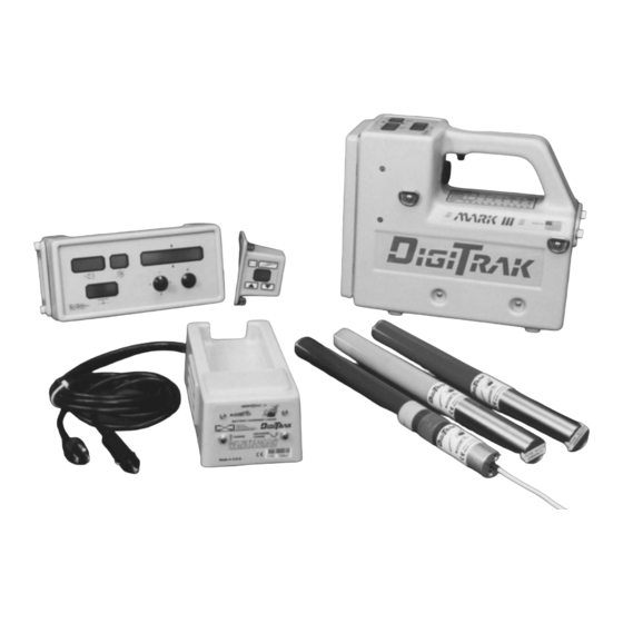
- Page 1 Mark III Directional Drilling Locating System Operator’s Manual IGITAL ONTROL NCORPORATED DCI Headquarters DCI Europe DCI India DCI China DCI Australia 19625 62 Ave. S., Suite B-103 Kurmainzer Strasse 56 SCO # 259, Sector 44-C USA Excalibre 2/9 Frinton Street...
- Page 2 Before utilizing any DCI product, the user should determine the suitability of the product for its intended use. All statements herein refer to DCI products as delivered by DCI and do not apply to any user customizations not authorized by DCI nor to any third-party products. Nothing herein shall constitute any warranty by DCI nor will anything herein be deemed to modify the terms of DCI’s...
-
Page 3: Table Of Contents
® IGITAL ONTROL NCORPORATED Table of Contents SAFETY PRECAUTIONS AND WARNINGS .................. vi INTRODUCTION ..........................1 Basic DigiTrak Equipment ....................1 Basic DigiTrak Operation.....................2 Technical Support........................3 RECEIVER ............................5 Display Window Icons ......................6 On/Off ..........................7 Receiving the Transmitter’s Signals ..................8 Clicking vs. Holding the Trigger ..................8 Changing the Receiver’s Channel Setting................9 Changing the Depth Measurement Units (English vs. - Page 4 ® IGITAL ONTROL NCORPORATED Table of Contents (Cont.) REMOTE DISPLAY SYSTEM ......................25 On/Off and Setting the Channel ..................26 Transmitter Temperature and Battery Status ..............26 Remote Steering........................27 Finding Firmware Version....................28 DataLog Capability ......................28 BATTERY CHARGER ........................29 Charging a Battery......................30 Conditioning a Battery in the Charger ................31 Conditioning a Battery Manually..................31 Indicator Lights and Meanings...................31 SYSTEM OPERATING INSTRUCTIONS ..................33...
- Page 5 ® IGITAL ONTROL NCORPORATED Table of Contents (Cont.) LOCATING (Cont.) Calculating Depth Based on Distance Between FNLP & RNLP ........52 Running Off Pitch or Calculating Depth from Pitch ............53 Transmitter’s Signal Shape ....................54 Antennae Configuration.....................54 Signal Reception .......................54 Front and Rear Negative Locate Points ................55 Positive Locate Line Above Transmitter................55 CABLE TRANSMITTER SYSTEM ....................57 Power Supply........................59...
-
Page 6: Safety Precautions And Warnings
® IGITAL ONTROL NCORPORATED Safety Precautions and Warnings Important Note: All operators must read and understand the following Safety Precautions and Warnings before using the DigiTrak Locating System. Serious injury and death can result if underground drilling equipment makes contact with an underground utility such as a high-voltage electrical cable or a natural gas line. - Page 7 DigiTrak System properly to obtain accurate depth, pitch, roll, and locate points. If you have any questions about the operation of the DigiTrak System, please call DCI’s Customer Service Department at 425-251-0559 or 800-288-3610 between the hours of 6:00 a.m. and 6:00 p.m.
- Page 8 ® IGITAL ONTROL NCORPORATED Dear Customer: We would like to thank you for choosing the DigiTrak Locating System. We are proud of the equipment that we have been designing and building in Washington State since 1990. We believe strongly in providing a unique, high-quality product and standing behind it with superior customer service and training.
-
Page 9: Introduction
Mark III Receiver is the version identified; older versions are not specified on the receiver. If you need to know what version you have, you can contact DCI. Transmitter – Also referred to as a sonde, beacon, or probe, the DigiTrak Transmitter is placed in the drill tool/housing to send information to the receiver. -
Page 10: Basic Digitrak Operation
Calibration is not re- quired every day; however, DCI recommends you verify the calibration by checking the distance readings (bottom window) with a tape measure prior to the beginning of each drilling run. (see “Calibrating the Receiver”... -
Page 11: Technical Support
We have listed many of the common problems and solutions in the Trouble- shooting Section in this manual. If you cannot find the answers you need there, then please call DCI for assistance. (see “Technical Support” below) - Page 12 ® Introduction Notes 3-3000-00b-F ® DigiTrak Mark III Operator’s Manual...
-
Page 13: Receiver
® IGITAL ONTROL NCORPORATED Receiver Trigger Handle Speaker Display Windows Temperature & Distance Conversion Chart Depth/Locating Battery Antenna Screws Compartment Back Panel Front Panel Pitch/Roll Antenna Screws DigiTrak Receiver – Side View The DigiTrak Receiver is a hand-held unit used for loca- Trigger Up Temperature ting and tracking the transmitter. -
Page 14: Display Window Icons
Showing Condensed Instructions Showing Identification Information The front panel of the receiver has condensed instructions for quick field reference and DCI’s phone numbers for troubleshooting assistance. There is also a sticker under the handle for temperature and dis- tance conversions. The serial number is located on the back panel of the unit below the battery compart- ment;... -
Page 15: On/Off
New versions of the firmware are available for upgrading older systems, but the firmware must be upgraded by DCI. To determine the firmware version installed in your equipment, see “Finding Firmware Version” in the Receiver and Remote Display Sections. -
Page 16: Receiving The Transmitter's Signals
® Receiver The depth measurement units (centimeters or inches) and remote channel setting can be changed only during start-up (see “Changing Depth Measurement Units” and “Changing the Channel Setting” below). After the start-up process, the windows will display pitch, roll, and distance if there is an active transmitter within range (see Tracking Mode display below). -
Page 17: Changing The Receiver's Channel Setting
® Receiver For receivers that have pre-5.0 series firmware, the bottom window will continue to display the receiver’s distance from the transmitter in the bottom window, not the predicted depth. (For more information, see “5.0 Series Firmware Functions” in this section or see the Locating Section.) Any time the trigger is clicked (pushed in and released in less than ½... -
Page 18: Changing The Depth Measurement Units (English Vs. Metric)
This mode will remain the same until changed and is not affected by battery replacement. Older receivers that have not been upgraded require a different method for changing the depth measure- ment units. Contact DCI Customer Service (425-251-0559 or 800-288-3610) for assistance. Battery Status Display for Receiver and Transmitter... -
Page 19: Warning Tones For Transmitter Overheat
® Receiver Warning Tones for Transmitter Overheat Beginning with firmware version 3.76, the DigiTrak Receiver will emit a series of increasing warning tones to signal transmitter overheating as follows: Temperature Range Warning Signal No audio or visual warnings. 14°C and below 15°C to 35°C One double tone with every 4°C increase in temperature. -
Page 20: Setting The Ultrasonic Distance Or Height-Above-Ground Measurement
® Receiver Following are some general points regarding the ultrasonic function: The ultrasonic function in the receiver is independent of the transmitter receiving functions. A single click to activate the ultrasonic function can be used an unlimited number of times without affecting the receiver’s calibration. -
Page 21: Calibrating The Receiver
The signal strength must Housing) be at least 250 points for proper calibration. If your reading is less than 250, the transmitter may be Receiver malfunctioning, and you should call Transmitter Centerline DCI. Determining 1-Point Calibration Signal ® DigiTrak Mark III Operator’s Manual... -
Page 22: 2-Point Calibration Procedure
® Receiver 4. Click the trigger one time. 5. The receiver will beep. During the beep, pull in the trigger and hold it. 6. Continue to hold the trigger and watch the countdown (from 5 to 0) displayed in the bottom window. This countdown is accompanied by a chirping sound. - Page 23 ® Receiver 5. During the tone, click the trigger again and continue to hold the receiver level and steady. You will then hear 2 beeps followed by a long 6-second tone, indicating that the first calibration point is found. 6. During the 6-second tone, raise the receiver straight up, keeping it level and in the same plane above the transmitter, as high as you comfortably can.
-
Page 24: Calibrating With Transmitter Underground At Shallow Depth (<10 Ft)
® Receiver Calibrating with Transmitter Underground at Shallow Depth (< 10 feet) Should recalibration be necessary when the transmitter is below ground at depths less than 10 ft (3 m), it is possible to conduct a modified 1-point calibration procedure. This requires knowing the signal strength of the transmitter in the housing at 10 ft. -
Page 25: Finding Firmware Version
It is possible to determine the firmware version in the receiver. This information is necessary to complete troubleshooting diagnostics with DCI Customer Service by telephone. At start-up the firmware version is displayed briefly in the top left window. If you do not see the firmware version, it is likely that you have an older receiver. -
Page 26: Procedure For Observing The Predicted Depth
® Receiver Procedure for Observing the Predicted Depth When the receiver (with 5.0 firmware) is at the FNLP and held level with the trigger in, the bottom window will rapidly flash the predicted depth number accompanied by a solidly lit squiggle (“~”); the predicted depth information is also displayed in the bottom window on the remote display. -
Page 27: Transmitter
DigiTrak Transmitter Specifications table at the end of this section. NOTE: The range of any transmitter with any DCI receiver is dependent upon the amount of inter- ference at a job site. The range decreases as interference increases. -
Page 28: Batteries
Batteries All DCI transmitters (except the cable transmitter) are powered by C-cell alkaline batteries (see Trans- mitter Specifications at the end of this section). The long-range transmitters, including the sensitive-pitch transmitters, have a 4 C-cell option for longer bores. -
Page 29: Sleep Mode (Automatic Shutoff)
® Transmitter The temp dot should be white if the transmitter has not been exposed to excessive heat. If the temp dot is silver or gray, it indicates the transmitter has been exposed to heat but not in excess of the speci- fications. - Page 30 The width of the slots may be as narrow as necessary to maintain housing strength. (Drawings showing the proper slot width, length, and positioning can be obtained by request from DCI.) These slots must not have any filler material containing metal particles, e.g., liquid steel.
-
Page 31: Locating The Transmitter
The sensitive-pitch transmitters are designed for gravity sewer installations where pitch must be known in increments smaller than 1%. DCI’s sensitive-pitch transmitters operate exactly the same as regular-pitch (1%) transmitters except that the pitch is measured and displayed in one-tenth percent (0.1%) increments. -
Page 32: Serial Numbers
All transmitters are identified by a serial number stamped in the metal battery compartment near the plastic/stainless steel contact. NOTE: When calling DCI Customer Service be prepared to supply the serial number. Specifications The specifications given below assume the use of the latest model (Mark III) of the DigiTrak Receiver. All Mark III Transmitters operate at a frequency of approximately 33 kHz. -
Page 33: Remote Display System
All receivers can be upgraded to remote capability by DCI. The maximum separation between the receiver and the remote display can range up to about 4000 ft (1220 m) depending upon interference and topographic features. -
Page 34: On/Off And Setting The Channel
For more information on transmitter temperature display intervals, see firmware update information on DCI’s web page located at www.digitrak.com. To determine the remote display unit’s firmware version, see “Finding Firmware Version” below and, for the receiver, see “Finding Firmware Version” in the Receiver Section. -
Page 35: Remote Steering
® Remote Display Remote Steering Receiver Placed on Side (Drill Remote steering is used to cross streams and Path Is Aligned roadways or other inaccessible areas when it is with Target Point not possible to walk over the transmitter. To on Front Panel) initiate the remote steering capability, the Target Point... -
Page 36: Finding Firmware Version
DataLog module attachment. The DataLog module also has a speaker, so the drill operator hears the transmitter temperature increase tones and logging tones. Call DCI if you are interested in obtaining more information on the DataLog Mapping System. -
Page 37: Battery Charger
® IGITAL ONTROL NCORPORATED Battery Charger DigiTrak Battery Pack Unexposed Terminal -- Do Not Expose -- DC Power Cord AC Power Cord Negative Terminal Control Positive Panel Terminal DigiTrak Battery Charger Both the DigiTrak Receiver and the Remote Display use a DigiTrak rechargeable NiCad battery pack that is provided with the system together with a DigiTrak Battery Charger. -
Page 38: Charging A Battery
® Battery Charger Only two terminals are exposed on the DCI NiCad battery pack, although a third terminal appears to be available. If the third terminal accidentally becomes exposed, do not try to charge the battery pack or you may damage the battery charger. Such a battery can also damage the remote display or receiver. A damaged battery pack will require replacement. -
Page 39: Conditioning A Battery In The Charger
4. When the battery has reached full charge, the green light will illuminate indicating a fully charged battery is ready. Conditioning a Battery Manually To condition a DCI battery pack, you simply need a low-wattage 12V light (such as a small automotive side light or an interior light bulb) - Page 40 ® Battery Charger Notes 3-3000-00f-F ® DigiTrak Mark III Operator’s Manual...
-
Page 41: System Operating Instructions
Placing a cold beverage can on the display window will confirm the presence of moisture if there is a ring of droplets after the can is removed. Contact DCI at 425-251-0559 or 800-288-3610 for field “drying” technique. ®... -
Page 42: Optimal Operating Temperatures
Store the DigiTrak equipment in cases, away from heat, cold, and moisture. Perform tests to confirm proper operations. Do not disassemble or attempt to repair DigiTrak locating equipment. Contact DCI at 425-251-0559 or 800-288-3610 or visit our web site at www.digitrak.com to stay current with the latest innovations. -
Page 43: Signal Interference
Active interference is also known as electrical interference or noise and can have varying effects upon the DigiTrak locating equipment. Most electrical devices emit signals. Because DCI receivers have two types of antennas in them (depth and roll/pitch), it is possible to have interference that affects one or both signals. -
Page 44: Suggestions For Dealing With Interference
® Signal Interference There are two steps to the electrical interference/background noise check. The first step takes one person; the second step requires two people. 1. With the transmitter off, test the amount of noise the receiver hears by holding in the trigger and walking the borepath from the launch to the exit location. -
Page 45: Operational Tests
5. An error code of “001” indicates high background noise; move to an interference-free area and con- duct the self-test again. For assistance with troubleshooting an error code call DCI. Receiver Balance Check If the receiver appears to be exhibiting a consistent left or right error, it is possible that the antennas in the receiver are out of balance. -
Page 46: Receiver Gain Test
Walk back toward the axis line from this opposite side and find the location where the “+” changes to a “–”. 5. These two locations should be in the same place and lie on the axis line. If not, call DCI for assistance. - Page 47 If not, check for interference, verify the transmitter’s signal strength, or call DCI Customer Service at 425-251-0559 or 800-288-3610 for assistance in determining the source of the problem.
-
Page 48: Transmitter Salt Water Range Test
® Operational Tests Battery Life – Verify the housing slots (windows) are properly aligned over the transmitter’s antenna. If the battery life of a transmitter seems to be shorter than that noted in the specifications provided in the Transmitter Section, it could be due to battery arcing, which can occur in hard drilling conditions. transmitter batteries arc when they bounce/slam into each other, losing contact intermittently. -
Page 49: Transmitter Battery Tests
® Operational Tests Transmitter Battery Tests The design of the windows/slots in a housing can greatly affect the transmitter’s battery life, especially on the red long-range DX Transmitters. The windows must be a minimum of 8 inches (20 cm) long and line up longitudinally along the drill housing, directly above the center of the transmitter. - Page 50 ® Operational Tests Notes 3-3000-00i-F ® DigiTrak Mark III Operator’s Manual...
-
Page 51: Locating
® IGITAL ONTROL NCORPORATED Locating Locating Mode Signal Transmitter Strength Temperature To locate the transmitter the receiver’s trigger must be held in. This is referred to as the “locating mode”. When the trigger is held in, the top left window will stop dis- playing pitch with the flashing pitch/roll up- Plus (+) Indicator... -
Page 52: Handling The Receiver
® Locating Handling the Receiver For the most accurate locating, the receiver must be held level and parallel to the transmitter. The receiver Receiver parallel to Transmitter and facing in opposite direction can be held so that it faces in the same direction as the transmitter or in the opposite direction (see sketch). -
Page 53: Using Plus/Minus Indicators For Locating
® Locating In summary, the three locations mentioned above are as follows: the rear negative locate point (RNLP), behind the transmitter; the positive locate line, above the transmitter; and the front negative locate point (FNLP), ahead of the transmitter. The RNLP and the FNLP show the position and lateral orientation of the transmitter. -
Page 54: Finding The Positive Locate Line (Pll)
® Locating 2. To determine the lateral and therefore the actual location of the RNLP, turn toward the left so that the receiver is perpendicular (90°) to the drill string and move the receiver forward. Again, move the receiver slightly forward and backward until pinpointing the location where the “+/–”... -
Page 55: Finding The Front Negative Locate Point (Fnlp)
® Locating Finding the Front Negative Locate Point (FNLP) 4. At the PLL, con- tinue walking away from the drill with Plus the trigger held in; Changes the signal strength to Minus will decrease. When the “+” sign flips to a “–” sign, Surface of this is the FNLP. -
Page 56: Finding The Transmitter And Its Depth
® Locating Finding the Transmitter and Its Depth 7. While standing on the FNLP facing the drill, it is possible to “sight in” or align the FNLP with the RNLP. This axis line is at a 90° angle (perpendicular) to the PLL. Where this axis line crosses the PLL is where the transmitter will be found, below ground surface. -
Page 57: Locating The Transmitter From The Front
® Locating Locating the Transmitter from the Front The transmitter’s three locations can be determined in a similar manner as described above starting in front of the transmitter while facing the drill. Start at a location well ahead of the transmitter and hold in the trigger while facing the drill. A “+” sign should appear in the top left window (along with the signal strength). -
Page 58: Locating On The Fly
® Locating Locating on the Fly Once you are comfortable finding the transmitter’s three locating points (FNLP, RNLP, and PLL) it is time to increase your speed at locating. Hopefully this will directly affect your productivity! 1. Mark the position of the FNLP and pace out the distance of the next drill rod (this distance will vary depending upon the pitch of the transmitter and the topography). -
Page 59: Splitting The Front And Rear Negative Locate Points
® Locating 4. Step further to the side of the transmitter and again find the point where the “–” sign changes to a “+” (Point 2). 5. Repeat this procedure to find the third location (Point 3). When all three of these points are lined up, they confirm the location of the PLL, from which the heading of the transmitter can be determined, because the PLL is at a 90°... -
Page 60: Calculating Depth Based On Distance Between Fnlp & Rnlp
® Locating 7. Repeat steps 2 through 6 until the “+/–” signs flip from one to the other over a very small area. This is either the FNLP or the RNLP. To find the other locate point, walk in the assumed direction of drilling. If the signal strength increases you are at the RNLP;... -
Page 61: Running Off Pitch Or Calculating Depth From Pitch
® Locating Running off Pitch or Calculating Depth from Pitch The transmitter’s depth can be estimated by using the pitch information. Use the following procedure to estimate the depth based on the pitch, starting with the first rod. 1. At the point the drill head penetrates the surface of the ground to the middle of the transmitter’s slots (entry point), measure the amount of rod left on the rack (from the make-up/breakout clamps to the top of the rod). -
Page 62: Transmitter's Signal Shape
® Locating Transmitter’s Signal Shape It is important to understand some fundamental con- cepts about the transmitter’s electromagnetic signal and the way the receiver’s antennas read or receive this signal. The shape of the transmitter’s signal field is elliptical. This elliptically shaped field combined with the DigiTrak Receiver’s unique “X”... -
Page 63: Front And Rear Negative Locate Points
® Locating Field Strength: Field Strength: 100% 100% Parallel Field Lines and Antenna Perpendicular Field Lines and Antenna Orientation of Field Lines with Respect to Antennas Front and Rear Negative Locate Points If the field line is vertical with respect to the antennas, each antenna will read 50% of the signal (figure). - Page 64 ® Locating Notes 3-3000-00j-F ® DigiTrak Mark III Operator’s Manual...
-
Page 65: Cable Transmitter System
® IGITAL ONTROL NCORPORATED Cable Transmitter System Power Supply Remote Display Cable Transmitters Extraction/Insertion Tool DigiTrak Cable Transmitter System The DigiTrak Cable Transmitter System is designed specifically for the following applications: Borepaths with depths in excess of 50 ft (15 m). Borepaths with lengths that require several days to drill. - Page 66 Items such as compression fittings, 10-gauge stranded copper wire, heat shrink, butt splices, and slip-ring assemblies are not available from DCI. Drill manufacturers will have information on slip-ring assemblies, mud swivels, and compres- sion fittings. Electrical supply houses will carry the rest of the equipment needed for the Cable Trans- mitter System.
-
Page 67: Power Supply
Cable Transmitter Power Supply The Cable Transmitter Power Supply plugs into the remote display where a regular DCI battery pack is normally placed. The power supply has three wires extending from it. The green and black wires should be connected to a DC power source (green is positive, black is negative). The white wire is connected to the cable transmitter (see sketch later in this section called “Connecting Cable Transmitter to Power... -
Page 68: Cable Transmitter
® Cable Transmitter Cable Transmitter The cable transmitter has the same general features and capabilities as the other DigiTrak Transmitters but with increased depth range. The dimensions of the cable transmitter are the same as those of the 2- cell DigiTrak Transmitters (DT, DX, and DXP). However, there is also a power/signal cable extending from the rear metal grounding cap. -
Page 69: Remote Display With Cable Transmitter Capability
® Cable Transmitter Temperature information can be accessed manually by turning off and then on the cable-ready remote display. Upon supplying power, the cable transmitter will begin transmitting data. There is no sleep mode; therefore, the power supply must be turned off manually at the end of the day. -
Page 70: Viewing The Cable System Battery Status
100%, 19V as 50%, 12V as 25%, 9V as 0%. When a standard DCI battery pack is installed into the remote display, rather than the Cable Transmitter Power Supply, it will automatically switch from the cable transmitter mode. Pitch, roll, temperature, and battery status will again be received by telemetry from the DigiTrak Receiver. -
Page 71: Troubleshooting
Interference. receiver. Background Noise Check” Low battery in receiver. in Signal Interference Moisture inside the equipment. Call DCI Section for information about field methods for Remote Display Section “drying” out the equipment. Moisture can be caused by condensation which occurs... - Page 72 ® Troubleshooting Problem/Concern Causes/Solutions Section to Consult Remote display has dashes Interference is interrupting the signal from “Electrical Interference/ across windows. the receiver. Background Noise Check” (Continued) in Signal Interference Line of sight between receiver and remote Section display may be obstructed (by such things as buildings, hills, or dense vegetation).
- Page 73 The antennas can be balanced by using the locate points. performing a diagnostic procedure over the phone with DCI customer service personnel or by sending your receiver to DCI for testing/repair. All windows are blank. Receiver has shut off to conserve battery “1-Point Calibration...
- Page 74 ® Troubleshooting Problem/Concern Causes/Solutions Section to Consult Minus sign (“–”) in bottom Receiver is set on ground for depth “Ultrasonic Function” in window. reading, particularly at shallow depths, and Receiver Section the ultrasonics are not reset. Reset the “Calibrating the Receiver” ultrasonics.
- Page 75 (upside down) and fling out the liquid. Repeat two more times and allow to dry for about 15 minutes. If you still cannot get the ultrasonic function to perform properly, call DCI customer service at 425-251-0559 or 800- 288-3610 for assistance. ®...
- Page 76 ® Troubleshooting Notes 3-3000-00l-F ® DigiTrak Mark III Operator’s Manual...
-
Page 77: Glossary
® IGITAL ONTROL NCORPORATED Glossary Active Transmitter A transmitter that has batteries installed or a cable transmitter that is hooked up to power. Battery Charger Used to charge and condition (discharge) the DigiTrak batteries. May be used with AC or DC sources and is easily adapted for worldwide usage. - Page 78 The angle or inclination of the transmitter relative to the horizontal displayed in percent (%) slope (rise divided by run). DCI transmitters can measure and display pitch in both 1% and 0.1% increments. Positive Locate Line (PLL) = Line Above Transmitter that Runs Perpendicular to the Transmitter This location in conjunction with the FNLP and/or RNLP determines the position of the transmitter be- low ground.
- Page 79 ® Glossary Remote Display A device at or near the drill rig used to display the transmitter’s information communicated from the receiver. This device can be used for remote steering when walkover locating is not possible. Roll The rotation about the longitudinal axis of the transmitter. Set the Ultrasonics To set the ultrasonics, click the trigger once and observe the bottom window.
- Page 80 ® Glossary Ultrasonic Distance = Ultrasonic Measurement = Height-Above-Ground Measurement The receiver’s height above the ground, which is displayed in the bottom window for 2 seconds after the trigger is clicked. The ultrasonic measurement is used to accommodate the different heights of drillers.
-
Page 81: Appendix
® IGITAL ONTROL NCORPORATED Appendix The information and tables contained in this appendix provide further assistance for confirming the posi- tion of the Transmitter. The following information is provided: Depth Increase in Inches per 10-foot Rod Percent of Grade to Degree Conversions (1% Pitch Transmitters) Percent of Grade to Degree Conversions (0.1% Pitch Transmitters or Sensitive Pitch) Degree to Percent of Grade Conversions (1% Pitch Transmitters) Degree to Percent of Grade Conversions (0.1% Pitch Transmitters) -
Page 82: Depth Increase In Inches Per 10-Foot Rod
® Appendix Depth Increase in Inches per 10-foot Rod Percent Depth Increase Percent Depth Increase ® DigiTrak Mark III Operator’s Manual... -
Page 83: Percent Of Grade To Degree Conversions (1% Pitch Transmitters)
® Appendix Percent of Grade to Degree Conversions (1% Pitch Transmitters) Percent Degree Percent Degree Percent Degree Percent Degree 14.6 27.0 37.2 15.1 27.5 37.6 15.6 27.9 38.0 16.2 28.4 38.3 16.7 28.8 38.7 17.2 29.2 39.0 17.7 29.7 39.4 18.3 30.1 39.7... -
Page 84: Percent Of Grade To Degree Conversions (0.1% Pitch Transmitters Or Sensitive Pitch)
® Appendix Percent of Grade to Degree Conversions (0.1% Pitch Transmitters or Sensitive Pitch) Percent Degree Percent Degree Percent Degree Percent Degree ® DigiTrak Mark III Operator’s Manual... -
Page 85: Degree To Percent Of Grade Conversions (1% Pitch Transmitters)
® Appendix Degree to Percent of Grade Conversions (1% Pitch Transmitters) Degrees Percent Degrees Percent 42.4 44.5 46.6 48.8 51.0 53.2 10.5 55.4 12.3 57.7 14.1 60.1 15.8 62.5 17.6 64.9 19.4 67.5 21.3 70.0 23.1 72.7 24.9 75.4 26.8 78.1 28.7 81.0... -
Page 86: Degree To Percent Of Grade Conversions (0.1% Pitch Transmitters)
® Appendix Degree to Percent of Grade Conversions (0.1% Pitch Transmitters) Degrees Percent Degrees Percent 10.0 ® DigiTrak Mark III Operator’s Manual... -
Page 87: Calculating Depth Based On Distance Between Fnlp And Rnlp
® Appendix Calculating Depth Based on Distance Between FNLP and RNLP It is possible to estimate the transmitter’s depth should the information displayed in the depth/distance window become unreliable. This is only possible if the pitch and negative locate points are reliable and the ground surface is level. - Page 88 ® Appendix Notes 3-3000-00n-F ® DigiTrak Mark III Operator’s Manual...
-
Page 89: Remote Telemetry License
19625 62nd Ave. S., Suite B-103 Kent, Washington 98032 USA 425-251-0559 or 800-288-3610 Fax 253-395-2800 www.digitrak.com (Web Site) DCI@digital-control.com (E-mail) REMOTE TELEMETRY LICENSE The attached license is required by the United States Federal Communications Commission (“FCC”) for operation of the ®... - Page 90 Page 2 of 2 3-3000-00o-F...
-
Page 91: Limited Warranty
DCI Product. The Warranty Period shall begin from the later of: (i) the date of shipment of the DCI Product from DCI, or (ii) the date of shipment (or other delivery) of the DCI Product from an Authorized DCI Dealer to User. - Page 92 If you authorize DCI to service or repair the DCI Product, the work will be promptly performed and the DCI Product will be shipped to you. You will be billed for any costs for testing, repairs and adjustments not covered by the Limited Warranty and for shipping costs.
Need help?
Do you have a question about the DigiTrak Mark III and is the answer not in the manual?
Questions and answers