Siemens SIMATIC PC Adapter USB Manual
Hide thumbs
Also See for SIMATIC PC Adapter USB:
- Quick reference manual (28 pages) ,
- Manual (58 pages) ,
- Operating instructions manual (27 pages)
Table of Contents
Advertisement
s
SIMATIC
PC Adapter USB
Manual
10/2007
A5E01134250-01
Preface,
Contents
Properties of the
PC Adapter USB
Package Components
Requirements for Operation
Hardware Design of the
PC Adapter USB
Working with the
PC Adapter USB
PC Adapter USB on the
MPI/DP Network
Firmware Update
Error Diagnostics
Technical Data
Appendix
Index
1
2
3
4
5
6
7
8
9
10
Advertisement
Table of Contents

Related Manuals for Siemens SIMATIC PC Adapter USB


Summary of Contents for Siemens SIMATIC PC Adapter USB
- Page 1 Preface, Contents Properties of the PC Adapter USB SIMATIC Package Components Requirements for Operation PC Adapter USB Hardware Design of the PC Adapter USB Working with the PC Adapter USB Manual PC Adapter USB on the MPI/DP Network Firmware Update Error Diagnostics Technical Data Appendix...
- Page 2 Trademarks All names identified by ® are registered trademarks of the Siemens AG. The remaining trademarks in this publication may be trademarks whose use by third parties for their own purposes could violate the rights of the owner.
- Page 3 Preface Purpose of the Manual This manual gives you a complete overview of PC Adapter USB. It guides you when installing and commissioning the software and hardware. It also describes the operation and hardware installation requirements, as well as, the connection of the Adapter to MPI/DP networks.
- Page 4 PC Adapter USB is compliant with requirements of the AS/NZS 3548 (Australian and New Zeeland) standard. Further Support If you have any technical questions, please get in touch with your Siemens representative or agent responsible. You will find your contact person at: http://www.siemens.com/automation/partner...
- Page 5 Preface Technical Support You can get Technical Support for all A&D products • Via the Web formula for the Support Request http://www.siemens.de/automation/support-request • Phone: + 49 180 5050 222 • Fax: + 49 180 5050 223 You can find more information on our Technical Support on the Internet under http://www.siemens.de/automation/service...
- Page 6 Preface PC Adapter USB A5E01134250-01...
-
Page 7: Table Of Contents
Contents Properties of the PC Adapter USB Function ......................1-1 Performance specifications................1-2 Package Components Requirements for Operation Software requirements..................3-1 Hardware requirements ..................3-1 Hardware Design of the PC Adapter USB Connections...................... 4-1 LEDs on the PC Adapter USB................4-2 Power supply .................... - Page 8 Contents PC Adapter USB viii A5E01134250-01...
-
Page 9: Properties Of The Pc Adapter Usb
(hibernate mode). Function The SIMATIC PC Adapter USB connects a PC to the MPI/DP interface of an S7/M7/C7 system via USB. A slot is not required in the PC, which means that the adapter can also be used for non-expandable PCs such as notebooks. -
Page 10: Performance Specifications
Properties of the PC Adapter USB Performance specifications The PC Adapter USB can be used on MPI and PROFIBUS networks. Starting at firmware V1.1, the PC Adapter USB can also be operated on homogeneous PPI networks. The following table shows the transmission rates and network types supported by the PC Adapter USB. -
Page 11: Package Components
MPI cable (0.3 m) A5E00164946 You can forward your spare parts orders to your local Siemens partner. Supplies (not included in the PC Adapter USB) To operate the PC Adapter USB to MPI/DP interfaces which do not have a 24V supply voltage, you can order an external power supply (order number: 6ES7 972-0CA00-0XA0). - Page 12 Package Components PC Adapter USB A5E01134250-01...
-
Page 13: Requirements For Operation
Requirements for Operation Software requirements One of the following operating systems must be installed on the PC in order to be able to operate the SIMATIC PC Adapter USB: • Windows 2000 • Windows XP Professional • Windows XP Home •... - Page 14 Requirements for Operation PC Adapter USB A5E01134250-01...
-
Page 15: Hardware Design Of The Pc Adapter Usb
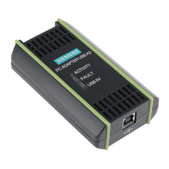
Hardware Design of the PC Adapter USB Connections Connections or displays on the PC Adapter USB: USB interface LEDs: Power MPI/DP interface PC Adapter USB A5E01134250-01... -
Page 16: Leds On The Pc Adapter Usb
Hardware Design of the PC Adapter USB LEDs on the PC Adapter USB The LEDs on the PC Adapter USB indicate the following: Name Color Meaning green Lights up when the PC Adapter USB is connected to the USB and the operating system of your PC is in normal operating mode. -
Page 17: Power Supply
Hardware Design of the PC Adapter USB Power supply The PC Adapter USB is supplied with power by the automation system via the MPI cable or alternatively via the external power supply (see Section 2) included in the delivery. It requires 24 V (see the technical data). Caution Always connect the PC Adapter USB to power supplies with limited power or NEC Class 2. - Page 18 Hardware Design of the PC Adapter USB Shield M24V LTG_B RTSAS P24V LTG_A Shield 9-pin subminiature D 9-pin subminiature D Fig. 2: MPI cable (0.3 m) RTSPG LTG_A LTG_B RTSAS Electronics P24V +3,15V +1,95V M24V Shield PC potential area AS potential area Fig.
-
Page 19: Mpi/Dp Interface
Hardware Design of the PC Adapter USB MPI/DP interface Pin assignment Pin assignment of the MPI/DP interface: Description of signals Pin no. Short name Meaning Input / Output Not connected – M24V Zero volt of the 24 V power supply, Input provided by the electronic DC/DC circuit of the adapter (AS potential range) -
Page 20: Usb Interface
Hardware Design of the PC Adapter USB USB interface Interface pin assignments Top view of the USB socket: Description of signals Pin no. Signal Power supply -Data - Differential signal + Data + Differential signal Ground Ground Caution Operating several USB devices on your PC may effect the data transmission rates. To obtain optimum communication performance with the automation system, disconnect USB devices that are not required. -
Page 21: Working With The Pc Adapter Usb
Siemens. The product will function correctly and safely only it is transported, stored, set up, and installed as intended, and operated and maintained with care. -
Page 22: Configuring The Pg / Pc Interface
Working with the PC Adapter USB Configuring the PG / PC interface You are prompted to configure the PG / PC interface during setup. 1. Check the PG / PC interface dialog box for the following interface settings. The following items should be available in the selection list: PC Adapter (Auto) (only when STEP 7 is installed) PC Adapter (MPI) PC Adapter (PPI) (only if STEP 7-Micro/Win has been installed) -
Page 23: Connecting The Pc Adapter Usb
"PG socket“ of a PROFIBUS connector (SINEC L2 bus connector). You do not need to change the settings of the terminating resistors. Caution Do not connect the SIMATIC PC Adapter USB to the automation system with any other cable than the supplied MPI cable. PC Adapter USB... - Page 24 Working with the PC Adapter USB PC Adapter USB A5E01134250-01...
-
Page 25: Pc Adapter Usb On The Mpi/Dp Network
PC Adapter USB on the MPI/DP Network General A maximum of 32 nodes can be connected to an MPI/DP network segment. The total cable length may not exceed 50 meters. Several network segments can be connected together using RS485 repeaters, thus allowing a maximum number of 127 network nodes. -
Page 26: Use In A Networked System
PC Adapter USB on the MPI/DP Network Use in a networked system The following illustration shows the connection in a networked S7 system (MPI/DP network containing 2 or more network nodes). Adapter PROFIBUS bus cable Bus connector with PG socket PROFIBUS bus connector Once you have completed the installation and configuration of the PG / PC interface, you can communicate with the PLC using your SIMATIC software... -
Page 27: Firmware Update
How to update the firmware: • Download the latest firmware and the firmware update utility from the Internet: http://www.siemens.com/automation/service&support • Search the product support area for the term "PC Adapter USB“. • Download the self-extracting EXE file containing the available firmware and the firmware update utility to your PC. - Page 28 Firmware Update PC Adapter USB A5E01134250-01...
-
Page 29: Error Diagnostics
Error Diagnostics The information in the following section offers support to help you locate and perhaps correct common errors by yourself. Error / cause To avoid or correct errors The power LED is not lit • • MPI cable not connected Connect the MPI cable •... - Page 30 Error Diagnostics PC Adapter USB A5E01134250-01...
-
Page 31: Technical Data
Technical Data PC Adapter USB Order no. 6ES7972-0CB20-0XA0 Dimensions Approx. 105 x 58 x 26 mm Weight Approx. 250 g Interfaces to S7 / M7 / C7 RS485 (max. 1.5 Mbps) to PC (12 Mbps) Power supply 24 V DC (SELV) (18V.. 30 V DC) (via MPI interface) Power consumption 50 mA (typically) / 100 mA (max.) - Page 32 Technical Data PC Adapter USB Mechanical ambient conditions Vibration Tested according to DIN IEC 60068-2-6 Operation 10 to 58 Hz: amplitude 0.075 mm, 58 to 500 Hz: acceleration 9.8 m/s Storage / shipping 5 to 9 Hz: amplitude 3.5 mm, 9 to 500 Hz: acceleration 9.8 m/s Shockproof Tested according to DIN IEC 60068-2-27/29...
-
Page 33: Appendix
EN 61000-6-2: 2001 Declaration of Conformity The EC declarations of conformity and the documentation relating to this are available to the authorities concerned, according to the above EC directive, from: Siemens AG Automation and Drives A&D AS RD 4 PO Box 1963 D–92209 Amberg, Germany... - Page 34 Appendix Observing the installation guidelines The installation guidelines and notes on safety given in the manual must be observed at startup and during operation. Connecting I/O devices Noise immunity when connected to industrial standard PC conforms with the requirements of EN 61000-6-2:2001. PC Adapter USB 10-2 A5E01134250-01...
-
Page 35: Certification For The Usa, Canada And Australia
Appendix 10.2 Certification for the USA, Canada and Australia One of the following markings on a device is indicative of the corresponding approval: Underwriters Laboratories (UL) according to the UL 60950 standard, and Canadian standard C22.2 No. 60950 (I.T.E) or to UL508 and C22.2 No. 142 (IND.CONT.EQ) UL Recognition Mark Australia and New Zealand... - Page 36 Appendix PC Adapter USB 10-4 A5E01134250-01...
-
Page 37: Index
Index MPI cable 2-1 MPI/DP interface 4-5 MPI/DP network 6-1 Busprofile 1-2 Operating state LEDs 4-2 Compatibility 1-1 Configuration with the PC Adapter USB 1-1 Connecting to the PC 5-3 Connecting to the PLC 5-3 Package components 2-1 Connections 4-1 Performance specifications 1-2 POWER 4-2 Power supply 4-3... - Page 38 Index PC Adapter USB A5E01134250-01...
Need help?
Do you have a question about the SIMATIC PC Adapter USB and is the answer not in the manual?
Questions and answers