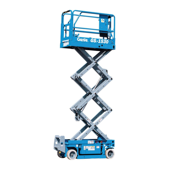
Genie GS-1930 Service Manual
Before serial number 17408
Hide thumbs
Also See for GS-1930:
- Operator's manual (86 pages) ,
- Service and repair manual (335 pages) ,
- Service manual (298 pages)

Related Manuals for Genie GS-1930


Summary of Contents for Genie GS-1930
- Page 1 ® Technical Publications GS-1530 GS-1930 Service Manual (before serial number 17408) First Edition, Third Printing Rev C2 Part No. 39528...
-
Page 2: Introduction
"Genie" is a registered trademark Readers are encouraged to notify Genie of errors of Genie Industries in the U.S.A. and many other and send in suggestions for improvement. All countries. "GS" is a trademark of Genie Industries. -
Page 3: Safety Rules
Danger Failure to obey the instructions and safety rules in this manual and the appropriate Genie GS-1530 & Genie GS-1930 Operator’s Manual will result in death or serious injury. Many of the hazards identified in the operator’s manual are also safety hazards when maintenance and repair procedures are performed. - Page 4 Be sure to properly dispose of old oil or Be sure to wear protective eye wear and other other fluids. Use an approved container. Please be environmentally safe . Genie GS-1530 & GS-1930 Part No. 39528...
-
Page 5: Theory Of Operation
Power Source controls to activate the various machine functions. The ECM has predetermined settings for the The Genie GS-1530 and GS-1930 machines are various machine functions. powered by four six-volt (255 AH) batteries. The The joystick is fitted with a 5000 ohm four batteries are wired in series to produce 24 potentiometer. -
Page 6: Table Of Contents
Test the Tilt Sensor ..................4 - 6 Test the Pothole Guards ................. 4 - 6 A-10 Test the Lift/Drive Select Switch (before serial number 17408) ...... 4 - 7 A-11 Perform 30 Day Service .................. 4 - 7 Genie GS-1530 & GS-1930 Part No. 39528... - Page 7 B-10 Perform Hydraulic Oil Analysis ..............4 - 15 B-11 Check the Electrical Contactor (before serial number 6901) ......4 - 15 Replace the Hydraulic Filter ................4 - 16 Test or Replace the Hydraulic Oil ..............4 - 17 Part No. 39528 Genie GS-1530 & GS-1930...
- Page 8 Drive Forward Function Inoperative ................ 5 - 28 Drive Reverse Function Inoperative ................ 5 - 29 Machine Will Not Drive At Full Speed ..............5 - 30 Machine Drives At Full Speed With Platform Raised ..........5 - 32 Genie GS-1530 & GS-1930 Part No. 39528 viii...
- Page 9 Platform Controls Legend (models before serial number 17408) ......6 - 12 Platform Controls Legend (models after serial number 17407) ....... 6 - 13 Hydraulic Symbols Legend ..................6 - 14 Hydraulic Schematic ....................6 - 15 Part No. 39528 Genie GS-1530 & GS-1930...
- Page 10 Scissor Components Scissor Assembly, GS-1530 (machines before serial number 632) ....7 - 10 Scissor Assembly, GS-1930 (machines before serial number 632) ....7 - 16 Scissor Assembly, GS-1530 (machines after serial number 631) ....7 - 22 Scissor Assembly, GS-1930 (machines after serial number 631) ....7 - 28 Lift Cylinder ....................
-
Page 11: Machine Specifications
300 ft-lbs 406.7 Nm Ground clearance Pothole guards deployed 2.2 cm 2.2 cm Platform dimensions Continuous improvement of our products is a Genie Length 158 cm 4 in policy. Product specifications are subject to change without notice. Width 65 cm... -
Page 12: Performance Specifications
22 to 23 seconds Model GS-1530 GS-1930 System relief valve pressure GS-1530 3000 psi 207 bar GS-1930 3500 psi 241 bar Steer relief valve pressure 1200 psi 82.8 bar 2 - 2 Genie GS-1530 & Genie GS-1930 Part No. 39528... -
Page 13: Hydraulic Hose And Fitting Torque Specifications
SAE size torque per given size as shown in the table O-ring. They are available in the above. O-ring field service kit (Genie part 6 Operate all machine functions and inspect the number 49612). Part No. 39528 Genie GS-1530 &... - Page 14 Section 2 - Specifications Service Manual - First Edition This page intentionally left blank. 2 - 4 Genie GS-1530 & Genie GS-1930 Part No. 39528...
-
Page 15: Scheduled Maintenance Inspections
The maintenance inspection report contains checklists for each type of scheduled inspection. Make copies of the Maintenance Inspection Report to use for each inspection. Store completed forms for three years. Part No. 39528 Genie GS-1530 & Genie GS-1930 3 - 1... - Page 16 (before serial number 17408) A-11 Perform 30 Day Service Table B Check the Batteries Inspect the Electrical Wiring Inspect the Tires and Wheels (including castle nut torque) Test the Key Switch 3 - 2 Genie GS-1530 & Genie GS-1930 Part No. 39528...
- Page 17 See D-1 Test or Replace the Hydraulic Oil B-11 Check the Electrical Contactor (before serial number 6901) Table C Replace the Hydraulic Filter Table D Test or Replace the Hydraulic Oil Part No. 39528 Genie GS-1530 & Genie GS-1930 3 - 3...
-
Page 18: Maintenance Inspection Report
After repair, (before serial number 6901) place a check in the “R” box. Legend Y = yes, acceptable N = no, remove from service R = repaired Comments 3 - 4 Genie GS-1530 & Genie GS-1930 Part No. 39528... -
Page 19: Scheduled Maintenance Procedures
Green—used to indicate operation · Wheels chocked or maintenance information. Indicates that a specific result is expected after performing a series of steps. Part No. 39528 Genie GS-1530 & Genie GS-1930 4 - 1... -
Page 20: Inspect The Operator's And Safety Manuals
1 Check to be sure the storage container is present and in good condition. 1 Refer to the Decals section in the appropriate Genie GS-1530 & Gemie GS-1930 Operator's 2 Check to make sure that the operator’s, Manual and use the decal list and illustrations... -
Page 21: Inspect For Damage And Loose Or Missing Parts
· Platform entry chain or gate · Safety arm · Cracks in welds or structural components · Battery pack and connections · Platform extension · Platform control joystick · Platform railings Part No. 39528 Genie GS-1530 & Genie GS-1930 4 - 3... -
Page 22: Check For Hydraulic Leaks
OR move the lift/drive selector switch to the lift position. 7 Press and hold the function enable switch on the control handle. Result: The green power light should come on. 4 - 4 Genie GS-1530 & Genie GS-1930 Part No. 39528... -
Page 23: Test The Manual Platform Lowering Operation
5 seconds, then move the control handle again. As a safety feature, selecting and operating the ground controls will override the platform controls, except the platform Emergency Stop button. Part No. 39528 Genie GS-1530 & Genie GS-1930 4 - 5... -
Page 24: Test The Tilt Sensor
7 to 8 feet (2.1 to 2.4 meters), an alarm should sound and the drive function should not work. 5 Lower the platform and remove the 2x4 block. 4 - 6 Genie GS-1530 & Genie GS-1930 Part No. 39528... -
Page 25: Test The Lift/Drive Select Switch (Before Serial Number 17408)
6 Press and hold the function enable switch. Result: The green power light should come on. 7 Slowly move the control handle off center. Result: The drive and steer functions should operate. Part No. 39528 Genie GS-1530 & Genie GS-1930 4 - 7... -
Page 26: Check The Batteries
5 Check the battery acid level of each battery. If needed, replenish with distilled water to the bottom of the battery fill tube. Do not overfill. 6 Install the battery vent caps. 4 - 8 Genie GS-1530 & Genie GS-1930 Part No. 39528... -
Page 27: Inspect The Electrical Wiring
4 Rotate the safety arm away from the machine and let it hang down. 5 Lower the platform onto the safety arm. Crushing hazard. Keep hands clear of the safety arm when lowering the platform. Part No. 39528 Genie GS-1530 & Genie GS-1930 4 - 9... -
Page 28: Inspect The Tires And Wheels (Including Castle Nut Torque)
Castle nut torque, dry 300 ft-lbs 406.7 Nm 6 Turn the key switch to the position. Castle nut torque, lubricated 225 ft-lbs 305 Nm Result: No function should operate. 4 - 10 Genie GS-1530 & Genie GS-1930 Part No. 39528... -
Page 29: Test The Emergency Stop Buttons
Result: No machine functions should operate. The ground control Emergency Stop button will stop all machine operation, even if the key switch is switched to platform control. Part No. 39528 Genie GS-1530 & Genie GS-1930 4 - 11... -
Page 30: Test The Drive Brakes
Release the function enable switch or the joystick on the platform controls when your reference point on the machine crosses the test line. drive forward/reserve valve 4 - 12 Genie GS-1530 & Genie GS-1930 Part No. 39528... - Page 31 1. Refer to Repair Procedure 8-1, How to Remove a Drive Brake. white/black and brown wires attached. 18 Contact the Genie Industries Service Parts For reassembly, it will be helpful to Department and order kit part number 105457. leave the wire harness attached to 19 Install the new valve received in the kit and the valve coils.
-
Page 32: Test The Drive Speed - Stowed Position
Return the control handle to center. Drive speed: Drive speed (maximum): Stowed position 40 ft/ 10.1 sec 12.2 m/10.1 sec Platform raised 40 ft / 55 sec 12.2 m / 55 sec 4 - 14 Genie GS-1530 & Genie GS-1930 Part No. 39528... -
Page 33: Perform Hydraulic Oil Analysis
2 Visually inspect the contact points of each contactor for the following items: · Excessive burns · Excessive arcs · Excessive pitting Replace the contactor if any damage is found. Part No. 39528 Genie GS-1530 & Genie GS-1930 4 - 15... -
Page 34: Replace The Hydraulic Filter
2 Apply a thin layer of oil to the new oil filter gasket. 3 Install the new filter (Genie part number 44788) and tighten it securely by hand. Clean up any oil that may have spilled during the replacement procedure. -
Page 35: Test Or Replace The Hydraulic Oil
4 Completely drain the tank into a suitable container. See capacity specifications listed above. 5 Remove the return filter mounting bracket fasteners from the manifold. Push the filter and accumulator out of the way. Part No. 39528 Genie GS-1530 & Genie GS-1930 4 - 17... - Page 36 Section 4 - Scheduled Maintenance Procedures Service Manual - First Edition This page intentionally left blank. 4 - 18 Genie GS-1530 & Genie GS-1930 Part No. 39528...
- Page 37 Troubleshooting Flow Charts Before Troubleshooting: Read, understand and obey the safety rules and operating instructions printed in the Genie GS-1530 & Genie GS-1930 Operator’s Manual. Be sure that all necessary tools and test Observe and Obey: equipment are available and ready for use.
- Page 38 The codes listed in the Fault Code Chart describe malfunctions and can aid in troubleshooting the machine by pinpointing the area or component affected. 5 - 2 Genie GS-1530 & Genie GS-1930 Part No. 39528...
-
Page 39: Fault Code Chart Before Serial Number 17408
ECM pin A9, controls when the function ckt A9-Curtis terminal 3. enable switch is engaged. Notes Continued on next page Part No. 39528 Genie GS-1530 & Genie GS-1930 5 - 3... - Page 40 OR check wiring and platform will still raise. the brake orifice coil. terminal at ECM pin C9, C9 orifice coil OR replace Coil. Notes Continued on next page 5 - 4 Genie GS-1530 & Genie GS-1930 Part No. 39528...
- Page 41 Charge batteries. flashing LED at the platform supply voltage is 18.5V DC or available controls while function enable less. switch is activated. Notes Continued on next page Part No. 39528 Genie GS-1530 & Genie GS-1930 5 - 5...
-
Page 42: Normal Operation Code Chart
5 - 6 Genie GS-1530 & Genie GS-1930 Part No. 39528... - Page 43 Section 5 - Troubleshooting Flow Charts Service Manual - First Edition This page intentionally left blank. Part No. 39528 Genie GS-1530 & Genie GS-1930 5 - 7...
-
Page 44: Fault Code Chart After Serial Number 17407
Left coil error. disconnected from coil. wire connection. Malfuctioning coil OR wire Troubleshoot coil OR inspect Brake coil error. disconnected from coil. wire connection. Low Voltage. Batteries discharged. Charge batteries. Notes 5 - 8 Genie GS-1530 & Genie GS-1930 Part No. 39528... -
Page 45: All Functions Will Not Operate
Anderson plug to motor contactor (K1). After serial number 6900: repair open in 24V supply cable from Anderson plug to terminal B+ on the motor controller. Continued on the next page. Part No. 39528 Genie GS-1530 & Genie GS-1930 5 - 9... - Page 46 Replace contact OR refer to Ground Controls Inoperative, Chart 5 OR consult Genie Industries Service Department. Continued on the next page. 5 - 10 Genie GS-1530 & Genie GS-1930 Part No. 39528...
- Page 47 Genie Industries Service Department. Refer to Chart 2, Pump Motor Will Not Operate OR repair open in wht wire (C2 estop chassis) OR consult the Genie Industries Service Department. Part No. 39528 Genie GS-1530 & Genie GS-1930 5 - 11...
-
Page 48: Pump Motor Will Not Operate
Replace controller or check voltage at M- contact Genie Industries terminal on controller. Service Department. Continued on the next page. Replace pump motor OR consult Genie Industries Service Department. 5 - 12 Genie GS-1530 & Genie GS-1930 Part No. 39528... - Page 49 Replace positive battery cables from output side of 275A fuse to Anderson plug (AP1) OR replace positive battery cables from Anderson plug to K1 OR Consult Genie Industries Service Department. Part No. 39528 Genie GS-1530 & Genie GS-1930 5 - 13...
-
Page 50: All Functions Inoperative, Power Unit Starts And Runs
Be sure the batteries Consult the Genie Industries Service are properly connected. Department. Be sure the batteries are fully charged. 5 - 14 Genie GS-1530 & Genie GS-1930 Part No. 39528... -
Page 51: Ground Controls Inoperative, Platform Controls Operate Normally
ECM (B12-up switch) OR repair open in wht wire from the toggle switch to the ECM (A12- down switch) OR consult the Genie Industries Service Department. Part No. 39528 Genie GS-1530 & Genie GS-1930 5 - 15... -
Page 52: Platform Controls Inoperative, Ground Controls Operate Normally
4 on the main circuit board at the platform controls. After serial number 6900: check voltage at the input side of the Emergency Stop button (S9). Continued on the next page. 5 - 16 Genie GS-1530 & Genie GS-1930 Part No. 39528... - Page 53 Check voltage at Replace control cable terminal A4 at the ECM. from the ECM to the platform controls. Replace the ECM OR consult the Genie Industries Service Department. Part No. 39528 Genie GS-1530 & Genie GS-1930 5 - 17...
-
Page 54: Platform Up Function Inoperative
OR repair or replace the platform lift cylinder OR the platform lowering valve may be stuck open OR the function manifold could have an internal defect. Consult the Genie Industries Service Department. 5 - 18 Genie GS-1530 & Genie GS-1930 Part No. 39528... -
Page 55: Platform Down Function Inoperative
OR repair or replace the platform lowering valve cartridge (item R) OR repair or replace the lift cylinder OR consult the Genie Industries Service Department. Continued on the next page. Part No. 39528 Genie GS-1530 & Genie GS-1930 5 - 19... - Page 56 (see Repair Section). good Replace the platform controls OR replace the ECM OR consult the Genie Industries Service Department. 5 - 20 Genie GS-1530 & Genie GS-1930 Part No. 39528...
-
Page 57: Steer Left Function Inoperative
Check for wire continuity from the steer microswitch to the terminal strip OR replace the main circuit board at the platform controls. Continued on the next page. Part No. 39528 Genie GS-1530 & Genie GS-1930 5 - 21... - Page 58 Repair or replace the steer cylinder OR replace the steer left/ right valve cartridge OR the function manifold could have an internal defect. Consult the Genie Industries Service Department. 5 - 22 Genie GS-1530 & Genie GS-1930 Part No. 39528...
-
Page 59: Steer Right Function Inoperative
Check for wire continuity from the steer microswitch to the main circuit board OR replace main circuit board at the platform controls. Continued on the next page. Part No. 39528 Genie GS-1530 & Genie GS-1930 5 - 23... - Page 60 Repair or replace the steer cylinder OR replace the steer left/ right valve cartridge OR the function manifold could have an internal defect. Consult the Genie Industries Service Department. 5 - 24 Genie GS-1530 & Genie GS-1930 Part No. 39528...
-
Page 61: All Drive Functions Inoperative, All Other Functions Operate Normally
Does the power unit Replace the joystick run? controller OR replace the main circuit board OR replace the ECM OR consult the Genie Industries Service Department. Continued on the next page. Part No. 39528 Genie GS-1530 & Genie GS-1930 5 - 25... - Page 62 Repair or replace the drive forward/reverse valve cartridge OR rebuild or replace the drive motors OR the manifold may have an internal defect. Consult the Genie Industries Service Department. 5 - 26 Genie GS-1530 & Genie GS-1930 Part No. 39528...
-
Page 63: Brake Release Function Inoperative
OR replace the brake release valve (item N) OR the function manifold or brake release manifold may have an internal defect OR consult the Genie Industries Service Department. Part No. 39528 Genie GS-1530 & Genie GS-1930 5 - 27... -
Page 64: Drive Forward Function Inoperative
(item J) OR 18 to 20 consult the Genie ohms Industries Service Department. Repair or replace the drive forward directional valve (item J) OR consult the Genie Industries Service Department. 5 - 28 Genie GS-1530 & Genie GS-1930 Part No. 39528... -
Page 65: Drive Reverse Function Inoperative
(item J) OR 18 to 20 consult the Genie ohms Industries Service Department. Repair or replace the drive reverse directional valve (item J) OR consult the Genie Industries Service Department. Part No. 39528 Genie GS-1530 & Genie GS-1930 5 - 29... -
Page 66: Machine Will Not Drive At Full Speed
Adjust limit switch S6 so output side of S6. the pothole arm activates the switch OR replace the limit switch contact OR replace the limit switch S6. Continued on the next page. 5 - 30 Genie GS-1530 & Genie GS-1930 Part No. 39528... - Page 67 With the lift/drive selector switch in the drive position, move the joystick controller to the full speed forward or reverse position. both wheels turn See Chart 10A, Brake Release Function Inoperative. Part No. 39528 Genie GS-1530 & Genie GS-1930 5 - 31...
-
Page 68: Machine Drives At Full Speed With Platform Raised
See Chart 13 OR remove the obstruction Be sure the from the pothole guard batteries are OR consult the Genie properly connected. Industries Service Department. Be sure the batteries are fully charged. 5 - 32 Genie GS-1530 & Genie GS-1930 Part No. 39528... - Page 69 Do not allow oil to squirt Read, understand and obey the safety rules or spray. and operating instructions printed in the Genie GS-1530 & Genie GS-1930 Operator's General Repair Process Manual. Be sure that all necessary tools and test...
-
Page 70: Electrical Components
Y5, Y6, Y8 ..Coil, 20V DC with diode ..44176 ..... Hydra Power Systems ..6359752 ......3 Y7 ....Coil, 20V DC ......44787 ..... Hydra Power Systems ..10166-25 ......1 6 - 2 Genie GS-1530 & Genie GS-1930 Part No. 39528... -
Page 71: Module Tray Legend
Service Manual - First Edition Section 6 - Schematics Module Tray Legend Module Tray Legend (models before serial number 6901) Module Tray Legend (models after serial number 6900) Part No. 39528 Genie GS-1530 & Genie GS-1930 6 - 3... -
Page 72: Electrical Symbols Legend
Section 6 - Schematics Service Manual - First Edition Electrical Symbols Legend 6 - 4 Genie GS-1530 & Genie GS-1930 Part No. 39528... - Page 74 KEY SWITCH SWITCH RELAY POTHOLE SWITCH 4-6V BATTERIES LEVEL SENSOR BATTERY CHARGER MOTOR HOUR FLASHING CONTROLLER METER BEACON OPTION MOTION ALARM AC INPUT OPTION 110VAC M1 MOTOR AP1 ( ) 6 - 5 Genie GS-1530 & GS-1930 Part No. 39528...
-
Page 75: Electrical Schematic (Models Before Serial Number 6901)
Service Manual Section 6 - Schematics Electrical Schematic (models before serial number 6901) Part No. 39528 Genie GS-1530 & GS-1930 6 - 6... - Page 76 Service Manual Section 6 - Schematics Electrical Schematic (models before serial number 6901)
- Page 78 UP/DOWN KEY SWITCH SWITCH POTHOLE SWITCH LEVEL SENSOR 4-6V BATT BATTERY CHARGER MOTOR CONTROLLER HOUR FLASHING METER BEACON OPTION MOTION ALARM AC INPUT OPTION 110VAC M1 MOTOR AP1 ( ) 6 - 7 Genie GS-1530 & GS-1930 Part No. 39528...
-
Page 79: Electrical Schematic (Models From Serial Number 6901 To 8931)
Service Manual Section 6 - Schematics Electrical Schematic (models from serial number 6901 to 8931) Part No. 39528 Genie GS-1530 & GS-1930 6 - 8... - Page 80 Service Manual Section 6 - Schematics Electrical Schematic (models from serial number 6901 to 8931)
- Page 82 POTHOLE SWITCH HORN RELAY (OPTION) LEVEL SENSOR 4-6V BATTERY BATTERY CHARGER MOTOR CONTROLLER HOUR FLASHING METER BEACON OPTION AC INPUT MOTION 110 VAC M1 MOTOR ALARM OPTION AP1 ( ) 6 - 9 Genie GS-1530 & GS-1930 Part No. 39528...
-
Page 83: Electrical Schematic (Models After Serial Number 8931)
Service Manual Section 6 - Schematics Electrical Schematic (models after serial number 8931) Part No. 39528 Genie GS-1530 & GS-1930 6 - 10... - Page 84 Service Manual Section 6 - Schematics Electrical Schematic (models after serial number 8931)
-
Page 85: Ground Controls And Level Sensor Box Legend
Service Manual - First Edition Section 6 - Schematics Ground Controls and Level Sensor Box Legend Part No. 39528 Genie GS-1530 & Genie GS-1930 6 - 11... -
Page 86: Platform Controls Legend (Models Before Serial Number 17408)
Section 6 - Schematics Service Manual - First Edition Platform Controls Legend (models before serial number 17408) 6 - 12 Genie GS-1530 & Genie GS-1930 Part No. 39528... -
Page 87: Platform Controls Legend (Models After Serial Number 17407)
Service Manual - First Edition Section 6 - Schematics Platform Controls Legend (models after serial number 17407) Part No. 39528 Genie GS-1530 & Genie GS-1930 6 - 13... -
Page 88: Hydraulic Symbols Legend
Section 6 - Schematics Service Manual - First Edition Hydraulic Symbols Legend 6 - 14 Genie GS-1530 & Genie GS-1930 Part No. 39528... -
Page 89: Hydraulic Schematic
Service Manual Section 6 - Schematics Hydraulic Schematic Part No. 39528 Genie GS-1530 & GS-1930 6 - 15... - Page 90 Service Manual Section 6 - Schematics Hydraulic Schematic...
- Page 91 Read, understand and obey the safety rules presence of an imminently and operating instructions in the Genie hazardous situation which, if not GS-1530 & Genie GS-1930 Operator's Manual . avoided, will result in death or serious injury. Be sure that all necessary tools and parts are available and ready for use.
-
Page 92: Platform Controls
See the Troubleshooting section of this manual for a list of fault codes and additional information. The ECM is not user-serviceable. For further information or assistance, consult the Genie Industries Service Department. Platform Controller Platform Controller... -
Page 93: Software Configuration
The ECM (Electronic Control Module) contains platform. programming for all configurations of the GS-1530 and GS-1930. The platform controls can be 2 Turn the key switch to platform control and pull adjusted to a different configuration by changing the out the Emergency Stop buttons to the combination of the DIP switch settings. - Page 94 Any change in DIP settings will not take effect until the key switch is turned to the position. 7 - 4 Genie GS-1530 & Genie GS-1930 Part No. 39528...
- Page 95 • • • 01011000 • • • 01101000 • • • 01111000 • • • • 00110000 • • 01010000 • • 01110000 • • • 01100000 • • Part No. 39528 Genie GS-1530 & Genie GS-1930 7 - 5...
-
Page 96: Toggle Switches
4 to 5 continuity terminal 4 to 6 no continuity Right Left Center terminal 5 to 6 no continuity Single pole double throw (SPDT) Double pole double throw (DPDT) 7 - 6 Genie GS-1530 & Genie GS-1930 Part No. 39528... - Page 97 Service Manual - First Edition Section 7 - Repair Procedures This page intentionally left blank. Part No. 39528 Genie GS-1530 & Genie GS-1930 7 - 7...
-
Page 98: Platform Components
9 Use a slide hammer to remove the pins. Crushing hazard. The platform will fall if it is not properly supported. 10 Remove the plugs from the access holes in the side of the platform. 7 - 8 Genie GS-1530 & Genie GS-1930 Part No. 39528... -
Page 99: Platform Extension
2 Drill out the rivets which hold the wear pads in place. 3 Install the new wear pad using new rivets. When installing new rivets, make sure the rivet heads are not above the surface of the wear pad. Part No. 39528 Genie GS-1530 & Genie GS-1930 7 - 9... -
Page 100: Scissor Components
16 Number 2 pivot pin (non-steer end) 8 Number 2 pivot pin (steer-end) 17 Lift cylinder barrel end pivot pin 9 Number 1 center pivot pin 18 Number 1 outer arm 7 - 10 Genie GS-1530 & Genie GS-1930 Part No. 39528... -
Page 101: Scissor Assembly, Gs-1530 (Machines Before Serial Number 632)
3 outer arm (index #13). 4 Remove the pin retaining fasteners from the number 3 center pivot pin (index #2) at the ground controls side. Part No. 39528 Genie GS-1530 & Genie GS-1930 7 - 11... - Page 102 1 inner arm (index #10) and the number 1 outer arm (index #18). Bodily injury hazard. Keep hands clear of moving parts when inserting the safety arm. 7 - 12 Genie GS-1530 & Genie GS-1930 Part No. 39528...
- Page 103 #9). Note the position of the wear pads before the arm is removed so when the scissor is assembled they will be in the correct position. Part No. 39528 Genie GS-1530 & Genie GS-1930 7 - 13...
- Page 104 10 Slide the movable wear pads off of the number 3 inner arm (index #3) and the number 1 outer arm (index #16). Install the new wear pads. 11 Re-assemble machine in reverse order in which it was disassembled. 7 - 14 Genie GS-1530 & Genie GS-1930 Part No. 39528...
- Page 105 Service Manual - First Edition Section 7 - Repair Procedures SCISSOR COMPONENTS This page intentionally left blank. Part No. 39528 Genie GS-1530 & Genie GS-1930 7 - 15...
- Page 106 10 Number 2 inner arm 22 Lift cylinder barrel end pivot pin 11 Number 2 pivot pin (steer-end) 23 Number 1 outer arm 12 Number 1 center pivot pin 7 - 16 Genie GS-1530 & Genie GS-1930 Part No. 39528...
-
Page 107: Scissor Assembly, Gs-1930 (Machines Before Serial Number 632)
4 inner arm (index #3) may side. become unbalanced and fall if not properly supported when it is Component damage hazard. removed. Cables can be damaged if they are kinked or pinched. Part No. 39528 Genie GS-1530 & Genie GS-1930 7 - 17... - Page 108 33 Remove the external snap ring. Use a slide machine and lay it off to the side. hammer to remove the pin. Component damage hazard. Cables can be damaged if they are kinked or pinched. 7 - 18 Genie GS-1530 & Genie GS-1930 Part No. 39528...
- Page 109 42 Attach the strap from the crane to the number careful not to damage the valve or 1 inner arm (index #13). fittings on the cylinder while removing it from the machine. Part No. 39528 Genie GS-1530 & Genie GS-1930 7 - 19...
- Page 110 1 outer arm (index #23) from the machine. Note the position of the wear pads before the arm is removed so when the scissor is assembled they will be in the correct position. 7 - 20 Genie GS-1530 & Genie GS-1930 Part No. 39528...
- Page 111 4 inner arm (index #3) and the number 1 outer arm (index #21). Install the new wear pads. 11 Re-assemble machine in reverse order in which it was disassembled. Part No. 39528 Genie GS-1530 & Genie GS-1930 7 - 21...
- Page 112 16 Number 2 pivot pin (non-steer end) 8 Number 2 pivot pin (steer-end) 17 Lift cylinder barrel-end pin 9 Number 1 center pivot pin 18 Number 1 outer arm 7 - 22 Genie GS-1530 & Genie GS-1930 Part No. 39528...
- Page 113 3 Attach a lifting strap from an overhead crane to the number 3 outer arm (index #13). 4 Remove the external snap rings from the number 3 center pivot pin (index #2). Part No. 39528 Genie GS-1530 & Genie GS-1930 7 - 23...
- Page 114 Do not allow oil to squirt or spray. 7 - 24 Genie GS-1530 & Genie GS-1930 Part No. 39528...
- Page 115 Cables can be damaged if they Bodily injury hazard. The number 1 are kinked or pinched. inner arm (index #10) may become unbalanced and fall if not properly supported when removed from the machine. Part No. 39528 Genie GS-1530 & Genie GS-1930 7 - 25...
- Page 116 Do not allow both wear pads to slide out of the drive chassis. The scissor assembly will fall if both wear pads are allowed to slide out of the drive chassis. 7 - 26 Genie GS-1530 & Genie GS-1930 Part No. 39528...
- Page 117 22 Lower the scissor assembly into position and install the pivot pins. Component damage hazard. Be careful not to damage the level sensor box, limit switch or level sensor while installing the scissor assembly. Part No. 39528 Genie GS-1530 & Genie GS-1930 7 - 27...
- Page 118 21 Number 2 pivot pin (non-steer end) 10 Number 2 inner arm 22 Lift cylinder barrel-end pin 11 Number 2 pivot pin (steer-end) 23 Number 1 outer arm 12 Number 1 center pivot pin 7 - 28 Genie GS-1530 & Genie GS-1930 Part No. 39528...
- Page 119 12 Remove the external snap rings from the Component damage hazard. number 4 pivot pin (index #4) at the steer end of Cables can be damaged if they the machine. are kinked or pinched. Part No. 39528 Genie GS-1530 & Genie GS-1930 7 - 29...
- Page 120 27 Attach a strap from an overhead crane to the number 2 outer arm (index #20). 28 Remove the mounting fasteners from the lower cable tray supports. 7 - 30 Genie GS-1530 & Genie GS-1930 Part No. 39528...
- Page 121 Crushing hazard. If the overhead properly supported when it is crane is not properly attached, the removed from the machine. cylinder may become unbalanced and fall when it is removed from the machine. Part No. 39528 Genie GS-1530 & Genie GS-1930 7 - 31...
- Page 122 (index #12). machine. Bodily injury hazard. The number 1 outer arm (index #23) may become unbalanced and fall if not properly supported when the pin is removed. 7 - 32 Genie GS-1530 & Genie GS-1930 Part No. 39528...
- Page 123 Do not allow both wear pads to slide out of the drive chassis. The scissor assembly will fall if both wear pads are allowed to slide out of the drive chassis. Part No. 39528 Genie GS-1530 & Genie GS-1930 7 - 33...
-
Page 124: Lift Cylinder
Refer to 4-1, How to Adjust the Manual Platform Lowering Cable. 6 Remove the mounting fasteners from the manual lowering cable mounting bracket. Remove the bracket from the cylinder. 7 - 34 Genie GS-1530 & Genie GS-1930 Part No. 39528... - Page 125 Crushing hazard. The lift cylinder will fall if not properly supported. 15 Carefully pull the cylinder out the non-steer end of the machine through the scissor arms. Part No. 39528 Genie GS-1530 & Genie GS-1930 7 - 35...
-
Page 126: Ground Controls
8 Tighten the upper lock nut and re-measure the distance between the end of the lowering cable and the end of the lowering valve. Re-adjust if needed. 9 Install the cable mounting nut onto the lowering valve. 7 - 36 Genie GS-1530 & Genie GS-1930 Part No. 39528... -
Page 127: Hydraulic Pump
Result: If pressure fails to reach 3700 psi (255 bar), the pump is bad and will need to be serviced or replaced. 5 Remove the pressure gauge and reconnect the hydraulic hose. Part No. 39528 Genie GS-1530 & Genie GS-1930 7 - 37... -
Page 128: Function Manifold Components
GS-1530, 3200 psi (220.6 bar) ..D ... System relief ........25-30 ft-lbs (34-41 Nm) GS-1930, 3700 psi (255.1 bar) ..D ... System relief ........25-30 ft-lbs (34-41 Nm) Orifice plug, 0.025 in (0.6 mm) ..E ... Brake circuit 3 position 4 way solenoid valve .. - Page 129 Service Manual - First Edition Section 7 - Repair Procedures FUNCTION MANIFOLD Part No. 39528 Genie GS-1530 & Genie GS-1930 7 - 39...
-
Page 130: Valve Adjustment - Function Manifold
6 Turn the machine off. Hold the steer relief valve until the adjustment is correct. with a wrench and remove the cap (item 3, function manifold). 9 Install the relief valve cap. 7 - 40 Genie GS-1530 & Genie GS-1930 Part No. 39528... - Page 131 26 - 28W (schematic item I) 2 position 4 way solenoid valve 18 - 20W (schematic item G) 3 position 4 way solenoid valve 18 - 20W (schematic item J) Part No. 39528 Genie GS-1530 & Genie GS-1930 7 - 41...
-
Page 132: Steering Axle Components
Bodily injury hazard. Spraying hydraulic oil can penetrate and burn skin. Loosen hydraulic connections very slowly to allow the oil pressure to dissipate gradually. Do not allow oil to squirt or spray. 7 - 42 Genie GS-1530 & Genie GS-1930 Part No. 39528... -
Page 133: Steering Cylinder
3 Remove the pin retaining fasteners from the rod- end pivot pin. Remove the pin. Note the quantity and location of the spacers when removing the rod-end pivot pin. 4 Remove the steering cylinder from the machine. Part No. 39528 Genie GS-1530 & Genie GS-1930 7 - 43... -
Page 134: Steering Bellcrank (Machines Before Serial Nmber 2000)
Remove the assembly. Remove the bellcrank. bellcrank from the machine. Note the quantity and the location of the spacers in between the bellcrank and the steer links. 7 - 44 Genie GS-1530 & Genie GS-1930 Part No. 39528... -
Page 135: Non-Steering Axle Components
Do not allow oil to squirt or spray. 8 Place a second lifting jack under the brake for support. Part No. 39528 Genie GS-1530 & Genie GS-1930 7 - 45... -
Page 136: Brake Release Hand Pump Components
55 ft-lbs / 75 Nm SAE No. 4 13 ft-lbs / 18 Nm SAE No. 12 75 ft-lbs / 102 Nm SAE No. 6 18 ft-lbs / 24 Nm 7 - 46 Genie GS-1530 & Genie GS-1930 Part No. 39528... - Page 137 Genie UK Limited Fax: 81 3 3453 6083 Fax: 31 7051 13993 Phone: 44 1636 605030 Fax: 44 1636 611090 Genie Australia Pty Ltd. Genie Latin America Phone: 61 07 3375 1660 Phone: 561-994-0380 Fax: 61 07 3375 1002 Fax:...
Need help?
Do you have a question about the GS-1930 and is the answer not in the manual?
Questions and answers