
Related Manuals for Xinje XC Series


Summary of Contents for Xinje XC Series
- Page 1 XC series PLC hardware User manual WUXI XINJE ELECTRIC CO., LTD. Data No. PC01 20110106 3.3...
-
Page 2: Table Of Contents
Catalog 1 SUMMARY OF XC SERIES PLC ..................... 5 1-1.Products Specifications ....................6 1-1-1.CPU Units ......................6 1-1-2.Expansions ......................9 1-2.Model Composing and Model List ................10 1-2-1.Name Principle and Model list of CPU units ............. 10 1-2-2.Expansion's name principle and module list ............13 1-3.Each Part's Description .................... - Page 3 6-1.Output Specification ...................... 63 6-2.Relay Output Type ......................65 6-3.Transistor Output Type ....................68 7 RUN、DEBUG、MAINTENANCE ..................70 7-1.Run and Debug ......................71 7-2.Daily Maintenance ......................72 8 EXPANSION DEVICES ......................73 8-1.MODULES SUMMARY ....................74 8-2.Digital Input/output Modules ..................76 8-3.Analogue、Temperature Modules .................
-
Page 5: Summary Of Xc Series Plc
1 Summary of XC Series PLC XC series PLC include diverse CPU units and expansions with powerful functions. This chapter will mainly tell the main specifications, the whole products range, each part's description and name template composing the four items. -
Page 6: Products Specifications
1-1.Products Specifications 1-1-1.CPU Units Diverse Models XC series PLC's CPU units has many subsidiary products line, the combination can be make freely. I/O Points: 10、14、16、24、32、42、48、60 points Output Type: Transistor、Relay、R/T mixed type Input Type: PNP、NPN Power Supply Type: AC220V、DC24V ※... - Page 7 D、2048 points FD、36864 points expansion register ED。 2 types of program form XC series PLC support 2 types of program form, I.e. instruction list and ladder chart. The two types can switch to each other; ...
- Page 8 ※1:Here XC series PLC refer to the PLC that can realize the mentioned functions. That is to say, not all XC series PLC can realize the mentioned function. For details, please refer to Appendix 4.
-
Page 9: Expansions
Perfect monitor mode: ladder monitor, free monitor, soft devices monitor Many windows in one interface, convenient to manage. ※1:For the detailed XCP Pro software application, please refer to XC series PLC user manual【software】. 1-1-2.Expansions Expansion Modules To fulfill the field control requirements better, XC series PLC can work with expansions, each CPU units can link seven expansions. -
Page 10: Model Composing And Model List
SD card: XC-SD-BD Ethernet: XC-TBOX-BD ※1: User should install and configure before using the BD cards. For details, please refer to:《XC series BD cards user manual》. 1-2.Model Composing and Model List 1-2-1.Name Principle and Model list of CPU units... - Page 11 Transistor) 4: Power Supply E:AC Power Supply(220V) C:DC Power Supply(24V) ※1:Generally, clock and RS485 are standard configuration on communication port. But some models are not included. Please refer to Appendix 4. CPU Units List XC1 Series Model List Model Output Power Supply Power Supply...
- Page 12 XC2-16PR-E XC2-16PT-E XC2-16PRT-E XC2-16PR-C XC2-16PT-C XC2-16PRT-C XC2-24PR-E XC2-24PT-E XC2-24PRT-E XC2-24PR-C XC2-24PT-C XC2-24PRT-C XC2-32PR-E XC2-32PT-E XC2-32PRT-E XC2-32PR-C XC2-32PT-C XC2-32PRT-C XC2-48PR-E XC2-48PT-E XC2-48PRT-E XC2-48PR-C XC2-48PT-C XC2-48PRT-C XC2-60PR-E XC2-60PT-E XC2-60PRT-E XC2-60PR-C XC2-60PT-C XC2-60PRT-C XC3 Series Model List Model Input Output Power Supply Power Supply points points...
-
Page 13: Expansion's Name Principle And Module List
XCM Series Model List Model Input Output Power Supply Power Supply points points Relay Transistor (DC24V) (R,T) Relay output R/T Type output output XCM-24T-E XCM-24T-C XCM-32T-E XCM-32T-C XCM-48T-E XCM-48T-C XCM-24PT-E XCM-24PT-C XCM-32PT-E XCM-32PT-C XCM-48PT-E XCM-48PT-C XCC series model list Model Output AC power supply... - Page 14 I/O expansions list: Model Input Output Output points points Points Input relay output transistor output (DC24V) (R, T) XC-E8X XC-E8YR XC-E8YT XC-E8X8YR XC-E8X8YT XC-E16X XC-E16YR XC-E16YT XC-E16X16YR XC-E16X16YT XC-E32X XC-E32YR XC-E8PX XC-E8YR XC-E8YT XC-E8PX8YR XC-E8PX8YT XC-E16PX XC-E16YR XC-E16YT XC-E16PX16YR XC-E16PX16YT XC-E32PX XC-E32YR Analogue &Temperature...
- Page 15 Model Description XC-E8AD 8CH analogue input Analogue XC-E4AD 4CH analogue input Input XC-E4AD2DA 4CH analogue input, 2CH analogue output XC-E2DA 2CH analogue output Analogue Output XC-E4DA 4CH analogue output XC-E6PT-P 6CH PT100 testing with PID tune XC-E6TCA-P 6CH K type thermocouple testing, each channel's PID tune separately Temperature XC-E3AD4PT2DA 3CH analogue input, 4CH PT100 testing, 2CH analogue output...
-
Page 16: Each Part's Description
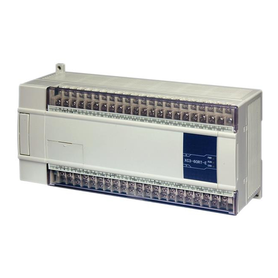
1-3.Each Part's Description CPU Unit Expansion XC3-32R-E PORT1 PORT2 COM0 COM1 COM2 COM4 COM3 Each part's name is listed below: Number Name Number Name Input & power supply terminals Installation holes (2) Input terminal label Screws to install/remove the terminals Port to install BD card Input LED COM2... -
Page 17: The Specifications And Parameters Of Cpu
2 The Specifications and Parameters of CPU The Specifications and Parameters of CPU This chapter mainly tells the general specifications, performance, external dimension, terminals arrangement and communication interface of the CPU units. For the expansions, please refer to chapter 8. 2-1.Specifications and Parameters 2-2.External Dimension 2-3.Terminals Arrangement... -
Page 18: Specifications And Parameters
※2:10I/O、14I/O、16I/O CPU units don't have COM2; ※3:COM3 is the COM port from BD card (XC-COM-BD). ※4:COM4 is only equipped on XC series. ※5:The rail is DIN46277, width is 35mm. ※6:The grounding should be like type 1 and 2, not 3. -
Page 19: Performance And Specifications
2 The Specifications and Parameters of CPU 2-1-2.Performance and Specifications XC1 series Specifications Items Program Executing Form Loop scan form Program Form Instruction、Ladder Dispose Speed 0.5 us Power Off Retentive Use Flash ROM ※ 32KB User's program space Total I/O Input ※... - Page 20 2 The Specifications and Parameters of CPU D0~D99 ※ 【D100~D149】 ※ For Special Use D8000~D8029 ※ For Special Use D8060~D8079 Data Register (D) 288 words ※ For Special Use D8120~D8179 ※ For Special Use D8240~D8249 ※ For Special Use D8306~D8313 ※...
- Page 21 2 The Specifications and Parameters of CPU XC2 Series Items Specifications Program Executing Form Loop scan form Program Form Instruction、Ladder Dispose Speed 0.5 us Power Off Retentive Use Flash ROM ※ User's program space 128K Total I/O I/O points Input X0~X7 X0~X7 X0~X15...
- Page 22 2 The Specifications and Parameters of CPU ※ For Special Use D8630~D8729 FD0~FD127 Flash ROM Register (FD) ※ words For Special Use FD8000~FD8383 High Speed Dispose High speed counter, pulse output, external interruption Ability Password Protection 6 bits ASCII Self-diagnose Function Power on self-check、monitor the timer、grammar check XC3 Series Items...
- Page 23 2 The Specifications and Parameters of CPU C600~C619: single phase high speed counter C620~C629: dual-phase high speed counter C630~C639:AB phase high speed counter 16 bits counter: set value K0~32,767 Spec. 32 bits counter: set value -2147483648~+2147483647 D0~D3999 9024 ※ 【D4000~D7999】 Data Register (D) words ※...
- Page 24 2 The Specifications and Parameters of CPU T0~T99:100ms not accumulate T100~T199:100ms accumulate T200~T299:10ms not accumulate points 640 points T300~T399:10ms accumulate T400~T499:1ms not accumulate Timer T500~T599:1ms accumulate T600~T639:1ms precise time 100ms timer: set time 0.1~3276.7sec. Spec. 10ms timer: set time 0.01~327.67sec. 1ms timer: set time 0.001~32.767sec.
- Page 25 2 The Specifications and Parameters of CPU ※ Input X0~X015 X0~X021 X0~X43 Output Y0~Y011 Y0~Y015 Y0~Y27 ※ Internal Coils (X) X0~X1037 (Total 544) ※ Internal Coils (Y) Y0~Y1037 (Total 544) M0~M2999 ※ 【M3000~M7999】 Internal Coils (M) 8768 points ※ For Special Use M8000~M8767 S0~S511 Flow (S)
- Page 26 2 The Specifications and Parameters of CPU XCC series Items Specifications Program Executing Form Loop scan form Program Form Instruction、Ladder Dispose Speed 0.5 us Power Off Retentive Use Flash ROM and Li battery ※ 256KB User's program space Total I/O I/O points Input ※...
-
Page 27: External Dimension
2 The Specifications and Parameters of CPU ※ For Special Use FD8000~FD9023 Expand the internal 36864 words ED0~ED36863 ※ registers (ED) High Speed Dispose High speed counter, pulse output, external interruption Ability Password Protection 6 bits ASCII Self-diagnose Function Power on self-check、monitor the timer、grammar check ※1: The user's program space: refer to the maximum program space when download secretly. - Page 28 2 The Specifications and Parameters of CPU (Unit: mm) Graph 2 Suitable Model 73.3 Series 24 and 32 24 and 32 24 and 32 XC3-32R-E PORT1 PORT2 24 and 32 COM0 COM1 COM2 COM4 COM3 24 and 32 Graph 3 (Unit: mm) 207.4 199.4...
-
Page 29: Terminals Arrangement
2 The Specifications and Parameters of CPU 2-3.Terminals Arrangement Graph A Graph B CAN+ CAN- COM5 COM7 COM0 COM1 COM2 COM3 COM4 COM6 COM8 Graph C COM0 COM1 COM2 COM4 COM3 Graph D Graph E COM1 COM0 ... - Page 30 2 The Specifications and Parameters of CPU Graph L Graph M COM0 COM2 COM4 COM1 COM3 Graph N Graph O COM0 COM4 COM1 COM2 COM3 Graph P The Graph to the model: Graph Suitable model XC2-60、XC3- 60、XC5- 60 36/24 XC2-48、XC3- 48、XC5- 48...
-
Page 31: Communication Ports
2 The Specifications and Parameters of CPU 2-4.Communication Ports COM1 Pins of COM1: 2:PRG 4:RxD 5:TxD 6:VCC 8:GND Mini Din 8 female COM2 ※ Pins of COM2 4:RxD 5:TxD 8:GND Mini Din 8 female Program Cable Mini Din 8 male DB9 female ※1:... -
Page 32: System Structure
3 System Structure 3 System Structure As the controller, XC series PLC can connect with many types of peripheral equipments, expansions etc. In this chapter, it introduces the peripheral devices, the connection principle of CPU with expansions, installation, calculate the I/O points, input/output ID etc. -
Page 33: System Structure
3 System Structure 3-1.System Structure In the below Graph, we show the common system structure according to XC series PLC basic configuration. Via this graph, we could know the basic connection among PLC and peripheral equipments; also classic applications of PLC's each COM port, connection and expansion. -
Page 34: Peripheral Equipments
PLC etc; After installing XCPPro on your PC, use the program cable, via COM1 or COM2 on PLC (CPU Units) to link PLC with XCPPro; Program Interface ※1: Please use the program cable offered by Xinje Electronic or the cable made by yourself; the making method is showing in Chapter 2-4... -
Page 35: Human Machine Interface (Hmi)
The HMI link PLC to the operators. The HMI can send the commands from operators to PLC, and then PLC executes the commands. XC series PLC support diverse brands of HMI; the connection is based on the communication protocol. Generally communicate via Modbus protocol, the detailed parameters setting depends on the HMI. -
Page 36: Network Module
Interface: RS232、RS485 Communication: work with many PLC brands. Communicate with Xinje Inverters RTC: Real Time Clock 3-2-3.Network Module PLC can build Modbus network, the special models can build CANBUS network. If the basic units configure with the special network module, they can connect to GPRS network, Ether net etc. - Page 37 3 System Structure Suitable for distributed system and remote control applications. T-BOX As industrial Ether Net module, T-BOX supports Modbus-RTU devices; the design is applied to industrial Ether net control system. Remote integral maintenance and diagnose of PLC program on IP devices; ...
-
Page 38: Configuration Principle
3-3.Configuration Principle About COM port XC series PLC (CPU units) are usually equipped with COM1 and COM2. Normally, both COM ports can be used to program, download, communication; but please make sure not change the parameters on two COM ports at one time, or the COM ports can't be used to program and download anymore;... - Page 39 3 System Structure How to Calculate the I/O Points Basic Unit XC3-32R-E (18I/14O) connects with five expansions: XC-E8X8Y、 XC-E16X、XC-E32Y、XC-E2AD、XC-E4DA. Then the total I/O points should be: Input Points: 18 + 8 + 16 = 42 Output points: 14 + 8 +32 = 54 Total points: Input+ Output = 42+54=96...
-
Page 40: Id Assignment Of Expansions
3 System Structure 3-4.ID Assignment of Expansions Expansion Maximum Type ID (As Register) Position points/channels Digital Input X X100~X137 32 points Digital Output Y Y100~Y137 32 points Position Analog Input ID ID100~ID131 16 channels QD100~QD131 Analog Output QD 16 channels Module's Value D D8250~D8259 Digital Input X... - Page 41 3 System Structure QD1000~QD1031 Analog Output QD 16 channels Module's Value D D8320~D8329...
-
Page 42: Install The Products
3 System Structure 3-5.Install the Products Installation Position Installation Method Use DIN or screws to install the CPU units and expansions. Use DIN46277 Directly install by screws M3 Screw DIN installation... - Page 43 3 System Structure Installation Environment Please install the products according to chapter 2-1-1...
-
Page 44: Power Supply Specification And Wiring Method
4 power supply specification and wiring method Power Supply Specification and Wiring Method In this chapter, we tell the structure, specification and external wiring of XC series PLC. The wiring method differs according to different models. The mainly difference is the wiring terminals. -
Page 45: Power Supply Specifications
4 power supply specification and wiring method 4-1.Power Supply Specifications The power supply specifications of XC series PLC are listed below: AC Power Supply Items Content Rated Voltage AC100V~240V Allow Voltage Range AC90V~265V Rated Frequency 50/60Hz Allow momentary power off time Interruption Time≤0.5 AC cycle, interval≥1sec... -
Page 46: Ac Power Dc Input Type
4 power supply specification and wiring method 4-2.AC Power DC Input Type Connection · ※1:Connect the power supply to L, N terminals ※2:24V、COM can supply 400mA/DC24V power supply. Do not give these two terminals power supply ※3: terminals are blank terminals, please do not wire them or use them as middle relays ※4:Please connect the COM terminals on basic units and expansions together... -
Page 47: Input Specifications And Wiring Methods
5 Input Specifications and Wiring Methods Input Specifications and Wiring Methods In this chapter, we tell the input specification and external wiring methods of XC series PLC. The connection method differs according to different model; the main reason is the terminal’s position. For each model’s terminal arrangement, please refer to chapter 2-3. -
Page 48: Input Specification
5 Input Specifications and Wiring Methods 5-1.Input Specification Basic Units Input signal’s voltage DC24V±10% Input signal’s current 7mA/DC24V Input ON current Up to 4.5mA Input OFF current Low than 1.5mA Input response time About 10ms Input signal’s format Contact input or NPN open collector transistor Circuit insulation Photo-electricity coupling insulation Input action’s display... -
Page 49: Dc Input Signal (Ac Power Supply Type)
5 Input Specifications and Wiring Methods 5-2.DC Input Signal (AC Power Supply Type) Input Signal... - Page 50 External circuit used by sensors XC series PLC input power is from its interior 24V power, if the exterior power drives photo-electricity sensor etc., this exterior power should be DC24V±4V. Please use NPN open collector type for sensor output transistor...
- Page 51 5 Input Specifications and Wiring Methods...
-
Page 52: High Speed Counter Input
5 Input Specifications and Wiring Methods 5-3. High Speed Counter Input XC series PLC support high speed count function which is independent with the scan cycle. Via choosing different counter, testing the high speed input signal comes from sensor and rotary encoder. - Page 53 5 Input Specifications and Wiring Methods decrease according to the direction status. If the count direction is OFF, do increment count with the input’s rising edge; if the count direction is ON, do decrement count with the input’s rising edge; AB Phase Mode Under this mode, the HSC value increase or decrease according to the two difference signal (A phase or B phase).
-
Page 54: High Speed Count Range
5 Input Specifications and Wiring Methods Four-time Frequency Mode 5-3-2. High Speed Count Range The HSC’s count range is: K-2,147,483,648 ~ K+2,147,483,647. If the count value exceeds this range, up-flow or down-flow appears; The up-flow means: the count value jumps from K+2,147,483,647 to be K-2,147,483,648 then continue to count;... -
Page 55: Input Terminals Assignment
5 Input Specifications and Wiring Methods Pulse+Direction Mode AB Phase Mode 5-3-3.Input Terminals Assignment 1、High Speed counters Assignment of XC series PLC: High speed counter channels PLC model Incremental Pulse+direction phase mode mode mode XC2 series XC3 series 24/32/42 48/60... - Page 56 5 Input Specifications and Wiring Methods XCC series 2、Input Terminals of HSC: Each letter’s description: Counter's pulse input Counter's direction judgment A phase input B phase input (OFF: increment counter, ON: decrement counter) Normally, X0, X1 terminals’ input frequency can reach 80KHz under single-phase and AB phase mode;...
- Page 57 5 Input Specifications and Wiring Methods XC3 -14 PLC Increment Mode Pulse + direction mode AB phase mode C600 C602 C604 C606 C608 C610 C612 C614 C616 C618 C620 C622 C624 C626 C628 C630 C632 C634 *Max. 10K 10K 10K 10K 10K 10K 5K 5K Frequency...
- Page 58 5 Input Specifications and Wiring Methods XC3-48、60 PLC Increment Mode Pulse + direction mode AB phase mode C600 C602 C604 C606 C608 C610 C612 C614 C616 C618 C620 C622 C624 C626 C628 C630 C632 C634 Max. 80K 80K 10K 10K 80K 80K 80K 80K Freq.
- Page 59 5 Input Specifications and Wiring Methods XC5-24/32 PLC、XCM-24/32 T4 PLC Increment Mode Pulse + direction mode AB phase mode C600 C602 C604 C606 C608 C610 C612 C614 C616 C618 C620 C622 C624 C626 C628 C630 C632 C634 Max. 80K 10K Freq.
- Page 60 5 Input Specifications and Wiring Methods XCM-24/32 T3 Increment Mode Pulse+Direction Mode AB phase Mode C600 C602 C604 C606 C608 C610 C612 C614 C616 C618 C620 C622 C624 C626 C628 C630 C632 C634 Max. Freq. 80K 10K 10K 10K 80K 10K 80K 10K 4-time √...
-
Page 61: Ab Phase Counter's Frequency Multiplication Setting
4 time frequency ※1:For more information about high speed counter, please refer to XC series PLC instruction manual ※2:To some special model, only one axis can be set as one time frequency or 4 times frequency, the left two axes... -
Page 62: Output Specification And Wiring Methods
6 Output Specification and Wiring Methods In this chapter, we tell the output specification and external wiring methods of XC series PLC. The connection method differs according to different model; the main reason is the terminal’s position. For each model’s terminal arrangement, please refer to chapter 2-3;... -
Page 63: Output Specification
6-1.Output Specification Relay Output Interior power Below AC250V、DC30V Circuit insulation Mechanism insulation Action denote LED indicate lamp Resistant load load Induce load 80VA Lamp load 100W Open circuit’s leak current Mini load DC5V 2mA Response OFF→ON 10ms time ON→OFF 10ms... - Page 64 Normal Transistor Output Interior power Below DC5~30V Circuit insulation Optical coupling insulation Action denote Indicate lamp LED Resistance load 0.5A load Induce load 12W/DC24V Lamp load 1.5W/DC24V Open circuit’s leak current Mini load DC5V 2mA Response OFF→ON Below 0.2ms time ON→OFF Below 0.2ms...
-
Page 65: Relay Output Type
High Speed Pulse Output Model RT or T Type High Speed Pulse Output Terminal Common models are Y0、Y1;XC5-24/32 model is Y0~Y3 External Power Supply Below DC5~30V Action Indication LED Lamp Maximum Current 50mA Max output frequency of pulse 200KHZ Note: 1. XCM-24/32T4、XCM-24/32T3、XCM-60T、XCC-32: the high speed pulse output terminals are Y0~Y3、Y0~Y2、Y0~Y11、Y0~Y4. - Page 66 Action display LED lamp lights when output relay’s coils galvanize, output contacts are ON. Response time From the output relay galvanize (or cut) to the output contacts be ON (or OFF), the response time is about 10ms Output current The current-voltage below AC250V can drive the load of pure resistance 2A/1 point、...
- Page 67 Constitution of output circuit For DC induce load, please parallel connect with commutate diode. If not connect with the commutate diode, the contact’s life will be decreased greatly. Please choose the commutate diode which allow inverse voltage endurance up to 5~10 times of the load’s voltage, ordinal current exceeds load current.
-
Page 68: Transistor Output Type
6-3.Transistor Output Type Transistor output models support high speed pulse output and normal transistor these two types; Normal Transistor Output Output Terminals There are 1~4 COM outputs on transistor output type CPU units External Power Supply Please use DC5~30V power supply to drive the load drive. ... - Page 69 E.g.: Below is the connection diagram of RT/T type PLC with servo driver: PLC side Servo Driver (Make sure the driver’s optical couple’s input terminal has 8~15mA reliable current)
-
Page 70: Run, Debug, Maintenance
7 run debug maintenance 7 Run, Debug, Maintenance In this chapter, we tell the whole using process of PLV, from programming till using. It includes running, debug and maintenance of PLC. 7-1.Run and Debug 7-2.Daily Maintenance... -
Page 71: Run And Debug
7 run debug maintenance 7-1.Run and Debug Check the Products When get the products, please check if the input/output terminals are correct, if there is any component missed. Generally, you can power on the PLC directly at this time. Check if PWR and RUN LED are ON. Write and Download the Program After confirming the products, please write the program for PLC. -
Page 72: Daily Maintenance
7 run debug maintenance If ERR LED keeps be ON, it indicates that PLC running is in error, please correct the program in time If PWR LED is OFF, it indicates that the power supply is in error, please check your wiring;... -
Page 73: Expansion Devices
8 expansion devices 8 Expansion Devices XC series PLC expansions include expansion modules and expansion BD cards. The expansion modules include input/output expansion module, analogue, temperature expansion modules; BD cards include analogue temperature, communication applications etc. Via the expansion devices, XC series PLC is applied widely to temperature, flow, liquid, pressure fields etc. -
Page 74: Modules Summary
8 expansion devices 8-1.MODULES SUMMARY General Specifications Item Content Using environment No corrosive gas Environmental Temperature 0℃~60℃ Stock temperature -20~70℃ Environmental Humidity 5~95% Stock Humidity 5~95% Installation Use M3 screws to fix or install on DIN46277 (width 35mm) DIN Module’s Structure Name Function Power Supply Indication... - Page 75 Graph 2 (Unit: mm) Suitable Models 73.3 Module Type Model Digital 32I/O Input/output XC3-32R-E PORT1 PORT2 Analogue None COM0 COM1 COM2 COM4 COM3 Temperature None Mixture None Module Configuration XC series modules can connect on the right side of XC-PLC main units:...
-
Page 76: Digital Input/Output Modules
8 expansion devices Digital input/output quantity is in octal form; Input/output analog is in decimal form PLC main units can work with seven expansions and one extra BD card. The expansion module can be any type (analog or digital, temperature); 8-2.Digital Input/output Modules Input/output expansions, I/O ranges 8~32, Input type, output type, input/output type, transistor output, relay output etc. - Page 77 8 expansion devices Module Specification Power Supply Specification DC24V (32 I/O expansions is AC220V) Input Specification Input Items Content Input signal’s voltage DC24V±10% Input signal’s current 7mA/DC24V Input ON current Up to 4.5mA Input OFF current Low than 1.5mA Input response time About 10ms Input signal’s format...
- Page 78 8 expansion devices Min load DC5V 2mA OFF ON Response time Below 0.2ms ON OFF Below 0.2ms Terminal Arrangement XC-E8X XC-E8YR, XC-E8YT COM3 COM0 COM1 COM2 XC-E8X8YR, XC-E8X8YT COM3 COM0 COM1 COM2 XC-E16X XC-E16YR, XC-E16YT COM3 COM0...
-
Page 79: Analogue, Temperature Modules
XC-E16X16YR 8-3.Analogue, Temperature Modules As the special modules of XC series PLC, analogue and temperature modules can work with XC series PLC, apply in process controls like temperature, pressure, flow etc. For details, please refer to《XC series analogue/temperature expansions manual》... -
Page 80: Xc-E8Ad
8 expansion devices 8-3-1.XC-E8AD Brief Introduction 14 bits high precision analog input 8 channels analog input:The first four channels voltage input (0~5V、 0~10V two kinds);The left 4 channels current input (0~20mA、4~20 mA two kinds) As special function module of XC, 7 models could be connected at most. ... -
Page 81: Xc-E4Ad2Da
0~10V selectable, current input range is 0~20mA, 4~20mA selectable; 14 bits high precision analogue input; As the special module, 7pcs XC-E4AD2DA can be connected to one XC series PLC main unit; XC-E4AD2DA module four A/D channels have PID function. -
Page 82: Xc-E4Ad
8 expansion devices 1/16383(14Bit); the convert data is 1/4095(12Bit); the convert data is stored Distinguish Ratio stored in PLC in form of Hex. (14Bit) in PLC in form of Hex. (14Bit) PID Output Value 0~K4095 Integral precision 0.8% Convert Speed 20ms/CH 3ms/CH DC24V±10%, 100mA... - Page 83 10V selectable, current input range is 0~20mA、4~20mA selectable; 14 bits high precision analogue input; As the special module, 7pcs XC-E4AD can be connected to one XC series PLC main unit; XC-E4AD module support PID auto tune function; Specification...
-
Page 84: Xc-E4Da
4CH analogue output: voltage and current input selectable; Voltage input range is 0~5V, 0~10V selectable, current input range is 0~20mA, 4~20mA selectable; 10 bits high precision analogue output; As the special module, 7pcs XC-E4DA can be connected to one XC series PLC main unit; Specification Items Voltage Output Current Output DC0~5V, 0~10V... -
Page 85: Xc-E2Da
2CH analogue output: voltage and current input selectable; Voltage input range is 0~5V、 0~10V selectable, current input range is 0~20mA、4~20mA selectable; 12 bits high precision analogue input; As the special module, 7pcs XC-E2DA can be connected to one XC series PLC main unit; Specification Items Voltage Output Current Output DC0~5V、0~10V... -
Page 86: Xc-E6Pt-P
1mA constant output, doesn’t effected by the environment; The distinguish precision is 0.1℃ As the special module, 7pcs XC-E6PT-P can be connected to one XC series PLC main unit; Specification Items Content Analogue Input Signal Pt100 resistor Temperature testing range -100℃~350℃... -
Page 87: Xc-E6Tca-P
8 expansion devices Terminal Arrangement NAME SIGNAL NAME SIGNAL CH0 A0 0CH thermo-resistor input terminal 1CH thermo-resistor input terminal 0CH COM of thermo-resistor input 1CH COM of thermo-resistor input CH2 A2 2CH thermo-resistor input terminal 3CH thermo-resistor input terminal 2CH COM of thermo-resistor input 3CH COM of thermo-resistor input CH4 A4 4CH thermo-resistor input terminal CH5 A5... - Page 88 8 expansion devices Specification Items Specifications Analogue Input Signal K、S、E、N、J、T、R type thermocouples Temperature testing range 0℃~1000℃ Digital Output range 0~4095, without sign 12 bits, decimal Control precision 0.1℃ Distinguish Ratio 0.1℃ Integral Precision 0.1℃ Convert Speed 20ms/CH DC24V±10%, 50mA Power Supply ※1: When no signal input, the channel’s data is 4095;...
- Page 89 Pt resistor input, the scale is PT100 3CH A/D and 4CH PT input are equipped with PID auto tune function; As the special module, 7pcs XC-E3AD4PT2DA can be connected to one XC series PLC main unit; Specification Analogue Current Input...
-
Page 90: Xc-E2Ad2Pt2Da
8 expansion devices Terminal Arrangement NAME SIGNAL NAME SIGNAL 0CH AI0 0CH current Input 1CH AI1 1CH current Input 0CH current Input COM 1CH current Input COM 2CH AI2 2CH current Input 2CH current Input COM 0CH A0 0CH temperature input 1CH A1 1CH temperature input 0CH input COM... - Page 91 8 expansion devices the data exchange quantity, expand the data memory space; Specification Items Analogue Input (AD) Temp. input(PT) Analogue output (DA) 0~ 20mA Current 4~ Analogue Input PT100 20mA 0~5V Voltage 0~10V Temperature Range -100~327℃ Max input range DC0~40mA 0~10V Current 0~5V...
-
Page 92: Expansion Bd Cards
8 expansion devices Current 0~20mA or 4~20mA AI0, AI1 input Output Voltage in digital form, range: 0~1023 VO0,VO1 terminals Input Analogue Output IO0, IO1 Current in digital form, range: 0~1023 input Three-line PT100 resistor’s input wiring is shown below: To normal PT100 resistors, wire according to the terminal’s color;... - Page 93 8 expansion devices 3) In “BD settings”, choose “Other BD”, then set BD from the right options; finally download the user program; ※1: If configure XC-COM-BD, then ‘BD config’ option should choose “BD Serial Port”...
-
Page 94: Xc-2Ad2Pt-Bd
8 expansion devices 8-4-1.XC-2AD2PT-BD Specifications 14 bits high precision analogue input 2CH voltage 0~10V、0~5V selectable; 2CH temperature input; Pt temperature resistor sensor input (Pt100 2-line form) Specification Items Voltage Input Temperature Input Analogue input DC0~5V, 0~10V (the input resistor is Pt resistor Pt100 (2-line) 300kΩ) signal... -
Page 95: Xc-Com-Bd
8 expansion devices 8-4-2.XC-COM-BD Specifications For RS-485 communication For RS-232 communication RS-232 and RS-485 can’t be used at the same time Pins ※1: TXD、RXD、GND are RS-232 pins ※2: A、B are RS-485 pins ※3: RS-232 and RS-485 can’t be used at the same time... -
Page 96: Change The Soft Components
9 change the soft components 9 change the Soft Components This chapter focuses on a special function of XC serials PLC, mapping relationship of terminals and soft components. With this special function, users reduce the maintenance job greatly. To the local operation, they will not bother with the damaged terminals any more. -
Page 97: Function Summary
This is troublesome for the user and affects the production greatly; XC series PLC breaks the one-to-one correspondence. The users only need to change the soft component’s value by HMI, then the corresponding terminal will activate. Take advantage of this improvement, the user need not replace the PLC or modify the original program in the condition of PLC terminals damaged. -
Page 98: Operation Method
9 change the soft components 9-2.Operation Method To the damaged input/output, we can change their mapping relation; replace the damaged input/output points with other. This need not change the user program. In PLC special register, we specify certain address section for user to change the mapping relation. User just finds the mapping relation of the damaged input/output;... -
Page 99: Operated By Hmi
HMI. Below is the sample: There are two screens based on ID60004 and ID60005 in XINJE TP series HMI, they are used to changing the mapping relation of input and output. We just need to put the “Screen Jump”... - Page 100 9 change the soft components Put the screen jump icon, jump to screen ID60004 Click into “Scr1”, enter the modify table Click it; you will see the pop-up window: In the pop-up window, click X2, disable the faulty terminal X2 Continue to click it;...
- Page 101 9 change the soft components In the pop-up window, click X4, replace the faulty terminal X2 with Click “Replace”, the status table will change, the original X2 changes to be , which means X2 has disabled. As in the above graphs, we need only 5 minutes replace I/O terminals. This method avoids us to modify the program, change PLC etc.
-
Page 102: Appendix Special Soft Device List
Appendix special soft device list Appendix Special soft device list Here we mainly introduce the functions of special soft device, data register and FlashROM, and introduce the address of expansion. Users can scan fast. Appendix 1-1.Special Auxiliary Relay List Appendix 1-2.Special Data Register List Appendix 1-3.Special Module Address List Appendix 1-4.Special Flash Register List... -
Page 103: Appendix 1-1.Special Auxiliary Relay List
Appendix special soft device list Appendix 1-1.Special Auxiliary Relay List PC Status (M8000-M8003) Function Description Normally ON coil M8000 keeps being ON M8000 when running status when PLC is running Normally OFF coil M8001 keeps being OFF M8001 when running status when PLC is running Initial positive pulse M8002 be ON in first scan... - Page 104 Appendix special soft device list Flag (M8020-M8029) Function Description M8020 Zero The plus/minus operation result is 0 “borrow” occurs in minus operation M8021 Borrow When carry occurs in plus operation or overflow M8022 Carry occurs in bit shift operation M8023 M8026 RAMP Mode M8029...
- Page 105 Appendix special soft device list Interruption (M8050-M8059) (M) Function Description M8050 I000□ Forbid the input interruption 0 M8051 After executing EI instruction, even the I010□ Forbid the input interruption 1 interruption is allowed, but if M acts at this M8052 time, the correspond input interruption I020□...
- Page 106 Appendix special soft device list Communication (M8120-M8148) Function Description M8120 M8121 Waiting to send via RS232 “sending by RS232” flag M8122 “RS232 receiving finish” flag M8123 M8124 RS232 receiving flag COM1 acceptance ends normally, but the accepted “Receive incomplete” flag M8125 data number is less than the required number...
- Page 107 Appendix special soft device list “High Speed Counter Interruption Finished” Flag (M8150-M 8169) Counter Function Description “Count Interruption Finished” Flag M8150 C600 Set flag ON when count interruption finish “Count Interruption Finished” Flag M8151 C602 Set flag ON when count interruption finish “Count Interruption Finished”...
- Page 108 Appendix special soft device list sending” 1 is positive direction, the correspond M8178 Direction flag direction port is on “sending pulse” flag M8179 PULSE_4 Being ON when sending the pulse, overflow flag of “32 bits pulse M8180 When overflow, Flag is on sending”...
- Page 109 Appendix special soft device list M8217 Neglect the alarm or not When flag is 1, stop sending alarm PULSE_4 Pulse alarm flag (frequency change M8218 suddenly) 1 is alarm, 0 is correct PULSE_5 M8219 Neglect the alarm or not When flag is 1, stop sending alarm PULSE_5 Positive/negative count Function...
-
Page 110: Appendix 1-2.List Of Special Memory And Special Data Register
Appendix special soft device list Read &Write the Expansions (M8340~M8341) Function Specification M8340 Read the expansion error flag (read instruction) M8341 Write the expansion error flag (write instruction) BLOCK Execution (M8630~M8730) Function Specification M8630 M8631 BLOCK1 is running flag M8632 BLOCK2 is running flag ……... - Page 111 Appendix special soft device list D8019 week (clock) 0 (Sunday)~6 (Saturday) (BCD code) Flag (D8021-D8029) Function Specification Model Low byte D8021 Series number High byte Compatible system’s version number Low byte D8022 System’s version number High byte Compatible model’s version number Low byte D8023 Model’s version number...
- Page 112 Appendix special soft device list D8123 Data number RS232 received D8126 7: hardware error 8: CRC Parity error 9: station number error D8127 Communication error code 10: no start code 11: no end code 12: communication time out 0: correct 1: don’t support function ID Modbus communication error D8128...
- Page 113 Appendix special soft device list 0:correct 1: don’t support function ID Modbus communication error D8148 (the replied message from slaves 2: address error(overrun address) when the master send errors) 3: Data error ( the number of data) 8:saving data error ( rewrite Flash) D8149 HSC Interruption Station (D8150-D8169) Counter ID...
- Page 114 Appendix special soft device list D8172 The current segment (means Nr.n segment) The low 16 bits of accumulated pulse number D8173 PULSE_2 D8174 The high 16 bits of accumulated pulse number D8175 The current segment (means Nr.n segment) The low 16 bits of accumulated pulse number D8176 PULSE_3 D8177...
- Page 115 Appendix special soft device list Testing the decimal dot, 1 means Precision *10, 2 means *100 Absolute Positioning/Relative Positioning/the Origin Return (D8230-D8239) Pulse Function Description D8230 Rising time of the absolute/relation position instruction (Y0) PULSE_1 D8231 Falling time of the origin return instruction (Y0) D8232 Rising time of the absolute/relation position instruction (Y1) PULSE_2...
- Page 116 Appendix special soft device list BLOCK100 Error information of the Expansions (D8600-D8627) Function specification Expansion ID Read the expansion’s error D8600 times Read the expansion’s error 1. expansion’s CRC parity error D8601 2. expansion’s address error 3. expansion’s accepted data length error 4.
-
Page 117: Appendix 1-3.Id List Of The Expansions
Appendix special soft device list Appendix 1-3.ID List of the Expansions Take the first expansion module as the example: PID parameter: Kp, Ki, Channel Output run/stop Set value Kd, control range Diff、 signal signal value Death range death XC-E8AD ID100 ID108 Y100 QD100... - Page 118 Appendix special soft device list XC-E6PT-P/ XC-E6TC-P Current The first 3CH The last 3CH CH Nr. Set temp. PID run/stop bit temp. PID value PID value ID100 QD100 Y100 ID101 QD101 Y101 Kp:QD106 Kp:QD110 ID102 QD102 Y102 Ki:QD107 Ki:QD111 Kd:QD108 Kd:QD112 ID103 QD103...
- Page 119 Appendix special soft device list value; if the temperature is higher than , PID output the mini value; (sample temperature+ Temperature difference δ)/10=display temperature value. Then Temperature difference δ temperature display value can equal or close to the real temperature value. This (unit: 0.1℃) parameter has sign (negative or positive).
- Page 120 Appendix special soft device list CH Nr. signal QD100 QD101 XC-E2AD2PT2DA RELATIVE COMMENTS AND DESCRIPTIONS PARAMETERS PT0(0.01℃) PT1(0.01℃) ID100 ID101 ID102 ID103 Display temperature module 1 (unit: 0.1℃) PID output X100 X101 X102 X103 (X input which returns module 1 to main unit) Connecting status X110...
-
Page 121: Appendix 1-4.Special Flash Register List
Appendix special soft device list (unit: 0.1℃) has sign (negative or positive). Unit is 0.1℃, the default value is 0. The set temperature Control system’s target temperature value. The range is 0~1000℃, the precision is 0.1℃. value(unit: 0.1℃) Control cycle’s range is 0.5s~200s, the minimum precision is 0.1s. The write value is the Temperature control cycle (unit: 0.1s) real temperature control cycle multiplies 10. - Page 122 Appendix special soft device list 3、 O mapping Function Initial value Description FD8074 Y00 corresponds with I** Y0 corresponds with the number of output image O** FD8075 Y01 corresponds with I** Initial value are all decimal FD8076 Y02 corresponds with I** ……...
- Page 123 Appendix special soft device list Start tag of D power off FD8202 4000 D4000~D7999 retentive area Start tag of M power off FD8203 3000 M3000~M7999 retentive area Start tag of T power off FD8204 retentive area series Start tag of C power off FD8205 C320~C639 retentive area...
- Page 124 Appendix special soft device list 6、 Communication Function Initial Description Communicate Mode 255 (FF) is free mode, FD8210 (station number) 1~254 is modbus station number Baud rate, Data bit, stop bit, FD8211 Communicate format 8710 parity Judgment time Unit ms, if set to be 0, it means no FD8212 timeout timeout waiting...
- Page 125 Appendix special soft device list ※1:If you change special FLASH memory, it will take into effect after restart the PLC...
-
Page 126: Appendix 2 Instructions List
Appendix 2 instructions list Appendix 2 Instructions List In this chapter, we will list all the instructions XC series PLC support. These instructions include: basic instructions, application instructions, special function instructions and motion control instructions. Also, we declare each instruction’s application range. -
Page 127: Appendix 2-1.Basic Instructions List
Appendix 2 instructions list Appendix 2-1.Basic Instructions List Mnemonic Function Initial logical operation contact type NO (normally open) Initial logical operation contact type NC (normally closed) Final logic operation type coil drive Serial connection of NO Serial connection of NC Parallel connection of NO Parallel connection of NC Rising edge pulse... -
Page 128: Appendix 2-2.Applied Instruction List
Appendix 2 instructions list Appendix 2-2.Applied instruction list Suit Model Sort Mnemonic Function XC1 XC2 XC3 XC5 XCM √ √ √ √ √ Condition Jump √ √ √ √ √ CALL Call subroutine √ √ √ √ √ SRET Subroutine return √... - Page 129 Appendix 2 instructions list Suit model Sort Mnemonic function XC1 XC2 XC3 XC5 XCM ※ √ √ √ √ √ addition ※ √ √ √ √ √ subtraction √ √ √ √ √ ※ multiplication √ √ √ √ √ ※...
-
Page 130: Appendix 2-3.Special Instructions List
Appendix 2 instructions list Suit Model Sort Mnemonic function XC1 XC2 XC3 XC5 XCM ※ √ √ √ √ Float compare ECMP ※ √ √ √ √ Float zone compare EZCP √ √ √ √ ※ Float addition EADD √ √... -
Page 131: Appendix 2-4.Motion Control Instructions List
Appendix 2 instructions list √ √ √ √ COLR MODBUS coil read √ √ √ √ INPR MODBUS input coil read √ √ √ √ COLW MODBUS single coil write √ √ √ √ MCLW MODBUS multi coil write MODBUS √... - Page 132 Appendix 2 instructions list √ Servo end check ※ √ Circular clockwise interpolation √ ※ High speed √ DRVR Electrical zero return √ DRVZ Machine zero return √ ※ Follow movement FOLLOW instruction √ Incremental address √ ※ Linear interpolation positioning √...
-
Page 133: Appendix 3 Version For Special Function
Appendix 3 version for special function Appendix 3 Version for special function Generally, the functions and instructions described in this manual don’t have software and hardware requirements. But for some special functions, we have software and hardware versions requirement. Below, we list these requirements for the special functions; function Hardware Software... -
Page 134: Appendix 4 Plc Configuration List
Appendix 3 version for special function Appendix 4 PLC Configuration List This part is used to check each model’s configurations. Via this table, we can judge the model easily; ○ selectable ×Not support √support communication NO. of high speed counter No. - Page 135 Appendix 3 version for special function ○ × √ √ √ √ ※ XCM-24/ 32T3 ○ × √ √ × √ XCM-60 ※ XCC Series ○ √ √ √ √ √ XCC-32 ※1:If use BD board, Y1 can’t be used for pulse ※2:it just can be used for Modbus slave.
-
Page 136: Appendix 5 Common Question A&Q
Appendix 5 common question A&Q Appendix 5 common question A&Q The following are the common questions may happen when using the PLC. Q1:why the coil is not set when the condition is satisfied? A1:the probable reasons: (1)use one coil for many times, double coils output, the later coil has priority. (2)some conditions reset the coil, please use monitor function to find the reset point and modify the program. - Page 137 Appendix 5 common question A&Q (1) Check if the thermocouple cold point is short with the outside cover. If short, please change another thermocouple. (2) the weak electricity such as outside interference, thermocouple, temperature module should separate from the strong electricity, make sure there is certain distance between them. If the device has motor, inverter, make sure to connect the ground correctly.
- Page 138 WUXI XINJE ELECTRIC CO., LTD. 4th Floor, Building 7th, No.100 Dicui Rd, Wuxi, China Tel: 86-0510-85134139 Fax: 86-0510-85111290 Web: www.xinje.com Email: cheerfiona@gmail.com...
Need help?
Do you have a question about the XC Series and is the answer not in the manual?
Questions and answers
ترجمة بالفرنسية
xc-E6tca-p manuel en français