Table of Contents
Advertisement
Advertisement
Table of Contents

Summary of Contents for ENERCON E-82 E4
- Page 1 Technical Description ENERCON Wind energy converter E-82 E4...
- Page 2 The entire content of this document is protected by the German Copyright Act (UrhG) and international agreements. All copyrights concerning the content of this document are held by ENERCON GmbH, unless another copyright holder is expressly indicated or identified. Any content made available does not grant the user any industrial property rights, rights of use or any other rights.
-
Page 3: Table Of Contents
Table of contents Table of contents Overview of ENERCON E-82 E4 ................ENERCON wind energy converter concept ............E-82 E4 components .................... Rotor blades ......................Nacelle ........................3.2.1 Annular generator ................. Tower ........................Grid Management System ..................Safety system ....................... - Page 4 Table of contents D0376616-2 / DA...
-
Page 5: Overview Of Enercon E-82 E4
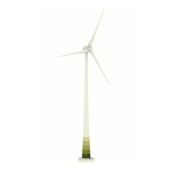
Overview of ENERCON E-82 E4 Overview of ENERCON E-82 E4 The ENERCON E-82 E4 wind energy converter is a direct-drive wind energy converter with a three-bladed rotor, active pitch control, variable speed operation, and a nominal power output of 2350/3000 kW. It has a rotor diameter of 82 m and can be supplied with hub heights of 59 m to 84 m. -
Page 6: Enercon Wind Energy Converter Concept
ENERCON wind energy converters are characterised by the following features: Gearless The E-82 E4 drive system comprises very few rotating components. The rotor hub and the rotor of the annular generator are directly interconnected to form one solid unit. This reduces the mechani‐... -
Page 7: 82 E4 Components
E-82 E4 components E-82 E4 components Fig. 2: View of nacelle 1 Slip ring unit 8 Generator filter cabinet 2 Hub 9 Excitation controller box 3 Blade adapter 10 Nacelle converter cabinet 4 Generator stator 11 Yaw drives 5 Generator rotor... -
Page 8: Rotor Blades
In combination with the streamlined nacelle, utilisation of the wind supply is considerably optimised. The rotor blades of the E-82 E4 were specially designed to operate with variable pitch control and at variable speeds. The PU-based surface coating protects the rotor blades from environmental im‐... -
Page 9: Tower
E-82 E4 components Tower The tower of the E-82 E4 wind energy converter is either a steel tower or a concrete tower made of precast segments. Towers with different heights are available. All towers are painted and equipped with weather and corrosion protection at the factory. This means that no work is required in this regard after assembly except for repairing any defects or transport damage. -
Page 10: Grid Management System
Conversely, possible grid faults have virtually no effect on WEC mechanics. The power injected by the E-82 E4 can be precisely regulated from 0 kW to 2350/3000 kW. In general, the features required for a certain wind energy converter or wind farm to be connected to the receiving power grid are predefined by the operator of that grid. - Page 11 WEC configuration. FT configuration By default, the E-82 E4 comes equipped with FACTS technology that meets the stringent require‐ ments of specific grid codes. It is able to ride through grid faults (undervoltage, overvoltage, auto‐ matic reclosing, etc.) of up to 5 seconds (FT = FACTS + FRT [Fault Ride Through]) and to remain connected to the grid during these faults.
- Page 12 ENERCON wind energy converters can be used in grids with a nominal frequency of 50 Hz or 60 Hz. The range of operation of the E-82 E4 is defined by a lower and upper frequency limit value. Over‐ frequency and underfrequency events at the WEC reference point trigger frequency protection and cause the WEC to shut down after the maximum delay time of 60 seconds has elapsed.
-
Page 13: Safety System
Safety system Safety system The E-82 E4 comes with a large number of safety features whose purpose is to permanently keep the WEC inside a safe operating range. In addition to components that ensure safe stopping of the wind energy converter, these include a complex sensor system. It continuously captures all rele‐... - Page 14 WEC operation or, where this is not possible, in the course of WEC maintenance work. Speed monitoring The control system of the ENERCON wind energy converter regulates the rotor speed by adjusting the blade angle in such a way that the speed does not significantly exceed rated speed even dur‐...
- Page 15 Temperature monitoring The components of the ENERCON wind energy converter are cooled by an air cooling system. In addition, temperature sensors continuously measure the temperature of WEC components that need to be protected from excessive heat.
-
Page 16: Control System
WEC components and collect data such as wind direction and wind speed. Using this information, it adjusts the operating mode of the E-82 E4 accordingly. The WEC display of the control cabinet in the tower base shows the current status of the wind energy con‐... -
Page 17: Wec Start
Control system Blade angles Special rotor blade positions (blade angles) of the E-82 E4 : A: 2.5° Regular position during partial load operation: Maximum exploitation of available wind energy. B: 60° Idle mode (wind energy converter does not feed any power into the grid because the wind speed is too low): Depending on the wind speed, the rotor spins at low speed or stands still (if there is no wind at all). -
Page 18: Wind Measurement And Nacelle Alignment
The power increase gradient (dP/dt) after a grid fault or a regular start-up can be defined within a Grid Performance data certain range in the control system. For more detailed information, see the sheet for the particular ENERCON WEC type. D0376616-2 / DA 14 of 21... -
Page 19: Operating Modes
Control system Operating modes After completion of the E-82 E4 start-up procedure the wind energy converter switches to automat‐ ic mode (normal operation). While in operation, the WEC constantly monitors wind conditions, opti‐ mises rotor speed, generator excitation and generator power output, aligns the nacelle position with the wind direction, and captures all sensor statuses. -
Page 20: Partial Load Operation
Control system 6.4.2 Partial load operation Wind speed 2.5 m/s ≤ v < 13.9 (2.35 MW) / 16 (3 MW) m/s During partial load operation (i.e., the wind speed is between the cut-in wind speed and the rated wind speed) the maximum possible power is extracted from the wind. Rotor speed and power out‐ put are determined by the current wind speed. -
Page 21: Safe Stopping Of The Wind Energy Converter
Control system Safe stopping of the wind energy converter The ENERCON wind energy converter can be stopped by manual intervention or automatically by the control system. The causes are divided into groups by risk. Wind energy converter stop during Fault Normal operation e.g. -
Page 22: Remote Monitoring
Connection of the individual wind energy converters is through a dedicated personal computer (ENERCON SCADA Server), which is typically located in one of the wind farm wind energy con‐ verters or in the associated substation. There is one ENERCON SCADA Server in every wind farm. -
Page 23: Maintenance
Maintenance Maintenance In order to ensure the long-term safe and optimum operation of the wind energy converter, mainte‐ nance is required at regular intervals. Frequency One mechanical maintenance, one visual maintenance, one grease maintenance and one electri‐ cal maintenance are carried out per year. The maintenance activities are spread out over the year so that every wind energy converter is being serviced once per quarter. -
Page 24: Technical Specifications E-82 E4
Lowest power feed speed to 5.5 - 17.5 rpm nominal speed Tip speed Up to 77.28 m/s Power reduction wind speed 28 - 34 m/s (with optional ENERCON storm control) Conical angle 0° Rotor axis angle 5° Pitch control One independent electrical pitch system per rotor blade with... - Page 25 Gearless; variable speed; full-scale converter Rigid Storage Double-row tapered/cylindrical roller bearing Generator Direct-drive ENERCON annular generator Grid feed ENERCON inverters with high-frequency IGBT switching and sinusoidal current IP Code/insulation class IP 23/F Brake system Aerodynamic brake Three independent pitch systems with emergency power sup‐...
Need help?
Do you have a question about the E-82 E4 and is the answer not in the manual?
Questions and answers