Table of Contents
Advertisement
Advertisement
Table of Contents

Related Manuals for Sensors & Software Noggin 100


Summary of Contents for Sensors & Software Noggin 100
- Page 1 Noggin User’s Guide © Copyright 2012 Sensors & Software Inc. 2011-00022-02...
- Page 5 SENSORS & SOFTWARE INC. PRODUCT LICENSE, COPYRIGHT, LIABILITY AND WARRANTY INFORMATION Important Please read this document carefully before using the or assembling the . By SOFTWARE PRODUCT HARDWARE PRODUCT using the storage media or assembling the hardware, you are agreeing to be bound by the terms of this agreement. If you do not agree to the terms of this agreement, promptly contact Sensors &...
- Page 6 SSI makes no other warranties including, but not limited to, any implied warranty of merchantability or fitness for a particular purpose. If this product is defective within the warranty period stated above, your exclusive remedy shall be, at SSI’s option to replace or repair the SSI product or refund the purchase price of the SSI product. Except where prohibited by law, SSI will not be liable for any loss or damage arising from this SSI product, whether direct, indirect, special, incidental or consequential regardless of the legal theory asserted.
- Page 7 Governing Law In the event of any conflict between any provision in this license agreement and limited warranty and any applica- ble provincial legislation, the applicable provincial legislation takes precedence over the contravening provision. This agreement shall be governed and construed in accordance with the laws of the Province of Ontario, Canada. Serviceability Should any term of this agreement be declared void or not enforceable by any court of competent jurisdiction, the remaining terms shall remain in full effect.
-
Page 9: Table Of Contents
Noggin 100 ........ - Page 10 Table of Contents Noggin 7 SmartHandle Configuration Assembly (Noggin 500 & 1000 only) SmartHandle “Pull” Configuration .......35 Cable Connections .
- Page 11 Noggin Table of Contents 12.3.2.3 Soil Moisture.........61 12.3.3 Identifying Air Wave Reflections.
- Page 12 Table of Contents Noggin 13.2.4.1 Depth Lines .........80 13.2.4.2 Fiducial Markers .
- Page 13 Noggin Table of Contents 13.3.4.3 Line Spacing ........110 13.3.4.4 Survey Format .
- Page 14 Noggin Table of Contents 15.2 DVL Internal Battery .........126 15.3 Cable Care .
-
Page 15: General Overview
Noggin 1-General Overview General Overview Noggins are completely self-contained Ground Penetrating Radar (GPR) systems. Once the unit has been assembled into its deployment configuration and powered up you can be carrying out a GPR survey in less than a minute. There are several different Noggin configurations available: Base, SmartCart, SmartHandle, SmartTow and the Rock Noggin. -
Page 16: Noggin Components
Noggin Noggin Components The Noggin family of GPR systems consists of the Noggin 100, 250, 500 and 1000. The name reflects the center frequency of the GPR signals in MHz. The basic configuration and key components of the Noggin 250, 500 and 1000 are shown in Figure 2-1 and Figure 2-2. - Page 17 Noggin 2-Noggin Components Figure: 2-3 Noggin 100 components...
-
Page 18: Noggin 100 Assembly
Noggin Noggin 100 Assembly Unlike the higher frequency Noggins (250, 500 and 1000 MHz), the Noggin 100 comes with the antennas and electronics as separate units that need to be assembled. To assemble, space the 100 MHz antennas about 0.5 meters apart with the mounting blocks facing up. - Page 19 Secure using the electronics to the antenna using the 2 plastic latches. Figure: 3-3 Latching the electronics to the antenna. Do the same to connect the electronics to the second antenna. See the complete assembly of the Noggin 100 in Figure 2-3.
-
Page 20: Base Configuration Assembly
4-Base Configuration Assembly Noggin Base Configuration Assembly The Base Noggin Configuration consists of the parts shown in Figure 4-1 (a Noggin 500 is shown but any Noggin (100, 250, 500 or 1000) could be included). The assembled system is shown in Figure 4-2. Follow the directions below to assemble the configuration. Noggin Battery Connection... - Page 21 Noggin 4-Base Configuration Assembly The DVL-to-Noggin cable is a Y-shaped cable with 3 connections; one to the Noggin sensor, one to the DVL and one to the battery or the AC power supply. Noggin Connection: Connect the 37-pin D-connector on the black cable to the 37-socket D- connector on the Noggin.
- Page 22 4-Base Configuration Assembly Noggin Power Connection: The third connection on the SmartHandle cable attaches to a power supply. The round, 4-pin connector attaches to the belt battery. The base configuration has all the components necessary for data acquisition in Free Run or Button modes (13.3.2.2: p.98).
-
Page 23: Smartcart Configuration Assembly
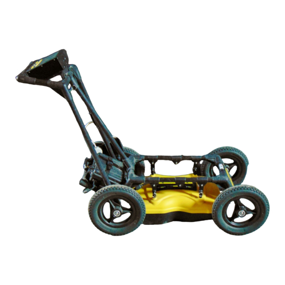
The fully-assembled Noggin 250 in the SmartCart configuration is shown in Figure 5-1. The system is shown in field operation in Figure 5-2. Follow the directions below to assemble the configuration. Figure: 5-1 Fully assembled SmartCart with a Noggin 250. Figure: 5-2 Noggin 250 SmartCart (left) and Noggin 100 SmartCart (right) in operation. -
Page 24: Unfold The Handle
5-SmartCart Configuration Assembly Noggin 5.1 Unfold the Handle The Noggin SmartCart comes folded for transportation and storage (Figure 5-3). Figure: 5-3 SmartCart in collapsed position. To unfold the SmartCart, refer to Figure 5-4. Pull the ring to remove the handle Clevis pin from the handle support arm. -
Page 25: Attach Wheels
Noggin 5-SmartCart Configuration Assembly 5.2 Attach Wheels The SmartCart may have been shipped without the wheels attached or they may have been removed for storage. If this is the case, find the axle for each wheel, press the button on the end of the axle, and insert the axle through the wheel and into the SmartCart frame (Figure 5-5). -
Page 26: Attaching Separation Bars To The Smartcart
5.3 Attaching Separation Bars to the SmartCart The Noggin SmartCart can be configured to carry a Noggin 100, 250, 500 or 1000 system. Each system has a unique set of separation bars used to attach the Noggin to the SmartCart and suspend it over the surface (Figure 5-7). -
Page 27: Attaching The Swivel Adapters (Noggin 250, 500 & 1000)
Noggin 5-SmartCart Configuration Assembly 5.4 Attaching the Swivel Adapters (Noggin 250, 500 & 1000) Before the Noggin 250, 500 or 1000 can be attached to the SmartCart, the 4 swivel adapters (with attached Clevis pins) must be attached to the mounting posts on the Noggin (see Figure 2- 1). -
Page 28: Attaching The Noggin To The Smartcart
5-SmartCart Configuration Assembly Noggin 5.5 Attaching the Noggin to the SmartCart The Noggin is attached to the cart with the long axis of the Noggin unit parallel to the wheels on the cart (see Figure 5-9 and Figure 5-10). Ensure the 37 socket female electrical receptacle on the Noggin faces the back of the cart so that the cable on the cart will reach the receptacle. -
Page 29: Noggin 500 & Noggin 1000
Noggin 5-SmartCart Configuration Assembly 5.5.2 Noggin 500 & Noggin 1000 Remove the Clevis pins from the swivel adapters. Now, on the bottom of the cart, locate the two, flat, moveable crossbars suspended from the separation bars. Notice that each crossbar has 2 holes, one on each side. To attach the Noggin 500 to the cart, place the crossbars into the slots on the top of the swivel adapters, line up the holes and insert the Clevis pins (Figure 5-10). -
Page 30: Noggin 100
The 37 socket receptacle on the Noggin 100 electronics must face the back of the SmartCart for the cable to connect properly. Figure: 5-12 Secure the SmartCart Separation Bars to the Noggin 100 by inserting the pins into each of the 8 post blocks. -
Page 31: Noggin Cable Connection
The cable should have a little slack to reduce any stresses on the cable during data collection. For the Noggin 100, ensure that the cable does not sag and contact the electronics or antennas as this will cause noise in the data. -
Page 32: Attach The Digital Video Logger (Dvl)
5-SmartCart Configuration Assembly Noggin 5.7 Attach the Digital Video Logger (DVL) The bottom of the Digital Video Logger is designed to slide onto the support shelf attached to the SmartCart (Figure 5-14). Line up the bottom of the DVL with the shelf and slide it back onto the shelf. -
Page 33: Attach The Battery Unit
Noggin 5-SmartCart Configuration Assembly 5.9 Attach the Battery Unit The batteries usually used with the SmartCart are shown below. Set the battery unit onto the lower inclined shelf on the back of the SmartCart (Figure 5-15). The handle on the battery unit should be accessible from the back of the cart with the cable receptacle on the right. -
Page 34: Adding Gps Mount To The Smartcart
5-SmartCart Configuration Assembly Noggin 5.10 Adding GPS Mount to the SmartCart The SmartCart has an optional bracket designed to hold a Trimble or Novatel GPS (Figure 5-16). This bracket can be modified by the user to hold other types of GPS units. Any GPS unit with a serial output can be attached to the serial port on the back of the DVL and GPS information logged during data collection (9: p.44). -
Page 35: Smarttow Configuration Assembly
Figure: 6-1 Noggin 100 SmartTow configuration. Figure: 6-2 Noggin 100 SmartTow configuration in use. Note the belt battery for power and DVL carrier for conve- niently carrying the DVL in the field. The cable runs from the electronics housing and up the handle secured by velcro... - Page 36 Big Wheel Odometer Figure: 6-3 The Noggin 100 SmartTow frame parts (left) and assembled (right). Ensure the antenna post blocks face outward before assembling. The pieces are connected using the 4 thumb screws as shown in the figure below. The Handle and Big Wheel odometer are not connected to the frame with thumb screws but held in place once the 100 MHz antennas are attached.
- Page 37 Figure: 6-5 Place the SmartTow frame over the Noggin 100 system with the 8 antenna mounting posts inserted in the post blocks. Ensure the 37-socket connection on the Noggin 100 faces the odometer wheel. Figure: 6-6 Secure the SmartTow frame to the Noggin 100 by inserting the metal pins into each of the 8 post blocks.
- Page 38 6-SmartTow Configuration Assembly Noggin Latch the 37 pin end of the Noggin-to-DVL cable to the receptacle on the Noggin 100 electronics. Then route the cable along the frame and up the handle, keeping it away from the electronics and the antennas. Use the velcro straps to secure the cable to the frame and handle (Figure 6- 7).
-
Page 39: Noggin 250
Noggin 6-SmartTow Configuration Assembly 6.2 Noggin 250 The fully-assembled Noggin 250 in the SmartTow configuration is shown in Figure 6-1. The system is shown in field operation in Figure 6-2. Follow the directions below to assemble the configuration. Figure: 6-8 Noggin 250 SmartTow system Figure: 6-9 Noggin 250 SmartTow in operation. - Page 40 6-SmartTow Configuration Assembly Noggin Attach one of the SmartTow Bracket Assemblies to the two front mounting posts on the Noggin 250 and secure with the metal pins. Attach the second SmartTow Bracket Assembly to the two back mounting posts on the Noggin 250 and secure with the metal pins.
- Page 41 Noggin 6-SmartTow Configuration Assembly The yellow cable from the odometer connects to the receptacle on the connector to the Noggin. Odometer calibration is critical for accurate data images. Odometer calibration instructions are available in 13.5.2: p.120. Attach the handle to the front SmartTow Bracket Assembly with the U-brackets and pins. The black cable should lie between the SmartTow Bracket and the handle.
-
Page 42: Noggin 500 And 1000
6-SmartTow Configuration Assembly Noggin 6.3 Noggin 500 and 1000 The fully-assembled Noggin 1000 in the SmartTow configuration is shown in Figure 6-10. Follow the directions below to assemble the configuration. The Noggin 500 SmartTow system is assembled similarly. Figure: 6-10 Noggin 1000 in the SmartTow configuration... - Page 43 Noggin 6-SmartTow Configuration Assembly The parts for the Noggin 500/100 SmartTow Brackets are shown below. SmartTow Brackets Short Pins Long Pins U Brackets Align the two holes on one of the SmartTow Brackets with the two mounting posts on one side of the Noggin, press down firmly and secure with the short metal pins.
- Page 44 6-SmartTow Configuration Assembly Noggin Attach the handle to the front of the SmartTow Brackets with the U-brackets and long metal pins. The handle should be attached on the end of the Noggin away from the 37 socket cable connection. Handle U Brackets Long Pins Connect the large black Noggin-to-DVL cable to the 37-socket connector on the Noggin and latch...
- Page 45 Noggin 6-SmartTow Configuration Assembly The large odometer wheel attaches on the end of the Noggin with the 37-socket connector. Use the U-brackets and long metal pins to secure the odometer T-bar to the SmartTow Brackets. Orient the odometer so the black thumbscrew on the T-bar is facing upwards and the yellow odometer cable is on the same side of the odometer wheel as the odometer receptacle on the Noggin cable connection.
-
Page 46: Smarthandle Configuration Assembly (Noggin 500 & 1000 Only)
7-SmartHandle Configuration Assembly (Noggin 500 & 1000 only) Noggin SmartHandle Configuration Assembly (Noggin 500 & 1000 only) The Noggin 500 and 1000 can be operated in the SmartHandle configuration. The fully assembled Noggin 500 SmartHandle system is shown in Figure 7-1. The Noggin 1000 SmartHandle system looks very similar. - Page 47 Noggin 7-SmartHandle Configuration Assembly (Noggin 500 & 1000 only) Figure: 7-2 Slide the Noggin odometer bracket over the four, silver mounting posts for both the Noggin 1000 (top) and Noggin 500 (bottom). Figure: 7-3 Connect the 37 pin connector on the Noggin-to-DVL cable to the 37 socket receptacle on the Noggin unit by tightening the latch.
- Page 48 7-SmartHandle Configuration Assembly (Noggin 500 & 1000 only) Noggin Figure: 7-5 Press the handle base straight down onto the four, silver mounting posts. The handle base should be pushed all the way down onto the odometer bracket. Insert the four quick-release pins to secure the handle.
-
Page 49: Smarthandle "Pull" Configuration
Noggin 7-SmartHandle Configuration Assembly (Noggin 500 & 1000 only) 7.1 SmartHandle “Pull” Configuration In some situations, conditions may dictate that pushing the SmartHandle system (Figure 7-1) is not practical. An alternative configuration is to pull the SmartHandle system (Figure 7-7). To do this, remove the 4 quick-release pins that hold the handle to the Noggin system, remove the handle by pulling straight up and rotate the handle so that it faces the other direction. -
Page 50: Rock Noggin Configuration Assembly (Noggin 500 & 1000 Only)
8-Rock Noggin Configuration Assembly (Noggin 500 & 1000 only) Noggin Rock Noggin Configuration Assembly (Noggin 500 & 1000 only) Assembly of the Rock Noggin system for both the Noggin 500 and the Noggin 1000 is described in this section. The Rock Noggin 500 system is shown in Figure 8-1. The Rock Noggin 1000 system looks very similar when assembled. - Page 51 Noggin 8-Rock Noggin Configuration Assembly (Noggin 500 & 1000 only) The Rock Noggin shipping case contains the complete Rock Noggin system (Figure 8-2). Rock Noggin systems are shipped from the factory partially assembled with the frame and DVL- to-Noggin cable already attached to the Noggin unit (Figure 8-3). If your system is already partially assembled, skip to Figure 8-11.
- Page 52 8-Rock Noggin Configuration Assembly (Noggin 500 & 1000 only) Noggin Figure: 8-4 The Rock Noggin system disassembled into its basic components and ready for assembly. More details of each component are given in the figures below. Figure: 8-5 The Rock Noggin cable. The 4 connections are for the Noggin, the Digital Video Logger (DVL), the trigger button and the battery.
- Page 53 Noggin 8-Rock Noggin Configuration Assembly (Noggin 500 & 1000 only) Connector Figure: 8-6 The Noggin used with the Rock Noggin can be either a Noggin 500 (shown here) or a Noggin 1000. The connections are identical for both systems. The 4 silver mounting posts visible here are used when attaching the frame to the Noggin (see Figure 8-8).
- Page 54 8-Rock Noggin Configuration Assembly (Noggin 500 & 1000 only) Noggin Figure: 8-8 Using the 4 holes on the bottom of the Rock Noggin frame, place the frame on the 4 mounting posts on the top of the Noggin (shown in Figure 8-6). Push the frame down until it cannot go any further. The Noggin should be oriented such that the 37 socket receptacle on the Noggin is on the same side as the SmartButton on the frame.
- Page 55 Noggin 8-Rock Noggin Configuration Assembly (Noggin 500 & 1000 only) Figure: 8-10 Attach the end of the cable with the 37 pin (male) connection to the Noggin. Use a slotted screwdriver to tighten the connection. Figure: 8-11 Attach the Digital Video Logger to the frame. Attaching the digital video logger (DVL). Step 1: Depress flexible clip.
- Page 56 8-Rock Noggin Configuration Assembly (Noggin 500 & 1000 only) Noggin Figure: 8-12 Connect the end of the grey cable to the receptacle on the handle at the back of the frame. This recep- tacle is adjacent to the Smart button. Figure: 8-13 Attach the end of the cable with the 37 socket (female) connection to the back of the Digital Video Log- ger (DVL).
- Page 57 Noggin 8-Rock Noggin Configuration Assembly (Noggin 500 & 1000 only) Figure: 8-14 The last connection on the cable is a cylindrical, 4 pin connector for the battery. Figure: 8-15 The Rock Noggin system is now completely assembled and ready to be turned on.
-
Page 58: Connecting Gps
9-Connecting GPS Noggin Connecting GPS For all Noggin configurations, a GPS with a serial output cable can be attached directly to the 9- pin serial port on the back of the DVL (Figure 9-1). The DVL can be configured to read in the GPS data and store it along with the GPR data (13.3.5: p.112). -
Page 59: 10Digital Video Logger (Dvl)
Noggin 10-Digital Video Logger (DVL) 10 Digital Video Logger (DVL) Data acquisition is controlled by the Digital Video Logger (DVL). The DVL has software to set survey parameters, collect, display and store data. 10.1 Compact Flash Drive The DVL has both an internal and a removable compact flash drive. The DVL firmware resides on the internal drive. -
Page 60: Dvl Temperatures
10-Digital Video Logger (DVL) Noggin 10.2 DVL Temperatures It is very important that the DVL only be operated when it can be kept warmer than -10 C otherwise sensitive electronic components including the LCD screen may freeze. Never start the DVL after it has been exposed to cold temperatures. If the DVL will be operating in temperatures below -10 C, it should be kept in a wind-proof box insulated with styrofoam or textiles and heated with hand-warmer packs, if necessary. -
Page 61: Dvl Carrier
Noggin 10-Digital Video Logger (DVL) 10.4 DVL Carrier For convenience during data acquisition, especially when using the SmartTow and SmartHandle configurations, the DVL can be carried using the optional DVL Carrier shown in Figure 10-2. The bottom of the DVL is designed to slide onto the support shelf on the DVL Carrier. Line up the bottom of the DVL with the shelf and slide it back onto the shelf. -
Page 62: 11Powering Up The System
11-Powering Up the System Noggin 11 Powering Up the System Once all the cable connections are made between the Noggin, the Digital Video Logger (DVL) and any accessories like odometers and GPS’s, the final step is to connect the system to a 12 volt power source, typically one of the batteries shown in Figure 11-1. - Page 63 Noggin 11-Powering Up the System Figure: 11-2 Digital Video Logger (DVL) face At this stage, the Noggin unit will still be powered down. Once Noggin action is requested (see later menu items), the DVL will enable power to the Noggin. If the Noggin is receiving power, the red LED light on the connector to the Noggin will be illuminated.
- Page 64 11-Powering Up the System Noggin Once the Digital Video Logger powers up, the Main Menu is displayed with 4 choices: Menu for Noggins with a Gold sticker Menu for Noggins with Yellow or Silver stickers • Pressing the A button enters Locate & Mark mode (12: p.51). •...
-
Page 65: 12Locate & Mark Mode
Noggin 12-Locate & Mark Mode 12 Locate & Mark Mode Locate & Mark mode is simple and fast data collection designed for real-time interpretation of the data to locate targets in the subsurface. Data are not typically saved in this mode; when it is it can only be saved as a screen image. -
Page 66: Units
12-Locate & Mark Mode Noggin 12.1.3 Units Units for the Position Axis, Depth Axis and Depth Indicator can be either Meters or Feet. 12.1.4 Scale The Scale button toggles to four different Scale options: 1) Lines means Depth Lines are plotted on the data image to assist with determining the depth of targets (also see 12.3: p.58). -
Page 67: Date
Noggin 12-Locate & Mark Mode 2) Text means Depth Values are plotted in the center of the data image every 8 meters or 26 feet: 3) Both means both Depth Lines and Values are plotted on the data image: 4) Off means no Depth Lines and Values are plotted on the data image. 12.1.5 Date Opens the Date Screen to change the current date (12.5: p.69). -
Page 68: Odometer Calibration
12-Locate & Mark Mode Noggin 12.1.7 Odometer Calibration The odometer is factory calibrated but should be periodically calibrated for positional accuracy. To calibrate the odometer, follow the steps as they appear on the screen: 1) Select the length of your odometer calibration distance: 1, 5, 10 or 20 meters or 3, 10, 30 or 60 feet (depending on the units (12.1.3: p.52). -
Page 69: Exit
Noggin 12-Locate & Mark Mode 12.1.8 Exit Opens a sub-menu to confirm Exiting from Locate & Mark mode (Exit). There is also an option to Return to Locate & Mark mode (Return) or restore the system to factory default settings (Def.). 12.1.9 System Information The top of the Systems Setting Screen displays the serial number of the GPR sensor, the software version number, the GPR Sensor frequency (in MHz) and the current battery voltage. -
Page 70: Scanning Screen
12-Locate & Mark Mode Noggin 12.2 Scanning Screen After pressing the Scan button, wait a few seconds for the vertical depth scale to appear on the right side of the screen, and then move the GPR system forward. A cross-sectional image of the ground scrolls onto the screen from the right to left. The position is displayed on the horizontal axis at the top while the depth is displayed on the vertical axis. - Page 71 Noggin 12-Locate & Mark Mode When scanning starts, the screen text or symbols are displayed on the screen to indicate the buttons to press to Pause data collection (A), save the current screen to an Image file (B) or add a numbered Fiducial marker at the current position (1 to 8).
-
Page 72: Locating Screen
12-Locate & Mark Mode Noggin 12.3 Locating Screen The Locating Screen is accessed by stopping and pulling the GPR system backwards while scanning. The cursor moves over the image and menu options appear at the bottom of the screen. 12.3.1 Locating Cursor The Cursor consists of 3 parts: Position Indicator Vertical cross-hair is tied to the odometer and corresponds to the location... -
Page 73: Soil Type
Noggin 12-Locate & Mark Mode 12.3.2 Soil Type To obtain an accurate depth axis and depth estimations of targets in the GPR image, a Soil Type Calibration must be performed. Soil Type Calibration can be done 3 ways: 1) Matching the shape of a target hyperbola, 2) Using a target at a known depth, or 3) Using the moisture level of the soil. - Page 74 12-Locate & Mark Mode Noggin To determine the Soil Type using a Target Hyperbola: 1) With a target hyperbola visible on the image, back the GPR system up until the Position Indicator is centered on the target hyperbola in the GPR image; preferably a deep one with long tails because this provides the most accurate soil type calibration.
-
Page 75: Target At Known Depth
Noggin 12-Locate & Mark Mode 4) Use the Wide and Narrow Hyperbola buttons to change the shape of the Indicator Hyperbola to match the shape of the Target Hyperbola on the GPR image. The depth of the target is indicated on the bottom left. 5) Press the Apply button to save the Soil Type and update the Depth Axis on the Scanning Screen. -
Page 76: Identifying Air Wave Reflections
12-Locate & Mark Mode Noggin 12.3.3 Identifying Air Wave Reflections Some hyperbolas in the image can be caused by objects that are not in the subsurface, such as posts, fences, overhead wires and even trees. An important part of understanding the data image is learning to recognize these unwanted "air" targets and differentiate them from the targets in the ground. -
Page 77: Image Settings Screen
Noggin 12-Locate & Mark Mode 12.4 Image Settings Screen The Image Settings Screen is accessed by pressing the A (Pause) button while in the Scanning Screen or the Locating Screen. Menu options appear along the bottom of the screen: 12.4.1 Scan To exit from the Image Settings Screen and resume Scanning, press the Scan button or the A (Pause) button again. -
Page 78: Clear Image
12-Locate & Mark Mode Noggin 12.4.2 Clear Image Deletes the current data image on the display. 12.4.3 Color GPR images are displayed in colors corresponding to a color palette. In general, stronger GPR signals appear in stronger colors. A number of different color palettes are available to display the image. -
Page 79: Gain
Noggin 12-Locate & Mark Mode 12.4.4 Gain Since GPR signals are absorbed by the material being scanned, deeper targets have weaker signals. Gain acts like an audio volume control, amplifying the signals and making deeper targets appear stronger in the image. The Gain varies from 1 to 9 with 1 being no gain and 9 being the maximum gain. -
Page 80: Filter
12-Locate & Mark Mode Noggin 12.4.5 Filter The filter has the effect of removing flat-lying reflections in the image and enhancing the dipping reflections and hyperbolas usually caused by targets. It can also assist in identifying very shallow targets that might be masked by the strong signals at the top of the image. The Filter defaults to ON, so if you are looking for a layer or other flat-lying target, turn the Filter OFF. -
Page 81: Depth
The maximum depth setting is based on the Noggin frequency. The approximate maximum depth settings are: Noggin 100 = 16 meters or 50 feet Noggin 250 = 8 meters or 25 feet Noggin 500 = 4 meters or 12 feet... -
Page 82: Quit
12-Locate & Mark Mode Noggin 12.4.7 Quit Exits the Scanning and Image Settings Screens and returns to the Systems Settings Screen. -
Page 83: Changing The Date And Time
Noggin 12-Locate & Mark Mode 12.5 Changing the Date and Time From the System Settings Screen, select the Date option. The Time option is similar. Use the Left and Right Arrow buttons to highlight the number to change in red. Increase the number using the Up Arrow and decrease the number using the Down Arrow. -
Page 84: English And Equivalent Icons
12-Locate & Mark Mode Noggin 12.6 English and Equivalent Icons 12.6.1 System Settings Screen Menu Table 1: System Settings Screen Menu... -
Page 85: Scanning Screen
Noggin 12-Locate & Mark Mode 12.6.2 Scanning Screen Table 2: 12.6.3 Locating Screen Menu Table 3: Locating Screen Move Hyperbola Up Move Hyperbola Down Widen Hyperbola Narrow Hyperbola... -
Page 86: Image Settings Screen Menu
12-Locate & Mark Mode Noggin 12.6.4 Image Settings Screen Menu Table 4: 12.6.5 Date and Time Menus Table 5: Next Field Previous Field Increase Number Decrease Number... -
Page 87: Viewing Images On A Pc
Noggin 12-Locate & Mark Mode 12.7 Viewing Images on a PC Images collected in Locate & Mark mode are saved to the Removable Compact Flash drive on the DVL (10.1: p.45). To transfer data collected on the removable drive to a PC, eject the compact flash drive from the DVL and insert it into a user-supplied card reader connected to a PC. -
Page 88: 13Survey & Map Mode
13-Survey & Map Mode Noggin 13 Survey & Map Mode Survey & Map mode is designed for data collection of GPR lines and grids where the data will usually be transferred to a PC for post-processing and display using software programs like EKKO_View and EKKO_Mapper. -
Page 89: Survey & Map Menu
Noggin 13-Survey & Map Mode 13.1 Survey & Map Menu 13.1.1 Line Survey lines collected with the Noggin are saved as digital data (.DT1) files that can be viewed on the DVL or exported to an external computer for processing and plotting. The Sensors & Software program EKKO_View is available to process and display the data on a PC. -
Page 90: Grid
13-Survey & Map Mode Noggin 13.1.2 Grid Survey lines collected with the Noggin are saved as digital data (.DT1) files that can be viewed on the DVL or exported to an external computer for processing and plotting. Pressing the B button from the Survey & Map menu takes the user to Grid data collection. Grid collection involves collecting data in an organized pattern over an area. -
Page 91: File Management
Noggin 13-Survey & Map Mode 13.1.4 File Management The File Management menu allows the user to create GPR Project (GPZ) and Google Earth (KMZ) files from the collected project and grid data, delete data from the DVL and copy data from the internal DVL memory to the removable Compact Flash drive. -
Page 92: Data Acquisition
13-Survey & Map Mode Noggin 13.2 Data Acquisition Selecting the Line, Grid or Run without Saving Data options from the Survey & Map menu will start data acquisition. The Run without Saving Option goes straight to data acquisition while the Line and Grid options require the user to select a project or grid number, file number and press Run before data acquisition begins. -
Page 93: Screen Overview
Noggin 13-Survey & Map Mode 13.2.2 Screen Overview Figure: 13-1 Survey & Map Data Acquisition Screen The Noggin screen is shown in Figure 13-1. It is divided into 3 sections. The top section provides positioning information. The center section contains the actual data and the bottom section contains the menu. -
Page 94: Depth Lines
13-Survey & Map Mode Noggin 13.2.4.1 Depth Lines Depth lines are horizontal lines indicating the estimated depth. They are very useful for getting depth estimates to features of interest in the data. The Depth Lines are controlled by the current velocity value as well as the depth selected. See 13.3.1.1: p.94 on changing the depth setting and for more details on how depths are determined. -
Page 95: Gps Status
Noggin 13-Survey & Map Mode 13.2.5.1 GPS Status If a GPS receiver is attached to the DVL and enabled (13.3.5: p.112) a message will appear in the bottom left corner of the menu indicating whether the GPS data is successfully being logged. The possible messages are: 1) GPS: DGPS fix means differential GPS data are currently being logged. -
Page 96: Collecting Data Using The Odometer
The width of this trace, also called the “Plot Interval”, can be changed to 1, 2, 4, or 8 pixels (13.3.3.4: p.106). The normal Plot Interval for Noggin 100 and Noggin 250 traces is 2 pixels. The normal Plot Interval for Noggin 500 and Noggin 1000 traces is 1 pixel. -
Page 97: Backup Arrow To Pinpoint Target Positions
Noggin 13-Survey & Map Mode The odometer should be periodically re-calibrated to ensure accuracy. The procedure for re- calibrating the odometer is described in 13.5.2: p.120. 13.2.7.1 Backup Arrow to Pinpoint Target Positions The odometer also allows the user to stop the Smart System in the middle of a survey line and back up. -
Page 98: Collecting Data In Free Run Mode
13-Survey & Map Mode Noggin 13.2.8 Collecting Data in Free Run Mode If the Smart System is not using an odometer, and the user wants to collect data continuously in time, ensure that the Trigger Method is set to “Free Run” (13.3.2.2: p.98). This means that the system collects data even if it is not moving. -
Page 99: Determining Noggin Settings For A Desired Ground Speed
Noggin 13-Survey & Map Mode interpret. Moving too slowly may result in over-sampling the data. This stretches the data image making it more difficult to interpret. As well, maintaining a relatively uniform speed is important for minimizing image distortion. 13.2.8.3 Determining Noggin Settings for a Desired Ground Speed The time delay and number of stacks should be set to values that,... -
Page 100: Positions In Free Run Mode
13-Survey & Map Mode Noggin 13.2.8.4 Positions in Free Run Mode Each data trace is plotted at the Station Interval currently set (13.3.3.3: p.103). In Free Run mode the station interval is not fixed so each screen of data can represent any ground distance. This means that the position values displayed in Section A at the top of the data image (13.2.3: p.79) are not correct. -
Page 101: Collecting Data Using A Button
Noggin 13-Survey & Map Mode 13.2.9 Collecting Data using a Button For situations when an odometer wheel is impractical and the user wants to collect data at discrete locations, ensure that the Trigger Method is set to “Button” (13.3.2.2: p.98). This means the Noggin system only collect data when the the DVL B button or the Trigger button (if an external Beeper-Trigger is connected to the system) is pressed. -
Page 102: 10Calib. (Calibration) Menu
13-Survey & Map Mode Noggin 13.2.10 Calib. (Calibration) Menu Noggin systems can be used to scan into many different materials including soil, rock, concrete, snow, ice and wood. The radio wave emitted by a Noggin system will travel at different velocities depending on the material being scanned. - Page 103 Noggin 13-Survey & Map Mode ∩ With the hyperbola visible on the DVL screen, select the hyperbola ( ) button. This will superimpose a hyperbola on the data. This hyperbola can be moved up ( ), down ( ), left ( ) and right ( ) using the appropriate arrow buttons.
-
Page 104: Identifying Air Reflections
13-Survey & Map Mode Noggin 13.2.10.2Identifying Air Reflections Some hyperbolic reflections can also be caused by objects not in the subsurface such as fences, overhead wires and, in some conditions, even large trees. An important part of data interpretation is learning to recognize these unwanted “air” events and differentiate them from the desired subsurface events. -
Page 105: Target Of Known Depth
Noggin 13-Survey & Map Mode 13.2.10.3Target of Known Depth If there are no suitable hyperbolas visible in the data to perform the Hyperbola Matching described above, it may be the situation that there is a target of known depth in the area being scanned. -
Page 106: 11Gain
13-Survey & Map Mode Noggin 13.2.11 Gain During data acquisition, the Gain setting can be changed by pressing the Gain button until the desired setting appears. This can be done while the instrument is collecting data; there is no need to stop first. The signals that the Noggin system collects from the ground can be very weak, especially from deeper objects. -
Page 107: 12Filter
Noggin 13-Survey & Map Mode 13.2.12 Filter The filter has the effect of removing flat-lying events in the data and enhancing dipping and hyperbolic reflections usually caused by pipes and other point targets. It can also assist in seeing very shallow targets that may be masked by the strong signals at the top of the cross-section. The image below shows the same data with the Filter OFF and ON. -
Page 108: Noggin Setup
13-Survey & Map Mode Noggin 13.3 Noggin Setup Pressing the number 1 on the main menu selects the Setup item. Setup lists the various parameters that can be edited. These parameters are organized under the following headings: 1 - System Parameters 2 - Cart Parameters 3 - Line Parameters 4 - Grid Parameters... -
Page 109: Velocity
Noggin 13-Survey & Map Mode 13.3.1.2 Velocity The wave velocity depends on the properties of the material. The Noggin software allows the user to input a velocity, which changes the total time window collected by the system. See 13.2.10: p.88 for a discussion about determining velocity. A table of typical radar velocities in various materials is given below. -
Page 110: Noggin System
Noggin 13.3.1.4 Noggin System The Noggin System should be set to the type of Noggin currently in use on the Smart System. The Noggins available are: 1) Noggin 100 2) Noggin 250 3) Noggin 500 4) Noggin 1000 13.3.1.5 Stacks Some materials tend to absorb radar signals and limit penetration. -
Page 111: Linear Time Gain
Noggin 13-Survey & Map Mode There are 2 types of Stacking Types available: Fixed and DynaQ. Fixed Stacks The amount of Fixed Stacking can vary from 1 to 2048 by factors of 2. The default is 4 stacks. For most surveys, stacking 4 to 32 times is suitable. Stacking is normally reduced when: 1) the survey objective is looking for very strong responses or 2) production speed is vital, such as measurements made from a rapidly moving vehicle. -
Page 112: Cart Parameters
13-Survey & Map Mode Noggin 13.3.2 Cart Parameters The Cart Parameters settings allow the user to view and modify settings specific to the Smart System. This includes the direction the Noggin will move to collect data, whether or not the odometer is active and whether Auto Start is on or off. - Page 113 Noggin 13-Survey & Map Mode Free Run Selecting this option means that the Smart System runs continuously in time, independent of any other triggering device (13.2.8: p.84). The system automatically collects data at regular, user- determined time intervals. This is called “Free Run” mode and is best for surveys in flat, unobstructed terrain where antennas can be moved easily.
-
Page 114: Auto Start
13-Survey & Map Mode Noggin Trigger with Button Selecting this means that the Smart System will be triggered to collect data by pressing the B button on the DVL (13.2.9: p.87) or the button on an external Beeper-Trigger (if attached). Electrical Beeper-Trigger Note that when data are collected in Trigger Button mode, the Smart System will emit a beeping sound after the button is pressed to indicate data collection is taking place. -
Page 115: Odometer Number
Noggin 13-Survey & Map Mode 13.3.2.5 Odometer Number Noggin Smart Systems can take input from several different odometers. It is very important that the user selects and calibrates the odometer appropriate for their Smart System. When Odometer Number is selected, the user is prompted to select the odometer that is being used with the Smart System. -
Page 116: Line Parameters
13-Survey & Map Mode Noggin 13.3.3 Line Parameters The Line Parameters settings allow the user to view and modify settings specific to collecting data as individual lines, namely, the starting position of the line and line direction. 13.3.3.1 Start Position The Start Position is the position value at the very beginning of a line. -
Page 117: Station Interval
Noggin 13-Survey & Map Mode 13.3.3.3 Station Interval As Smart Systems moves, the odometer triggers the system to collect a data trace at fixed distance intervals. This interval is called the “station interval”. The station interval can be changed to allow a longer or shorter distance between traces. For a successful survey, it is important that several traces be collected over a target. - Page 118 Note the calculations for Data per Screen assumes that the Plot Interval is set to Normal for the particular Noggin system (Noggin 100/250 = 2 pixels per trace and Noggin 500/1000 = 1 pixel per screen). If this assumption is not true, see the formula after the charts for calculating this value.
- Page 119 Noggin 13-Survey & Map Mode 500 S OGGIN YSTEM Setting Station Interval Data per Screen Short 1.0 cm or 0.48 in 6.4 m or 25.6 ft Normal 2.5 cm or 0.96 in 16 m or 51.2 ft Long 5.0 cm or 1.92 in 32 m or 102.4 ft X-Long 12.5 cm or 4.8 in...
-
Page 120: Plot Interval
The plot interval setting determines the width of data traces plotted to the screen. Traces can be 1, 2, 4 or 8 pixels wide. The Normal setting for Noggin 100 and 250 systems is 2 pixels per trace and the Normal setting the Noggin 500 and 1000 is 1 pixel per trace. -
Page 121: Grid Parameters
Noggin 13-Survey & Map Mode 13.3.4 Grid Parameters The Grid Parameters settings allow the user to view and modify settings specific to collecting data in organized grids. This includes the grid dimensions, line spacing, grid type and survey format. Data are normally collected on a grid if the user is interested in displaying the data as a 3D volume (using the EKKO_Mapper 3D software) or as a plan map (using the EKKO_Mapper software). - Page 122 13-Survey & Map Mode Noggin X Lines Only Set up a first-quadrant XY grid. Data lines run in the X direction, distance increasing from the Y axis baseline. Line numbers increase in the positive Y direction (see Figure 13-10). Lines must be equally spaced.
-
Page 123: Grid Dimensions
Noggin 13-Survey & Map Mode XY Lines Set up a first-quadrant XY grid. X data lines run in the X direction, distance increasing from the Y axis baseline. Line numbers increase in the positive Y direction (see Figure 13-12). Lines must be equally spaced. -
Page 124: Line Spacing
The calculation for determining an appropriate line spacing is complex. One has to consider system frequency, target size and practical considerations. In general, the Noggin 100 should have a line spacing of 1.0 meters or less, the Noggin 250 should have a line spacing of 0.5 meters or less, the Noggin 500 should have a line spacing of 0.25 meters or less and the Noggin... -
Page 125: Survey Format
Noggin 13-Survey & Map Mode 13.3.4.4 Survey Format The Survey Format specifies how the lines will be collected. Forward Only The lines shown in Figure 13-10, Figure 13-11, and Figure 13-12 are all collected in the Forward direction only. This means that each line starts at the X or Y baseline. Forward and Reverse When the length of the survey lines are more than about 20 meters, data acquisition speed may be increased by collecting every second line in the reverse direction (Figure 13-13). -
Page 126: Gps Parameters
13-Survey & Map Mode Noggin 13.3.5 GPS Parameters The Global Positioning System (GPS) uses special satellites around the Earth to determine the position of a GPS receiver located at any position on the surface of the Earth. GPS receivers can be purchased from a number of manufacturers. -
Page 127: Gps Mode
Noggin 13-Survey & Map Mode The GPS information is logged to an independent file. Note that the GPS information is NOT automatically integrated with the Noggin data. After data acquisition is complete, the data can be downloaded to a PC and the software like EKKO_View Deluxe or EKKO_Mapper used to integrate the GPS data with the Noggin data. - Page 128 13-Survey & Map Mode Noggin Note that when the Reading per Trace option is on, it is still possible to add fiducial markers (13.2.4.2: p.80) to the GPS file. These will appear as F1, F2 etc. between the trace numbers. For example, a portion of LINE6.GPS may look like this: Trace #85 at position 4.20 $GPGGA,134850.00,4338.204868,N,07938.429003,W,2,06,2.1,152.60,M,-35.09,M,4.2,0118*74 $GPVTG,152.6,T,,,002.3,N,004.3,K,D*43...
-
Page 129: Baud Rate
Noggin 13-Survey & Map Mode $GPVTG,20.2,T,,,000.2,N,000.3,K,D*74 $GPGSA,A,3,30,10,13,24,06,,,,,,,,4.3,2.6,3.4*36 ******************************************************************************** New File 09-18-2000 13:55:36 $GPGGA,134259.00,4338.192453,N,07938.449096,W,2,06,2.4,153.14,M,-35.09,M,5.4,0118*75 $GPVTG,310.9,T,,,000.5,N,001.0,K,D*4A $GPGSA,A,3,04,30,10,13,24,06,,,,,,,3.2,2.4,2.1*32 $GPGGA,134301.00,4338.192559,N,07938.449176,W,2,06,2.4,153.17,M,-35.09,M,5.0,0118*7A $GPVTG,314.4,T,,,000.6,N,001.1,K,D*41 $GPGSA,A,3,04,30,10,13,24,06,,,,,,,3.2,2.4,2.1*32 4) GPR data out port mode means that the GPR data stream will be output to the serial port of the DVL. This is for users who wish to read the GPR data into their own PC or other device. -
Page 130: System Test #1
13-Survey & Map Mode Noggin $GPVTG,34.0,T,,,001.4,N,002.5,K,D*70 $GPGSA,A,3,30,26,10,13,24,06,,,,,,,4.2,2.1,3.6*36 $GPGGA,134713.00,4338.221086,N,07938.421365,W,2,06,2.1,152.51,M,-35.09,M,5.0,0118*79 $GPVTG,34.0,T,,,001.4,N,002.5,K,D*70 $GPGSA,A,3,30,26,10,13,24,06,,,,,,,4.2,2.1,3.6*36 Before using the GPS with the Noggin, the DVL software needs to know the prefix of the LAST string being sent in each group. In the example above, three strings are being sent each time (GPGGA, GPVTG and GPGSA). -
Page 131: Noggin File Management
Noggin 13-Survey & Map Mode 13.4 Noggin File Management The File Management option is available by pressing 2 from the Survey & Map menu. The File Management menu allows the user to create GPR Project (GPZ) and Google Earth (KMZ) Files, delete data from the DVL and copy data from the internal compact flash drive to the removable compact flash drive. -
Page 132: Deleting Data On The Dvl
13-Survey & Map Mode Noggin When “Create GPZ/KMZ Files” is selected, a list of all the Line and Grid projects on the Current Data Storage Drive (13.1.7: p.77) are displayed. Use the Up and Down Arrows to highlight a Line or Grid name. Then, press the Tag GPZ and, if available, Tag KMZ buttons. -
Page 133: Transferring Noggin Data To A Pc Using The Removable Drive
Noggin 13-Survey & Map Mode 13.4.4 Transferring Noggin Data to a PC using the Removable Drive To transfer data collected or copied (13.4.3: p.118) to the removable Compact Flash drive to a PC, eject the compact flash drive from the DVL and insert it into a user-supplied card reader connected to a PC. -
Page 134: Noggin Utilities
13-Survey & Map Mode Noggin 13.5 Noggin Utilities Pressing the number 4 on the main menu selects Utilities. This menu has utility programs to change the date and time on the DVL and also calibrate the odometer. 13.5.1 Time and Date The date and time are saved with the data files. -
Page 135: System Information
Noggin 13-Survey & Map Mode When the calibration distance has been selected follow the directions on the screen: 1) Set the cart at zero and press A 2) Move the cart the selected distance and press B 3) Press A to exit. Odometer calibration values for the SmartCart odometer should be around 1080. -
Page 136: 14Troubleshooting
14-Troubleshooting Noggin 14 Troubleshooting Noggin Smart Systems are designed to minimize user problems; however, all electronic devices are subject to possible failure. The following are troubleshooting hints in the likelihood of occurrence if your Smart System fails to operate. 14.1 Power Supply The most common problem that can occur while trying to run a system is insufficient power. -
Page 137: System Communications
Noggin 14-Troubleshooting Smart System batteries are fused to protect the system. For the SmartCart system, open the battery case and check that the 10 Amp fuse is OK. If necessary, replace it with one of the spare fuses available inside the battery case. The smaller belt batteries available for the SmartHandle systems are also fused. -
Page 138: Dvl Problem
14-Troubleshooting Noggin 14.4 DVL Problem While the DVL has been ruggedized as much as possible, it should be handled in much the same way a notebook computer is. If the DVL does not power up and boot up, there may be a problem with the CPU or the storage media. - Page 139 Noggin 14-Troubleshooting When contacting Sensors & Software Inc., please have the following information available: 1) Noggin and/or DVL Serial Number. 2) Version number of the data acquisition software. 3) The error number or message appearing. 4) A brief description of when the error is happening and the operating conditions (temperature, humidity, sunshine, system and survey setup, etc.).
-
Page 140: 15Care And Maintenance
15-Care and Maintenance Noggin 15 Care and Maintenance 15.1 Battery Care Smart Systems use 12-volt sealed lead acid batteries. They are fused with a 10 Amp fuse to protect them from short circuit damage. The SmartCart battery unit uses contains a 9 Amp-hour battery. The battery unit should run the Cart Noggin for 4-5 hours before recharging is necessary. -
Page 141: Skid Pads
Noggin 15-Care and Maintenance 2) When the system is not being used, make sure the connections are done up to prevent dust and moisture from collecting inside. If the connectors are exposed, cover them with some sort of dust cap. 3) Cables are designed to be as tough as practical. -
Page 142: Storage Cases
15-Care and Maintenance Noggin 15.5 Storage Cases Equipment that is transported and stored loosely is more susceptible to damage. All equipment should be stored in its shipping case or a storage box. Sensors & Software has shipping cases available as options for all Noggins and DVL’s. 15.6 Spare Parts For customers working in remote areas or if downtime in the field is unacceptable, consider buying our optional extended spares kit. -
Page 143: Appendix A Noggin Data File Format
Noggin Appendix A - Noggin Data file Format Appendix A Noggin Data file Format Noggin data consists of two files, a Header file and a Data file. The files have the same name but different extensions. The format details of these files are given below. Header (.HD) File: The header file, identified by the file extension .HD, is an ASCII file. - Page 144 Appendix A - Noggin Data file Format Noggin reserved for receiver y position reserved for receiver z position reserved for transmitter x position reserved for transmitter y position reserved for transmitter z position timezero adjustment where:point(x)= point(x+adjustment) Zero flag: 0 = data okay, 1=zero data (not used) Time of day data collected in seconds past midnight.
-
Page 145: Appendix B Health & Safety Certification
Noggin Appendix B - Health & Safety Certification Appendix B Health & Safety Certification Radio frequency electromagnetic fields may pose a health hazard when the fields are intense. Normal fields have been studied extensively over the past 30 years with no conclusive epidemiol- ogy relating electromagnetic fields to health problems. - Page 146 Appendix B - Health & Safety Certification Noggin References 1. Questions and answers about biological effects and potential hazards of radio-frequency electromagnetic field USA Federal Communications Commission, Office of Engineering & Technology OET Bulletin 56 (Contains many references and web sites) 2.
-
Page 147: Appendix Cgpr Emissions, Interference And Regulations
Noggin Appendix C - GPR Emissions, Interference and Regulations Appendix C GPR Emissions, Interference and Regulations All governments have regulations on the level of electromagnetic emissions that an electronic apparatus can emit. The objective is to assure that one apparatus or device does not interfere with any other appara- tus or device in such a way as to make the other apparatus non-functional. -
Page 148: Fcc Regulations (Usa)
Appendix C - GPR Emissions, Interference and Regulations Noggin FCC Regulations (USA) This device complies with Part 15 of the USA Federal Communications Commission (FCC) Rules. Opera- tion in the USA is subject to the following two conditions: (1) this device may not cause harmful interference and (2) this device must accept any interference received, including interference that may cause undesired operation. - Page 149 Noggin Appendix C - GPR Emissions, Interference and Regulations and construction does not actually result from the inspection; the intended purpose of the operation of the UWB device is to determine if construction is required. We also believe that the GPRs and wall imaging systems may be operated for one of the purposes described in the regulations but need not be operated directly by one of the described parties.
- Page 150 Appendix C - GPR Emissions, Interference and Regulations Noggin ferent locations upon coordination of change of ownership or location to the FCC and coordination with existing authorized operations. (e) The FCC/NTIA coordination report shall identify those geographical areas within which the operation of an imaging system requires additional coordination or within which the operation of an imaging system is prohibited.
- Page 151 Noggin Appendix C - GPR Emissions, Interference and Regulations FCC GROUND PENETRATING RADAR COORDINATION NOTICE NAME: ADDRESS: CONTACT INFORMATION [ CONTACT NAME AND PHONE NUMBER AREA OF OPERATION [ COUNTIES STATES OR LARGER AREAS FCC ID: [ . QJQ-NOGGIN100 , QJQ-NOGGIN250 OGGIN SYSTEM OGGIN...
-
Page 152: Etsi Regulations For The Ec (European Community)
Noggin Appendix C - GPR Emissions, Interference and Regulations C-2 ETSI Regulations for the EC (European Community) In the European Community (EC), GPR instruments must conform to ETSI (European Technical Standards Institute) standard EN 302 066-1 v1.2.1. Details on individual country requirements for licensing are coor- dinated with this standard. -
Page 153: Industry Canada Regulations - English
Noggin Appendix C - GPR Emissions, Interference and Regulations C-3 Industry Canada Regulations - English Industry Canada published it regulations for ground penetrating radar (GPR) on Mar 29 2009 as part of the RSS-220 titled 'Devices Using Ultra-Wideband (UWB) Technology'. Industry Canada has made a unique exception for GPR by not requiring user licensing. - Page 154 Noggin Appendix C - GPR Emissions, Interference and Regulations Parce que l'exploitation de GPR est sur une base exempte de licence, l'utilisateur doit accepter le texte suivant: La fonctionnement est soumis aux deux conditions suivantes: (1) cet appareil ne peut pas provoquer d'interférences et (2) cet appareil doit accepter toute interférence, y compris les interférences qui peuvent causer un mauvais fonctionnement du dispositif.
-
Page 155: Appendix D Instrument Interference
Noggin Appendix D - Instrument Interference Appendix D Instrument Interference Immunity regulations place the onus on instrument/apparatus/device manufacturers to assure that extraneous interference will not unduly cause an instrument/apparatus/device to stop func- tioning or to function in a faulty manner. Based on independent testing house measurements, Sensors &... - Page 156 Appendix D - Instrument Interference Noggin...
-
Page 157: Appendix E Safety Around Explosive Devices
Noggin Appendix E - Safety Around Explosive Devices Appendix E Safety Around Explosive Devices Concerns are expressed from time to time on the hazard of GPR products being used near blast- ing caps and unexploded ordnance (UXO). Experience with blasting caps indicates that the power of Sensors &... - Page 158 Appendix E - Safety Around Explosive Devices Noggin...
-
Page 159: Appendix Fgpr Glossaries
Noggin Appendix F GPR Glossaries Basic GPR Terms alpha exponential attenuation coefficient - normal units dB/m (see attenuation) relative permittivity or dielectric constant sigma electrical conductivity - normal units mS/m propagation velocity - normal units m/ns dB/m decibels/meter, common unit for attenuation, m/ns meter/nanosecond, common unit of GPR velocity, v (see nanosecond) mS/m... -
Page 160: Common Gpr Terms
Noggin receiver (Rx) General term for electronics devices used to detect fields and translate signals into records or displays resolution The minimum separation of two objects before their individual responses merge into a single response signal amplitude A measure of the strength of the radio wave signal station interval Spatial distance between observation points along a survey traverse line or mesh points on a grid... -
Page 161: Advanced Gpr Terms
Noggin wavelet or EM pulse Impulsive GPR's emit an oscillatory electromagnetic pulse which is short in time and space and is often referred to as a wavelet. penetration depth The depth of a GPR wavelet can penetrate to before it is attenuated to an unde- tectable amplitude. - Page 162 Noggin...
Need help?
Do you have a question about the Noggin 100 and is the answer not in the manual?
Questions and answers