
Related Manuals for MFJ MFJ-259C


Summary of Contents for MFJ MFJ-259C
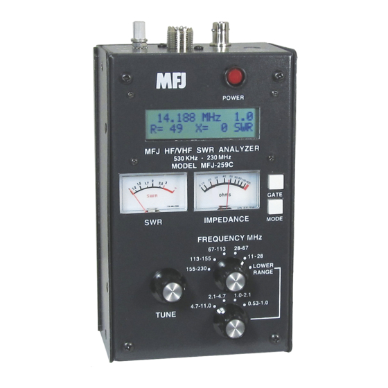
- Page 1 HF/VHF SWR Analyzer Model MFJ-259C INSTRUCTION MANUAL CAUTION: Read All Instructions Before Operating Equipment FMUSER International Group Limited. www.fmuser.net +86 18613072427...
- Page 2 It also measures capacitance, inductance, and serves as a discrete signal generator and frequency counter for the test bench. The MFJ-259C is the latest entry in a long line of time-tested designs using proven technology and rugged construction to ensure years of reliable service.
- Page 3 Display A/D Converter and Processor Meters The MFJ-259C will serve as your eyes and ears when working with RF systems. However, all handheld analyzers share certain limitations, and being aware of them will help you to achieve more meaningful results.
- Page 4 (Gain Reference = 0dB and Phase Shift = 0 degrees). For basic handheld units like the MFJ-259C, the calibration plane is always fixed at the analyzer's RF connector. Any time a transmission line is installed between the analyzer's RF connector and an item being tested, the cable will displace the load from the calibration plane and introduce some form of measurement transformation.
-
Page 5: Power Management
Read this section carefully -- supplying the wrong external voltage or failing to follow battery installation procedures could result in permanent damage! 2.1 External Power Requirements: The MFJ-1312D AC adapter meets all technical requirements for powering the analyzer and it is recommended. Any other external power source must meet the following specifications: •... - Page 6 When SLP is defeated, the message shown below will appear: Power Saving Off Note that SLP is a default function in the MFJ-259C -- it resets automatically each time you power up unless you hold down the Mode key to defeat it. To restore the SLP function at any time during an ongoing test session, simply turn the analyzer Off and then reboot it On again.
- Page 7 See Chapter-4.2 for complete measurement-mode R&X operating instructions. 3.0 VFO Frequency Control The MFJ-259C's expanded-coverage VFO spans the LF, HF, and VHF spectrum from 0.53 MHz (AM broadcast) to 230 MHz (135-cm) in nine bands. 3.1 Band Switching and Tuning: Two Frequency MHz switches select high and low bands.
-
Page 8: Basic Measurement Modes
4.0 Basic Measurement Modes 4.1 The Basic Operating Menu: The MFJ-259C Basic Menu presents the analyzer's most frequently used measurement functions. Tap the Mode switch to step through each one -- or hold it down to scroll through them at a 3-second-per-screen rate. Selections are: 1. - Page 9 MFJ-259C Instruction Manual HF/VHF SWR Analyzer 10.120 MHz R= 73 X=10 [ ] Read Impedance Magnitude (Z) on the analog meter scale. 40 50 70 100 400 0 10 20 Ohms [ ] Read Impedance Magnitude (Z) and Phase Angle ( ) presented numerically by pressing and holding the Gate button.
- Page 10 MFJ-259C Instruction Manual HF/VHF SWR Analyzer As you change VFO frequency, the display will track any change in loss in real time (losses normally increase with frequency). Remember, Loss mode is only accurate for 50-Ohm cable or 50-Ohm devices, and these must be unterminated at the far end.
- Page 11 MFJ-259C Instruction Manual HF/VHF SWR Analyzer capacitive because the reactance exhibited by a capacitor tends to decrease as frequency increases. Standard vs. Measured Values: Even though a Standard Value may be stamped on the case, a capacitor rarely measure that value at RF because of ambient temperature, manufacturing tolerances, and differences in the test frequency.
- Page 12 MFJ-259C Instruction Manual HF/VHF SWR Analyzer Sign Ambiguity: In Inductance mode, the analyzer measures reactance (X) and the operating frequency, and then mathematically computes Inductance in uH. However, the processor can't determine if the reactance sign is positive (+X . When in doubt, tune the VFO up in frequency and see if the value of X increases.
-
Page 13: Advanced Measurements
MFJ-259C Instruction Manual HF/VHF SWR Analyzer [ ] Press Gate again for 1.0-sec gate time: Gate Time 1.0s 146.7000MHz 1.0s Freq. Counter To return to the 0.1-sec default speed, press Gate again. Note that response time to commands entered in the 1.0-sec gate setting is very slow. It may take several seconds for the function to come up initially and several more seconds before it will respond to the command to return to default. - Page 14 MFJ-259C Instruction Manual HF/VHF SWR Analyzer As you enter Advanced mode, keep in mind that all of the same operating limitations and precautions that applied in Basic Menu also apply here. 5.2 Enter Advanced Mode: The Advanced Menu works the same as the Basic Menu, with five functions arranged in sequence.
- Page 15 MFJ-259C Instruction Manual HF/VHF SWR Analyzer minimal compared to forward power. A smaller number (-9.5 dB) equates to higher SWR (~ 2:1) because the difference between forward and reflected power is less. Reflection Coefficient (ρ) expresses the voltage relationship between the reflected wave and the forward wave on a scale of 0 to 1.0.
- Page 16 MFJ-259C Instruction Manual HF/VHF SWR Analyzer 3.8944MHz 3.8944 MHz 1st [ ] Tune the VFO higher in frequency to find the next X=0 null (or close as possible to 0). 11.519 MHz [ ] Press Gate to enter second frequency. Display will show: Dist.
-
Page 17: Adjusting Simple Antennas
6.0 Adjusting Simple Antennas 6.1 General: This chapter focuses on practical tips to help you get the most from your back- yard antennas using the MFJ-259C. To begin, here are some pointers to keep in mind when working with amateur radio antenna system: 1. - Page 18 MFJ-259C Instruction Manual HF/VHF SWR Analyzer reactance into the system. Phase errors compound with multiple half-waves, so it's best to limit length to one or two phase rotations. 2. SWR, Resonance, and Impedance: Always use SWR rather than Resonance (X=0) or Impedance magnitude (Z) to optimize simple antennas.
- Page 19 MFJ-259C Instruction Manual HF/VHF SWR Analyzer at the far end of the cable. If it is elevated or the Impedance (Z) fluctuates very much as you tune the analyzer's VFO, suspect defective cable. 7. Lossy Cable: Coax may exhibit excessive loss from contamination or may have too much normal attenuation for use at higher operating frequencies.
- Page 20 MFJ-259C Instruction Manual HF/VHF SWR Analyzer [ ] Calculate the new (target) antenna length (L ) as follows: L Example: Your 132-foot dipole has minimum SWR at 3.750 Mhz. You want it at 3.900 MHz. The element is presently too long, so: S = 3.750/3.900 = 0.96.
- Page 21 7.0 Special Measurement Procedures 7.1 Overview: There are a number of specialized measurement procedures you can follow to extend the versatility of your MFJ-259C. These include the following tasks: • Measuring and cutting a transmission line stub to Electrical Length.
- Page 22 MFJ-259C Instruction Manual HF/VHF SWR Analyzer If calculations and the Vf accurate, your null should occur ~20% below the target frequency to reflect the added length. Next, calculate a scaling factor to determine exact cut length. You've initially cut the cable 20% "long and low", so your scaling factor will always be less than 1.0: [ ] To find the Scaling Factor (S ), divide the null freq.
- Page 23 MFJ-259C Instruction Manual HF/VHF SWR Analyzer Load = 100 Ohms 50 Ohm SWR = 2:1 R2 (High) R1 (Low) Transmission 100 Ohms 25 Ohms Line ° ° R1 x R2 25 x 100 Z = 50 Ohms Viewed on a Smith Chart, the transformed load impedance (R ±jX) literally traces a circle around the characteristic impedance of the transmission line with each 360-degrees rotation.
- Page 24 7.5 Pre-adjusting Antenna Tuners Using the MFJ-259C to pre-adjust the impedance match through your station's tuner (ATU) avoids exposing the transmitter PA to high-SWR loads and eliminates needless over-the-air interference.
- Page 25 MFJ-259C Instruction Manual HF/VHF SWR Analyzer voltage at the input port generated by the MFJ-259C to the load voltages at the other ports using standard power-level conversions. 7.7 Testing Baluns: To evaluate the performance of "current" and "voltage" style baluns,...
-
Page 26: Technical Assistance
8.0 Technical Assistance If you have any problem with your MFJ-259C, first check the appropriate section of this manual. If the manual does not reference your problem and the problem isn't solved by reading the manual, you may call MFJ Technical Service at 662-323-0549 or the MFJ Factory at 622- 323-5869 . - Page 27 MFJ Enterprises, Inc. warrants to the original owner of this product, if manufactured by MFJ Enterprises, Inc. and purchased from an authorized dealer or directly from MFJ Enterprises, Inc. to be free from defects in material and workmanship for a period of 12 months from date of purchase provided the following terms of this warranty are satisfied.
- Page 28 MFJ-259C Instruction Manual HF/VHF SWR Analyzer switches, jacks, or cables, etc. sent to MFJ Enterprises, Inc. will be returned at the owner's expense unrepaired. Under no circumstances is MFJ Enterprises, Inc. liable for consequential damages to person or property by the use of any MFJ products.
Need help?
Do you have a question about the MFJ-259C and is the answer not in the manual?
Questions and answers