
Summary of Contents for Skytron SS2201-J2
- Page 1 WARMING CABINETS MODELS SS2201-J2 THROUGH SS2207-J2 OWNER'S MANUAL TEC-F-0007 REV8 9/13...
-
Page 3: Table Of Contents
SKYTRON for assistance. Model #_______________________________ Serial #_______________________________ Although current at the time of publication, SKYTRON’S policy of continuous development makes this manual subject to change without notice. J2 WARMING CAB. OWNER'S • REV8... -
Page 4: Product Safety Labels
Page 2 PRODUCT SAFETY LABELS 1-800-759-8766 Manufactured by JAMESTOWN METAL PRODUCTS, INC. MODEL SER. NO. CYCLES VOLTAGE MAX. KWS. MAX. AMPS PHASE EQUIP. NO. F2-012-81 BLANKET WARMER-SAFE OPERATING INSTRUCTIONS 1-ALWAYS DISCONNECT POWER WHEN SERVICING THIS DEVICE TO ELIMINATE RISK OF ELECTRIC SHOCK! 2-Refer to the Operating Manual provided prior to using this device, or anytime you have a question about safe operation. - Page 5 Page 3 LABEL LOCATIONS Technical Data • Capacity • Dimensions - Inches (millimeter) Cubic capacity (Liter capacity) SS2201- SS2205- SS2207- SS2201- SS2205- SS2207- J2(G) J2(G) J2(G) J2(G) J2(G) J2(G) Exterior Total 4.37 ft 17.5 ft 15.72 ft Width 30(762) 30(762) 30(762) Volume (124) (496) (445) Height...
-
Page 6: Special User Attention
Page 4 SPECIAL USER ATTENTION Knowledge of proper procedures is essential to the safe operation of this equipment. The following precautions should be reviewed WARNING by all personnel prior to operating this equipment. Disconnect (power) supply before servicing. WARNING WARNING Indicates a possibility of personal injury. - Page 7 Page 5 MODELS SS2201-J2 SS2201-J2G 15" 380mm 26" 29¼" 660mm 743mm 27" 686mm 235° DOOR SWING 30" 762mm 6½" HINGES ARE 165mm REVERSIBLE FOR OPPOSITE DOOR SWING 26" 15" 660mm 381mm 18½" 23½" 470mm 597mm 19" LEVELING FEET (4) ½"...
- Page 8 Page 6 15" 380mm MODELS SS2205-J2 SS2205-J2G 26" 29¼" 660mm 743mm 27" 686mm 235° DOOR SWING 30" 762mm FRONT SIDE 59" 1499mm 73½" 1867mm 71½" 1816mm HINGES ARE REVERSIBLE FOR OPPOSITE DOOR SWING 19" 2" LEVELING FEET (4) ½" 483mm 50mm 13mm 24"...
- Page 9 Page 7 15" 380mm MODELS SS2207-J2 SS2207-J2G 26" 29¼" 660mm 743mm 27" 686mm 235° DOOR SWING 30" 762mm 6½" 165mm SIDE FRONT 16¼" 15" 413mm 381mm 73½" 1867mm 71½" 1816mm 44" 35¼" 1118mm HINGES ARE 895mm REVERSIBLE FOR OPPOSITE DOOR SWING 19"...
-
Page 10: Section I Introduction
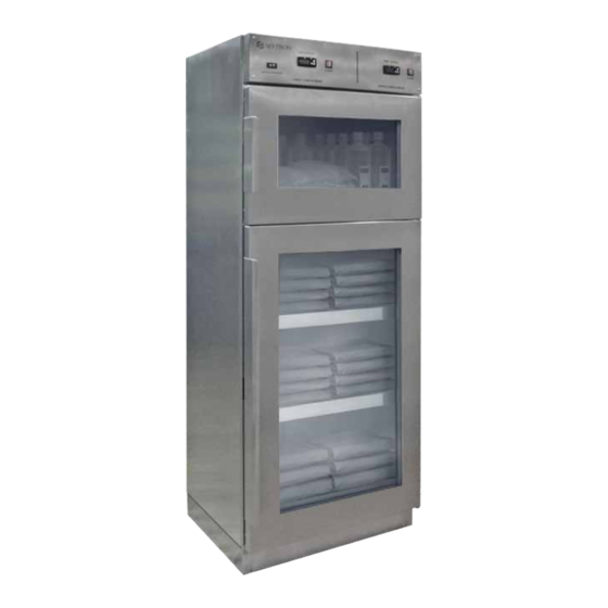
The body of the warming cabinet is double walled ICU, ER and trauma areas. SKYTRON Model stainless steel construction with insulation for SS2201-J2(G) offers a compact size with one increased heating efficiency. Doors are made warming compartment. Model SS2205-J2(G) offers of double paned stainless steel or double paned a full size cabinet with one warming compartment. - Page 11 This equipment contains no user serviceable parts. of the cabinet. To avoid injury, refer all repairs to SKYTRON trained service personnel. e. Remove the shipping brackets holding the shelves in the bottom compartment and discard.
-
Page 12: Section Ii Operation
Page 10 SECTION II OPERATION Control Layout Display Messages POWER ERROR CODE DESCRIPTION DISPLAY SWITCH Memory Error Short-Circuit Probe Error Open Probe Error Initial Operation Initial power up a. Plug the power cord into a properly grounded 120VAC electrical outlet. CIRCUIT UP ARROW b. - Page 13 Page 11 Operating Instructions Bottles should be loaded to allow for a minimum of Turning the warmer on one half inch from the top of the compartment and a. Make sure the power cord is plugged into a spacing around the back and sides one quarter inch and not protrude past the front edge of the fluid tray properly grounded 120VAC electrical outlet.
- Page 14 Reinstall the shelf with the raised edge toward Skytron recommends the use of personal protective the front of the cabinet. equipment while loading and unloading of contents.
-
Page 15: Section Iii Maintenance & Repair
SECTION III MAINTENANCE & REPAIR 3-1. Troubleshooting If your unit is not operating properly, check the following before calling your authorized service agent. Do not attempt to repair or service beyond this point. Contact SKYTRON for nearest authorized service agent. TROUBLESHOOTING GUIDE... - Page 16 Yearly - Temperature Controller Calibration It is recommended to perform preventative 1. Place an independent accurate thermometer maintenance on the Skytron model warming in the chamber and close the door. cabinets every six months or when any service is 2.
- Page 17 2. Remove the fan assembly from the ceiling plenum by removal of four Phillips head a. For models SS2201-J2(G), SS2205-J2(G) screws and unplug the power cord and place and upper chamber of SS2207-J2(G): to the side.
- Page 18 Page 16 3-5. Heating Element and/or Temperature Probe Replacement: The Heating Element and Temperature Probe are 4. The temperature probe is located above the located in the heating plenum and positioned close heating element and held in place with a hold to each other.
- Page 19 14. Check for alignment of the latch keeper to the latch pawl. Adjust the keeper up or down to proper clearance. If the proper clearance cannot be achieved, washers (Skytron part number F1-010-93) or hinge bushings (Skytron part number F1-010-92) may be added to the lower hinge pin of the door to help raise the door to align with the keeper.
- Page 20 Page 18 3-7. Temperature Controller a. Replacement 8. Repeat until all necessary parameters are If a fault is determined in the temperature controller modified. and replacement is required follow the steps 9. Press SET and DOWN at the same time to below to replace the controller.
- Page 21 SKYTRON authorized techniques. Service instructions and parts are service representative using SKYTRON authorized available from SKYTRON. replacement parts and service techniques. Preventive Maintenance contracts are available Warming Cabinet Maintenance Matrix through your local SKYTRON representative.
-
Page 22: Section Iv Replacement Parts
Page 20 SECTION IV REPLACEMENT PARTS J2 WARMING CAB. OWNER'S • REV8... - Page 23 Shown on wiring diagram (pg. 22) S.N. 010801 & Later (Jan. 08 & Later) *** S.N. ending with "M" Parts replaced with other than SKYTRON authorized components may cause damage to the equipment and / or contents. J2 WARMING CAB. OWNER'S • REV8...
-
Page 24: Wiring Diagram
Page 22 WIRING DIAGRAM J2 WARMING CAB. OWNER'S • REV8... - Page 25 That fact should be noted on the Bill of Lading agents is corrected, if the transportation company offered by the transportation company. An example does not honor the claim, as long as SKYTRON of an applicable statement would be; "Received in receives the full cooperation of the consignee in good order except as noted"...
- Page 28 5085 Corporate Exchange Blvd. S.E. Grand Rapids, MI 49512 • 1.616.656.2900 • FAX 1.616.656.2906...
Need help?
Do you have a question about the SS2201-J2 and is the answer not in the manual?
Questions and answers