
Related Manuals for BMW M57


Summary of Contents for BMW M57
- Page 1 Diesel Engines M57/M67 Common Rail Course contents/Background material Information status: 09/98 Service Training...
-
Page 2: Table Of Contents
DI Diesel Engines M57/M67 - Common Rail Sec. 1-10 Course contents/Background material Contents Page Sec. 1 Introduction Concepts Engine views Technical features DDE control unit Technical data Exhaust emission legislation Notes on exhaust emission standards/ test cycles Sec. 2 Engine components... - Page 3 DI Diesel Engines M57/M67 - Common Rail Sec. 1-10 Course contents/Background material Sec. 4 Engine mounts Brief description Requirements and Objectives System structure Component description Hydraulic mount Functional description DDE parameters Vacuum supply Sec. 5 Lubrication system Brief description Requirements and Objectives...
- Page 4 DI Diesel Engines M57/M67 - Common Rail Sec. 1-10 Course contents/Background material Sec. 7 Fuel system Brief description of function Requirements and objectives System structure Component description Fuel tank Advance delivery pump Auxiliary delivery pump Fuel filter Inlet pressure sensor...
- Page 5 DI Diesel Engines M57/M67 - Common Rail Sec. 1-10 Course contents/Background material Sec. 9 Digital Diesel Electronics Review of DDE control units System structure Signal description Analog inputs Digital inputs Frequency inputs Power output stages Switching outputs Signal output stages, bi-directional interfaces...
-
Page 6: Introduction
KT-3692 Fig. 1: Competitive situation M47/M57 Initially, the new M57 engine will be installed in the form of a top- of-the-range diesel engine in the 5 and 7 Series. The M67 will enhance the top end of the diesel engine range in the 7 Series. - Page 7 Objectives The layout and design particularly of the six-cylinder engine is based on the following primary objectives: • The creation of a top-of-the-range diesel engine for all BMW model series • Maintaining the leading competitive position with regard to output power and torque development as well as comfort in the entire diesel vehicle segment •...
-
Page 8: Concepts
DI Diesel Engines M57/M67 - Common Rail Sec. 1 P.3 Course contents/Background material Concepts The concept features of the new engines correspond to those of second generation DI diesel engines. The advantages in fuel consumption offered by the first series-... -
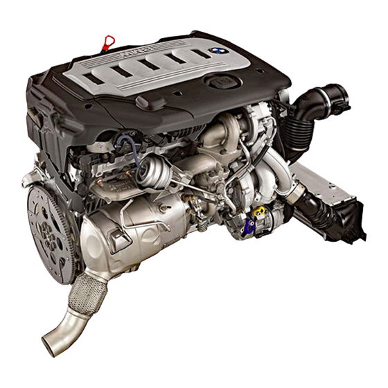
Page 9: Engine Views
DI Diesel Engines M57/M67 - Common Rail Sec. 1 P.4 Course contents/Background material Engine views Fig. 3: M57 engine - General view KT-3748 KT-3754 Fig. 4: M57 engine - Sectional view © BMW AG, Service Training... - Page 10 DI Diesel Engines M57/M67 - Common Rail Sec. 1 P.5 Course contents/Background material Dummy-Graphik Graphic currently not available. KT-1463 Fig. 5: M67 engine - General view Dummy-Graphik Graphic currently not available. KT-1463 Fig. 6: M67 engine - Sectional views © BMW AG, Service Training...
-
Page 11: Technical Features
DI Diesel Engines M57/M67 - Common Rail Sec. 1 P.6 Course contents/Background material Technical features Common features • Light-alloy cylinder head • 4-valve technology with centrally arranged injection nozzle • Valves and springs identical to M47 • Exhaust turbocharger with variable nozzle turbine (VNT) •... -
Page 12: Dde Control Unit
Different control units are used depending on the type of engine: • M57 - DDE 4 (different characteristic maps for E38/E39) • M67 - DDE 4.1 Technical data The data of the new M57 and M67 engines are as follows: Engine type/valves R6/4 V90-8/4 Displacement (eff.) - Page 13 DI Diesel Engines M57/M67 - Common Rail Sec. 1 P.8 Course contents/Background material Typprüfwerte M57 / Md=390 Mn Md=390 Mn bea t175 0rpmn beia4t000 U/min PP=135KK W 4000 rpm zahl (U/min) 1000 1500 2000 2500 3000 3500 4000 4500 5000...
-
Page 14: Exhaust Emission Legislation
DI Diesel Engines M57/M67 - Common Rail Sec. 1 P.9 Course contents/Background material Exhaust emission legislation Pollutant limits have been further reduced in exhaust emission guidelines. These limits for EU-3 will come into force as from 01.01.2000 for new type approvals. -
Page 15: Notes On Exhaust Emission Standards/Test Cycles
DI Diesel Engines M57/M67 - Common Rail Sec. 1 P.10 Course contents/Background material Notes on exhaust emission standards/test cycles EU-3 D • Since 01.07.97 in Germany only (for tax reasons) • Testing at room temperature 20 - 30 ºC • Cold run (40 sec. idling speed without measurement, conditioning) •... -
Page 16: Engine Components
• Pistons with rings and pins • Chain drive • Oil pan • Timing case cover KT-3749 Fig. 10: Engine components and add-on parts - M57 Differences between the components for the M57 and M67 engines are listed separately. © BMW AG, Service Training... -
Page 17: Component Description
The engine block represents the central component of the power plant. It houses the crankshaft, connecting rods and pistons. The following features apply both to the M57 and M67: • Crankshaft position/rpm sensor mounted on crankcase for radial sensing at inner incremental wheel (last crankshaft web) •... - Page 18 DI Diesel Engines M57/M67 - Common Rail Sec. 2 P.3 Course contents/Background material M67-specific features • Cast starter flange on both sides, cast timing case • Integrated water flow control to water pump • Oil supply gallery for oil spray nozzles with central pressure control valve •...
- Page 19 DI Diesel Engines M57/M67 - Common Rail Sec. 2 P.4 Course contents/Background material Forward direction 1 - Cracked bearing cap KT-3714 Fig. 13: Engine block - view M67 (from below) • Cracked bearing caps • V-engine-compliant threaded connection of main bearing...
-
Page 20: Cylinder Head Gasket
DI Diesel Engines M57/M67 - Common Rail Sec. 2 P.5 Course contents/Background material Cylinder head gasket The cylinder head gasket seals off the transition points between the engine block and cylinder head. • Multi-layer steel gasket • Water flow cross-sections adapted (cylinder-specific) to requirements facilitating uniform coolant flow •... -
Page 21: Cylinder Head
The cylinder head represents the upper limit of the combustion chamber. It accommodates the necessary valve timing elements (valves, injectors, camshafts). The following features apply both to the M57 and M67: • Cast aluminium, cast timing case • Coolant flow from exhaust to inlet side •... - Page 22 DI Diesel Engines M57/M67 - Common Rail Sec. 2 P.7 Course contents/Background material M67-specific features • Inlet port configuration (1 swirl/1 tangential port), twin-port arrangement 1 - Exhaust ports 2 - Swirl port (inlet) 3 - Tangential port (inlet) 4 - Glow (heater) plug KT-3715 Fig.
-
Page 23: Cylinder Head Cover
Cylinder head cover The cylinder head cover combines the oil separator and intake silencer in the intake module system. The following feature applies both to the M57 and M67: • Mounting on cylinder head by means of decoupling elements M57-specific features •... - Page 24 DI Diesel Engines M57/M67 - Common Rail Sec. 2 P.9 Course contents/Background material M67-specific features • Aluminium casing • Integrated oil separator, preliminary separation by means of cyclone separator, fine separation with threaded winding downstream Forward direction 1 - Cylinder head cover...
-
Page 25: Valve Gear
Course contents/Background material Valve gear The valve gear consists of the camshafts, rocker arms as well as valves and springs. The following features apply both to the M57 and M67: Camshaft • Chilled cast iron • New inlet and exhaust camshafts •... - Page 26 DI Diesel Engines M57/M67 - Common Rail Sec. 2 P.11 Course contents/Background material M57-specific features • Vacuum pump driven by front of exhaust camshaft M67-specific features • Vacuum pump driven by front of inlet camshafts 1 - 4 Technical data: Valve diameter 25.9...
-
Page 27: Crankshaft
Crankshaft The crankshaft converts the linear stroke motion of the pistons into rotary motion. The following features apply both to the M57 and M67: • Threaded connection on front end of crankshaft designed as 4-hole mounting (replaces central bolt) • Thrust bearing designed as constructed bearing M57-specific features •... - Page 28 DI Diesel Engines M57/M67 - Common Rail Sec. 2 P.13 Course contents/Background material M67-specific features • Material 42 CrMo 4, nitrocarburized • Shaft cranked at two levels (similar to M62) • Main bearing, common part with M62 • Thrust bearing with integrated bearing, arranged on flywheel...
-
Page 29: Flywheel
DI Diesel Engines M57/M67 - Common Rail Sec. 2 P.14 Course contents/Background material Flywheel The flywheel is located between the engine and gearbox. The task of the flywheel is to increase the rotating mass so as to enable more uniform rotary motion. -
Page 30: Connecting Rods With Bearings
The connecting rod connects the piston to the crankshaft. Each connecting rod is mounted such that it can rotate. The following features applies both to the M57 and M67: • Big-end bearing half on connecting rod end designed as sputter bearing M57-specific features •... - Page 31 DI Diesel Engines M57/M67 - Common Rail Sec. 2 P.16 Course contents/Background material Technical data: Distance between hole centres 30.0 Piston pin (gudgeon pin) diameter Crankshaft diameter Cracked connecting rods 57.6 © BMW AG, Service Training...
-
Page 32: Pistons With Rings And Pins
The following features apply both to the M57 and M67: • Cooling duct piston with rotationally symmetrical piston crown bowl specific to DI common rail •... -
Page 33: Chain Drive
In this way it defines the interaction between the stroke motion of the piston and the movements of the valves. The following features apply both to the M57 and M67: • 2-piece chain drive • Tensioning rail made from aluminium die casting with plastic slide lining •... - Page 34 DI Diesel Engines M57/M67 - Common Rail Sec. 2 P.19 Course contents/Background material M67-specific features • Chain drive 1: From crankshaft to inlet camshaft, bank 1 (cyls. 1 - 4) • Chain drive 2: From crankshaft to inlet camshaft, bank 2 (cyls.
-
Page 35: Oil Pan
• Return flow pipe (E38) so that oil from the oil separator can return to the oil sump below the oil level (blow-by gases) O-ring Oil return pipe from oil separator Forward direction KT-3710 Fig. 26: Oil pan - M57 in E38 © BMW AG, Service Training... - Page 36 Sec. 2 P.21 Course contents/Background material Forward direction KT-3709 Fig. 27: Oil pan - M57 in E39 M67-specific features • Two-piece casing • Upper section made of pressure die cast aluminium with integrated thermal oil level sensor, sheet metal bottom section (common part with M62) •...
-
Page 37: Timing Case Cover (M57)
Sec. 2 P.22 Course contents/Background material Timing case cover (M57) On the M57 the timing case cover covers the chain drive in the area of the crankcase. On the M67 this cover is integrated in the crankcase. • Aluminium die casting •... -
Page 38: Ancillary Components And Belt Drive
DI Diesel Engines M57/M67 - Common Rail Sec. 3 P.1 Course contents/Background material Ancillary components and belt drive Brief description Various ancillary components are driven by the crankshaft of the engine with the aid of one or two drive belts. -
Page 39: System Structure
DI Diesel Engines M57/M67 - Common Rail Sec. 3 P.2 Course contents/Background material System structure The belt drive consists of following components: • Torsional vibration damper • Starter motor • Alternator • A/C compressor • Belts • Tensioning pulleys or one idler pulley... - Page 40 DI Diesel Engines M57/M67 - Common Rail Sec. 3 P.3 Course contents/Background material 1 - Torsional vibration damper 4 - A/C compressor 2 - Tensioning pulley 5 - Water pump 3 - Power steering pump 6 - Alternator (water-cooled) KT-3693 Fig.
-
Page 41: Component Description
Sec. 3 P.4 Course contents/Background material Component description Torsional vibration damper The M57 and M67 both feature an adaptive (engine-specific) vibration damper with decoupled belt pulley. Torsional vibration damper M57 E38/E39 • Dual damper adapted specifically to type of engine •... -
Page 42: Starter Motor
DI Diesel Engines M57/M67 - Common Rail Sec. 3 P.5 Course contents/Background material Torsional vibration damper M67 E38 • Trosional vibration damper with decoupled pulley • Mounting with 4 central bolts (tightening torque 45 Nm) Starter motor Starter M57 E38/E39 •... -
Page 43: Alternator
DI Diesel Engines M57/M67 - Common Rail Sec. 3 P.6 Course contents/Background material Alternator (also refer to TLF TA3 M51 TÜ) Alternator M57 E38/E39 (as on M51) • Basic compact alternator 95 A with start load response • Special version 140 A alternator with load response Alternator M67 E38 •... -
Page 44: Tensioning Pulley Or Idler Pulley
DI Diesel Engines M57/M67 - Common Rail Sec. 3 P.7 Course contents/Background material Tensioning pulley or idler pulley The tensioning pulley is designed as a spring-loaded element, thus rendering the hydraulic connection (M47) unnecessary. The idler pulley arranged on the alternator ensures the belt drive runs more smoothly. -
Page 45: Engine Mounts
Course contents/Background material Engine mounts Brief description The engine mount principle used on the M57 and M67 engines basically the same as from the M51TÜ. The damping charac teristics of the hydraulic mount are set softer or harder by means of a vacuum. In this way, the vibration transmitted from the engine to the body can be influenced specifically. -
Page 46: System Structure
DI Diesel Engines M57/M67 - Common Rail Sec. 4 P.2 Course contents/Background material System structure The system consists of: • Two hydraulic mounts with controlled damping characteristics • One electric changeover valve • The control unit (DDE) • Various electrical and pneumatic lines KT-172 Fig. -
Page 47: Component Description
DI Diesel Engines M57/M67 - Common Rail Sec. 4 P.3 Course contents/Background material Component description Hydraulic mount The damping-controlled hydraulic mount consists of: • One conventional hydraulic mount • One control unit The hydraulic mount with controlled damping characteristics operates by way of vacuum. - Page 48 DI Diesel Engines M57/M67 - Common Rail Sec. 4 P.4 Course contents/Background material The force exerted by the spring is reduced by applying vacuum to the control unit of the mount (12) so that a bypass now opens permanently. The hydraulic fluid can now flow back and forth via larger cross section between the two chambers.
-
Page 49: Functional Description
DI Diesel Engines M57/M67 - Common Rail Sec. 4 P.5 Course contents/Background material Functional description The vacuum necessary to activate the mounts is taken from a distributor in the vacuum line between the vacuum pump and brake booster. Vacuum is applied simultaneously to both mounts when idling and in the speed range close to idling. -
Page 50: Vacuum Supply
DI Diesel Engines M57/M67 - Common Rail Sec. 4 P.6 Course contents/Background material Vacuum supply The necessary volumetric flow is taken from the vacuum line between the vacuum pump and brake booster. For this purpose, the vacuum line of the damping-controlled hydraulic mount is connected to the long outlet of the distributor. -
Page 51: Lubrication System
Sec. 5 P.1 Course contents/Background material Lubrication system Brief description The lubrication system of the M57 corresponds to that of the M47. Geometric adaptations and optimisation measures have been implemented. Requirements and Objectives The lubrication system must meet the following requirements and objectives: •... -
Page 52: System Structure
DI Diesel Engines M57/M67 - Common Rail Sec. 5 P.2 Course contents/Background material System structure The lubrication system consists of following components: • Oil pan with dipstick (see engine components) • Oil pump • Oil filter with integrated oil-to-water heat exchanger •... - Page 53 DI Diesel Engines M57/M67 - Common Rail Sec. 5 P.3 Course contents/Background material 1 - Oil pump 10 - Piston spray nozzle 2 - Oil intake pipe 11 - Oil pressure control valve 3 - Unfiltered oil duct before filter...
-
Page 54: Component Description
DI Diesel Engines M57/M67 - Common Rail Sec. 5 P.4 Course contents/Background material Component description Oil pump Oil pump M57 E38/E39 • Oil pump arranged in oil pan • Chain drive KT-3847 Fig. 38: Oil pump M57 © BMW AG, Service Training... - Page 55 DI Diesel Engines M57/M67 - Common Rail Sec. 5 P.5 Course contents/Background material Oil pump M67 E38 • Duocentric pump • Arranged at bottom of engine block • Chain drive • Intake snorkel in oil pan KT-3848 Fig. 39: Oil pump M67...
-
Page 56: Oil Filter With Integrated Oil-To-Water Heat Exchanger
• In the same way as on the M47, the water outlet is located on the oil-to-water heat exchanger 1 - Oil filter housing with filter element 2 - Oil pressure sensor 3 - Oil-to-water heat exchanger KT-3675 Fig. 40: Oil module M57 E38/E39 (with oil-to-water heat exchanger) © BMW AG, Service Training... -
Page 57: Oil Spray Nozzles
DI Diesel Engines M57/M67 - Common Rail Sec. 5 P.7 Course contents/Background material Oil filter with oil-to-water heat exchanger M67 E38 • Mounted directly in V-area of cylinder block • Oil-to-water heat exchanger located in water bath of V-area 1 - Oil filter housing with filter element... -
Page 58: Cooling System
Brief description The coolant circuit is designed to provide long-term protection against frost and corrosion. The design of the M57 is identical to that of the M51 and in the M67 to that of the M62. The cooling system has been adapted to the new requirements concerning the cooling capacity and the modified environment (common rail, injection system). -
Page 59: System Structure
• Radiator • Fan/shroud • Auxiliary heater • Independent park heating option ÖWWT KT-3867 Fig. 43: M57 - Coolant circuit with auxiliary heater ÖWWT KT-3868 Fig. 44: M57 - Coolant circuit with independent park heating option © BMW AG, Service Training... - Page 60 DI Diesel Engines M57/M67 - Common Rail Sec. 6 P.3 Course contents/Background material EGR cooler ÖWWT EGR cooler KT-3869 Fig. 45: M67 - Coolant circuit with auxiliary heater EGR cooler ÖWWT EGR cooler KT-3870 Fig. 46: M67 - Coolant circuit with independent park heating option...
-
Page 61: Component Description
Course contents/Background material Component description Water pump The water pumps for the M57 and M67 are arranged on the end face of the crankcase. • Thermostat integrated in water pump housing • Leakage is directed through drainage tubes into the pulley KT-3880 Fig. -
Page 62: Radiator
• M57 E38/E39 approx. 9.2 litre • M67 E38 approx. 16.0 litre Power steering cooling loop Gear oil cooler Assembly frame A/C- condenser Intercooler KT-3865 Fig. 48: Arrangement of cooling assembly - rear view M57 E39/E38 © BMW AG, Service Training... - Page 63 Fan shroud Viscous fan Intercooler KT-3864 Fig. 49: Arrangement of cooling assembly - rear view M57 M67-specific features • Expansion tank integrated in fan shroud • 5 back-up flaps integrated in fan shroud • The AUC sensor located above the centre of the fan shroud.
-
Page 64: Exhaust Hood/Shutter
Course contents/Background material Exhaust hood/shutter No radiator shutters are currently installed in the M57 and M67. The M57 and M67 feature a 7-blade plastic fan driven by a viscous clutch. Compared to an electric fan, the viscous fan provides better cooling capacity.
Need help?
Do you have a question about the M57 and is the answer not in the manual?
Questions and answers