
Related Manuals for Hyster J30XNT


Summary of Contents for Hyster J30XNT
- Page 1 OPERATING MANUAL J30-40XNT (K160) DO NOT REMOVE THIS MANUAL FROM THIS UNIT PART NO. 1676236 2/17...
- Page 2 STEERING TIRE SIZE SPECIAL EQUIPMENT OR ATTACHMENTS © Hyster Company 2017. All Rights Reserved. HYSTER, , FORTIS, MONOTROL, and YARDMASTER are Registered Trademarks of Hyster-Yale Group, Inc. HSS, DURAMATCH, UNISOURCE, and are Trademarks in the United States and certain other jurisdictions.
-
Page 3: Foreword
NOTE: A comprehensive operator training program is avail- 12/98, in the proper operation of THIS lift truck. able from Hyster Company. For further details, contact your dealer for Hyster lift trucks. • Understand the capabilities and limitations of the lift truck. - Page 4 Foreword Additional information that describes the safe operation NOTE: Hyster lift trucks are not intended for use on public and use of lift trucks is available from the following sources: roads. • Employment safety and health standards or regulations NOTE: The following symbols and words indicate safety (Examples: "Occupational Safety and Health Standards...
-
Page 5: Table Of Contents
Contents Contents Foreword ..............Impact Sensor ............82 TO OWNERS, USERS, AND OPERATORS: ..... INSPECTION BEFORE OPERATION ......83 Warning ................ Checks With the Key or Keyless Switch OFF ... 83 Model Description ............10 Operator Passwords ..........84 GENERAL ..............11 Operator Checklist ............ - Page 6 Contents Lift Trucks with Software Versions 4.32 and How to Raise the Steer Tire ........140 Greater ............. 113 HOW TO CLEAN A LIFT TRUCK ....... 142 Optional Operator Presence System ......114 Maintenance Schedule ..........142 Lift Trucks with Software Versions 4.32 and Maintenance Procedures Every 8 Hours or Daily ..
- Page 7 Contents Telescopic Feature ..........183 Tire Removal, Two-Piece Wheel ......205 Battery Check ............184 Tire Removal, Three- and Four-Piece Wheels ..206 HOW TO MAKE CHECKS WITH THE KEY OR Install the Wheel in the Tire ........207 KEYLESS SWITCH ON ..........185 Install Wheel in Tire, Three- or Four-Piece Wheel ..
- Page 8 Contents PREPARATION FOR USE ......... 221 CHANGES TO THE OVERHEAD GUARD ....221 Preparation After Transport ........221...
-
Page 9: Warning
• INSPECT truck before use. KNOW YOUR LOADS: • DO NOT operate if truck needs repair. Tag truck and remove key. Repair truck before use. Always use Hyster • HANDLE only stable loads within specified weight and Approved parts when making repairs. Replacement load center. - Page 10 Warning WARNING FAILURE TO FOLLOW THESE INSTRUCTIONS CAN CAUSE SERIOUS INJURY OR DEATH! AUTHORIZED, TRAINED OPERATOR ONLY! KNOW THE AREA: • DO NOT use truck to lift people unless there is no other practical option. Then, use only a securely attached spe- •...
- Page 11 Warning WARNING FAILURE TO FOLLOW THESE INSTRUCTIONS CAN CAUSE SERIOUS INJURY OR DEATH! AUTHORIZED, TRAINED OPERATOR ONLY! PROTECT YOURSELF, FASTEN YOUR SEAT BELT! • LIFT or LOWER with mast vertical or tilted slightly back. Use minimum tilt when stacking elevated loads. •...
-
Page 12: Model Description
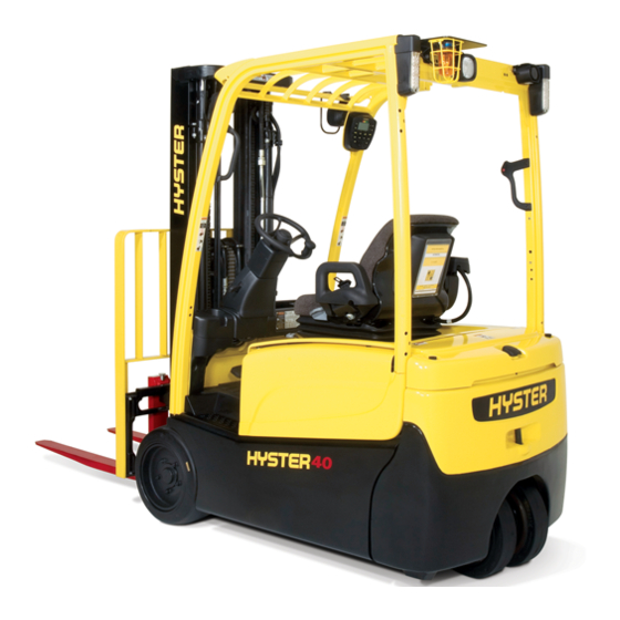
Model Description Model Description OVERHEAD GUARD COUNTERWEIGHT STEER WHEELS DRIVE WHEELS MAST FORKS CARRIAGE LOAD BACKREST EXTENSION OPERATOR SEAT SEAT BELT AND HIP RESTRAINT Figure 1. Major Components of the Lift Truck... -
Page 13: General
See Figure 2 and Figure 3. models: (see Figure 1). In addition to dual, hydraulically-operated, wet disc service J30XNT, J35XNT, and J40XNT (K160) brakes and electrically-operated disc parking brake, the lift trucks covered in this Operating Manual are equipped with The lift trucks covered in this Operating Manual are equip- electric braking (plugging) and an auto brake feature. - Page 14 Model Description HYDRAULIC FILTER HYDRAULIC BREATHER CAP/ DIPSTICK HYDRAULIC TANK HYDRAULIC PUMP MOTOR LEFT TRANSMISSION TRACTION MOTORS RIGHT TRANSMISSION Figure 2. Motor Locations, Lift Trucks Manufactured Before November, 2014...
- Page 15 Model Description HYDRAULIC FILTER HYDRAULIC BREATHER CAP/ DIPSTICK HYDRAULIC TANK HYDRAULIC PUMP MOTOR LEFT TRANSMISSION TRACTION MOTORS RIGHT TRANSMISSION Figure 3. Motor Locations, Lift Trucks Manufactured After November, 2014...
- Page 16 Model Description A brake pedal actuates the hydraulic service brakes at the All lift trucks are equipped with a Battery Discharge Indica- drive wheels. tor (BDI) and an hourmeter. The bar graph type of BDI shows the state of charge of the battery. These lift trucks The lift trucks covered in this Operating Manual can be have Liquid Crystal Display (LCD) screen.
- Page 17 Model Description E-HYDRAULIC CONTROL MINI-LEVERS MANUAL HYDRAULIC CONTROL LEVERS Figure 4. Direction Control Switch...
- Page 18 Model Description The electric lift trucks described in this manual are equip- The full suspension swivel seat option allows the operator ped with a standard, non-swivel seat or a full suspension to better see where he is going when driving the lift truck in swivel seat.
- Page 19 Model Description Figure 5. Seat Components...
-
Page 20: Operator Protection Equipment
Model Description Legend for Figure 5 STANDARD, NON-SWIVEL SEAT FULL SUSPENSION SWIVEL SEAT SEAT BELT BACKREST ANGLE ADJUSTMENT LEVER WEIGHT ADJUSTMENT KNOB HIP RESTRAINT BRACKET RIDE POSITION INDICATOR SWIVEL LATCH RELEASE LEVER FORWARD/BACKWARD ADJUSTMENT LEVER Operator Protection Equipment The hood can be raised for access to the battery. A gas spring helps raise and hold the hood in the up position. -
Page 21: Nameplate
This seat belt is used with the Optional Opera- backrest extension that is different from the one installed tor Presence System. on your truck is required, contact your dealer for Hyster lift The SEAT BELT and HIP RESTRAINTS provide additional trucks. -
Page 22: Safety Labels
Nameplate is covered by the labels shown in Figure 6. If your lift truck has this type of label, do not operate the lift NAMEPLATE truck. Contact your dealer for Hyster lift trucks to obtain a NOTICE LABEL complete Nameplate. - Page 23 Model Description Figure 7. Warning Labels (Sheet 1 of 3)
- Page 24 Model Description Figure 7. Warning Labels (Sheet 2 of 3)
- Page 25 Model Description Figure 7. Warning Labels (Sheet 3 of 3)
-
Page 26: Operator Controls
Model Description Legend for Figure 7 OPERATOR WARNING MAST WARNING PINCH POINTS BATTERY DISCONNECT NO RIDERS NAMEPLATE TIPOVER WARNING UNITS WITH SEAT BELTS BATTERY SPACER MAST WARNING OVERHEAD GUARD IMPACT RATING Operator Controls ately. Injury to personnel can occur if the levers or pedals do not operate as described in the following (See Figure 8, Figure 9, and Table 1) table. - Page 27 Model Description Figure 8. Operator Controls - Manual Hydraulic Controls...
- Page 28 Model Description Figure 9. Operator Controls - Electro-Hydraulic Controls...
- Page 29 Model Description Table 1. Operator Controls (See Figure 8 and Figure 9) Item No. Item Function Horn Button Push the horn button to warn pedestrians and others when approaching intersections and other blind areas. If lift truck is equipped with E-Hydraulic controls, there is another horn button located on the armrest.
- Page 30 Model Description Table 1. Operator Controls (See Figure 8 and Figure 9) (Continued) Item No. Item Function Key Switch and WARNING Keyless Switch The ignition switch is a reed switch which uses an applied mag- netic field. If a strong magnet is placed near the ignition switch, it may not function properly (such as not shutting off power).
- Page 31 Model Description Table 1. Operator Controls (See Figure 8 and Figure 9) (Continued) Item No. Item Function Light Switches There is a rocker switch for each of the following light functions: Front Driving/Brake/Reverse/Parking lights. Rear Driving light and the Strobe light or sometimes Strobe light only.
- Page 32 Model Description Table 1. Operator Controls (See Figure 8 and Figure 9) (Continued) Item No. Item Function Lift/Lower Control Lever NOTE: Manual hydraulic control levers are standard on the trucks covered in this manual. Electronic hydraulic mini-levers are available as an optional control feature for the hydraulic functions. To enable the operation of the hydraulic functions, the operator must be on the seat and the seat belt should be fastened.
- Page 33 Model Description Table 1. Operator Controls (See Figure 8 and Figure 9) (Continued) Item No. Item Function Tilt Control Lever NOTE: Manual hydraulic control levers are standard on the trucks covered in this manual. Electronic hydraulic mini-levers are available as an optional control feature for the hydraulic functions. To enable the operation of the hydraulic functions, the operator must be on the seat and the seat belt should be fastened.
- Page 34 Model Description Table 1. Operator Controls (See Figure 8 and Figure 9) (Continued) Item No. Item Function Tilt Control Lever (Cont) The RTST option automatically stops the tilt function at a set point. To override the RTST option: • For lift trucks equipped with e-hydraulic mini-levers, press the override button located directly behind the tilt mini-lever and push the tilt mini-lever forward or pull backward.
- Page 35 Model Description Table 1. Operator Controls (See Figure 8 and Figure 9) (Continued) Item No. Item Function Manual Control Lever for Auxiliary NOTE: Manual hydraulic control levers are standard on the trucks Hydraulic Functions (3rd Lever) covered in this manual. Electronic hydraulic mini-levers are available as an optional control feature for the hydraulic functions.
- Page 36 Model Description Table 1. Operator Controls (See Figure 8 and Figure 9) (Continued) Item No. Item Function Manual Control Lever for Auxiliary NOTE: If truck is equipped with a three function control valve, three Hydraulic Functions (3rd Lever) levers and clamp attachment, the last (3rd) lever controls clamp func- tions.
- Page 37 Model Description Table 1. Operator Controls (See Figure 8 and Figure 9) (Continued) Item No. Item Function Electronic Control Mini-Lever for Auxiliary NOTE: To operate the mini-levers, the operator must be on the seat. Hydraulic Functions (3rd Mini-Lever) For lift trucks equipped with optional operator presence system, the operator mist be on the seat and the seat belt must be fastened.
- Page 38 Model Description Table 1. Operator Controls (See Figure 8 and Figure 9) (Continued) Item No. Item Function Electronic Control Mini-Lever for Auxiliary NOTE: If truck is equipped with a three function control valve, three Hydraulic Functions (3rd Lever) (Cont) mini-levers and clamp attachment, the last (3rd) lever controls clamp functions.
- Page 39 Model Description Table 1. Operator Controls (See Figure 8 and Figure 9) (Continued) Item No. Item Function Manual Control Lever for Auxiliary NOTE: Manual hydraulic control levers are standard on the trucks Hydraulic Functions (4th lever) covered in this manual. Electronic hydraulic mini-levers are available as an optional control feature for the hydraulic functions.
- Page 40 Model Description Table 1. Operator Controls (See Figure 8 and Figure 9) (Continued) Item No. Item Function Manual Control Lever for Auxiliary NOTE: If truck is equipped with four function control valve, four lev- Hydraulic Functions (4th lever) ers and clamp attachment, the last (4th) lever controls clamp func- tions.
- Page 41 Model Description Table 1. Operator Controls (See Figure 8 and Figure 9) (Continued) Item No. Item Function Electronic Control Mini-Lever for Auxiliary NOTE: To operate the mini-levers, the operator must be on the seat. Hydraulic Functions (4th mini-lever) For lift trucks equipped with optional operator presence system, the operator mist be on the seat and the seat belt must be fastened.
- Page 42 Model Description Table 1. Operator Controls (See Figure 8 and Figure 9) (Continued) Item No. Item Function Electronic Control Mini-Lever for Auxiliary NOTE: If truck is equipped with four function control valve, four mini- Hydraulic Functions (4th mini-lever) levers and clamp attachment, the last (4th) mini-lever controls clamp functions.
- Page 43 Model Description Table 1. Operator Controls (See Figure 8 and Figure 9) (Continued) Item No. Item Function Electronic Control Mini-Lever for Auxiliary NOTE: If truck is equipped with five function control valve, four mini- Hydraulic Functions (4th mini-lever) levers and clamp attachment, the 4th mini-lever controls clamp func- tion and the 3rd mini-lever controls the 3rd and 5th functions.
- Page 44 Model Description Table 1. Operator Controls (See Figure 8 and Figure 9) (Continued) Item No. Item Function Emergency Disconnect Switch The emergency disconnect switch, on trucks equipped with manual (manual levers) levers, is located behind the levers. The operator can disconnect all electrical power to the lift truck by pushing the emergency disconnect switch down until it clicks.
- Page 45 Model Description Table 1. Operator Controls (See Figure 8 and Figure 9) (Continued) Item No. Item Function Emergency Disconnect Switch The emergency disconnect switch, on trucks equipped with E- (E-Hydraulics) Hydraulic mini-levers, is located on the right side of the armrest. The operator can disconnect all electrical power to the lift truck by pushing the emergency disconnect switch in until it clicks.
- Page 46 Model Description Table 1. Operator Controls (See Figure 8 and Figure 9) (Continued) Item No. Item Function MONOTROL® Pedal When the lift truck is equipped with a MONOTROL® pedal, the direc- tion and the speed of travel is controlled by the MONOTROL® pedal. When the right (REVERSE) side of the pedal is pushed, the lift truck will move in the reverse direction.
- Page 47 Model Description Table 1. Operator Controls (See Figure 8 and Figure 9) (Continued) Item No. Item Function Automatic Parking Brake Manual The truck may be equipped with an optional Automatic Parking Brake Override Handle (Optional) (APB). The APB will apply a brake to the traction motor after lift truck stops.
- Page 48 Model Description Table 1. Operator Controls (See Figure 8 and Figure 9) (Continued) Item No. Item Function Steering Column Tilt Memory Lever Lift the tilt position lever to adjust the steering column up or down for (Optional) the operator's comfort. This tilt memory lever permits moving the steering column from a locked position to an upright position and back to the original locked position.
- Page 49 Model Description Table 1. Operator Controls (See Figure 8 and Figure 9) (Continued) Item No. Item Function Direction Control Switch The direction control switch is used on some lift trucks. When the lift truck is equipped with a direction control switch, it will also have an accelerator pedal instead of a MONOTROL®...
- Page 50 Model Description Table 1. Operator Controls (See Figure 8 and Figure 9) (Continued) Item No. Item Function Armrest Adjustment Handles, Lift Trucks The armrest on lift trucks equipped with E-Hydraulic mini-levers, is With E-Hydraulic Controls adjustable for operator comfort. (Not Shown in Figure 9) The large adjustment handle on the lower part of the slide assembly, moves the armrest up and down in a diagonal direction, to adjust the height of the armrest.
- Page 51 Model Description Table 1. Operator Controls (See Figure 8 and Figure 9) (Continued) Item No. Item Function Hood Latch, NOTE: Before raising the hood, move the steering column to the for- Lift Trucks Manufactured Before Novem- ward position and slide the seat all the way back. For lift trucks ber, 2014 equipped with Rapid/Fast Charging, slide the seat all the way for- (Not Shown in Figure 8 and Figure 9)
- Page 52 Model Description Table 1. Operator Controls (See Figure 8 and Figure 9) (Continued) Item No. Item Function Hood Latch, NOTE: Before raising the hood, move the steering column to the for- Lift Trucks Manufactured After November, ward position and slide the seat all the way back. For lift trucks 2014 equipped with Rapid/Fast Charging, slide the seat all the way for- (Not Shown in Figure 8 and Figure 9)
- Page 53 Model Description Table 1. Operator Controls (See Figure 8 and Figure 9) (Continued) Item No. Item Function Battery Connector CAUTION (Not Shown in Figure 8 and Figure 9) Make sure both halves of the connectors are the same type and color.
- Page 54 Model Description Table 1. Operator Controls (See Figure 8 and Figure 9) (Continued) Item No. Item Function Steering Column Telescopic Loosen the telescopic column locking handle. Turn the locking han- Locking Handle (Optional) dle counterclockwise and slide the steering column in or out to (Not Shown in Figure 8 and Figure 9) desired setting.
- Page 55 Model Description Table 1. Operator Controls (See Figure 8 and Figure 9) (Continued) Item No. Item Function Release Lever, Manual Hydraulic To move the manual hydraulic control lever assembly so that the Control Levers hood can be opened, pull the release lever up and push the manual (Not Shown in Figure 8) hydraulic control lever assembly toward the dash panel.
- Page 56 Model Description Table 1. Operator Controls (See Figure 8 and Figure 9) (Continued) Item No. Item Function Horn Button on Overhead Guard Leg The lift trucks in this Operating Manual are equipped with a handle (Not Shown in Figure 8 or Figure 9) on the right rear overhead guard leg with a horn button on it.
-
Page 57: Display Panel Features
Display Panel Features Display Panel Features Display Panel NOTE: The features listed below must be enabled with a software update prior to use on the lift truck. See Figure 10. • Allows preassigned operator passwords to control oper- NOTE: The features listed below are standard display ator access to vehicle. -
Page 58: Display Panel Keys
Display Panel Features Display Panel Keys and a second one is pressed right afterward, the display panel will ignore the second key. WARNING All key presses are accepted for a single entry and key If any of the instruments, levers, or pedals do not oper- entries cannot be repeated by holding down the key. - Page 59 Display Panel Features Figure 10. Display Panel Keys...
- Page 60 Display Panel Features Table 2. Display Panel Keys (See Figure 10) Item Item Function 1 Key When an operator is in the Password Screen, if enabled, for entering passwords, this key allows entry of the number 1 for password purpo- ses.
- Page 61 Display Panel Features Table 2. Display Panel Keys (See Figure 10) (Continued) Item Item Function 4 Key When an operator is in the Password Screen, if enabled, for entering passwords, this key allows entry of the number 4 for password purpo- ses.
- Page 62 Display Panel Features Table 2. Display Panel Keys (See Figure 10) (Continued) Item Item Function 2 and 3 Keys When an operator is in the Password Screen, if enabled, for entering passwords, these keys allow entry of the number 2 and 3 for pass- word purposes.
- Page 63 Display Panel Features Table 2. Display Panel Keys (See Figure 10) (Continued) Item Item Function 5 Key When an operator is in the Password Screen, if enabled, for entering passwords, this key is enabled to enter the number 5 for password purposes.
- Page 64 Display Panel Features Table 2. Display Panel Keys (See Figure 10) (Continued) Item Item Function Pound Key If the Operator Checklist is enabled on the lift truck, the Pound Key is used to indicate an issue with the current item in the list. See Opera- tor Checklist in the Operating Procedures section for more infor- mation on using the Operator Checklist.
- Page 65 Display Panel Features Table 2. Display Panel Keys (See Figure 10) (Continued) Item Item Function Scroll Forward (Right Arrow Key) This key is used for the following functions: • Increasing the value of a selected operating function. • Scrolling forward through a list of possible menu selections. 6, 7, 8, 9, and 0 Keys The 6, 7, 8, 9, and 0 keys are enabled to enter the numbers 6, 7, 8, 9, and 0 for data entry purposes.
-
Page 66: Display Panel - Lcd Screen And Warning And Indicator Lights
Display Panel Features Display Panel - LCD Screen and Warning and • The current performance mode the truck is operating under. Indicator Lights • The Battery Display Indicator (BDI). The LCD screen uses a series of icons and numeric values to communicate important truck information to the operator, •... - Page 67 Display Panel Features Figure 11. Display Panel - LCD Screen and Warning and Indicator Lights...
- Page 68 Display Panel Features Table 3. Display Panel - LCD Screen and Warning and Indicator Lights (See Figure 11) Item Item Function Indicator Light, Performance Mode There are four performance modes to choose from. Each mode changes acceleration and speed. The tortoise icon on the top decreases the performance mode and the hare on the bottom increases the performance mode.
- Page 69 Display Panel Features Table 3. Display Panel - LCD Screen and Warning and Indicator Lights (See Figure 11) (Continued) Item Item Function Warning Light, WARNING Fasten Seat Belt Always fasten seat belt when operating the lift truck. Serious injury to personnel may occur if seat belt is not fastened. This icon will stay illuminated for approximately 10 seconds when the Operator Screen first appears on the display panel after the key or keyless switch has been turned to the ON position.
- Page 70 Display Panel Features Table 3. Display Panel - LCD Screen and Warning and Indicator Lights (See Figure 11) (Continued) Item Item Function Indicator Light, CAUTION Battery Display Indicator (BDI) DO NOT operate the lift truck when the Battery State-of-Charge (BSOC) is too low and the battery icon is flashing. Continued operation with a low battery can cause damage to the battery and lift truck.
- Page 71 Display Panel Features Table 3. Display Panel - LCD Screen and Warning and Indicator Lights (See Figure 11) (Continued) Item Item Function Indicator Light, The direction indicator lights indicate which direction the lift truck is Direction Indicators currently traveling. With software versions less than 4.32, when a direction of travel has been selected, the corresponding direction arrow (up for Forward, down for Reverse) will illuminate.
- Page 72 Display Panel Features Table 3. Display Panel - LCD Screen and Warning and Indicator Lights (See Figure 11) (Continued) Item Item Function Indicator Light, With software versions 4.32 and greater, when a direction of travel Parking Brake Applied has been selected, the corresponding arrow (up for Forward, down Direction Indicators for Reverse) will illuminate.
- Page 73 Display Panel Features Table 3. Display Panel - LCD Screen and Warning and Indicator Lights (See Figure 11) (Continued) Item Item Function Indicator Light, The Load Weight Indicator option is available. If this option is ena- Load Weight Indicator bled, this icon will appear whenever there is a load on the forks. When the operator lifts up a load, the load weight will be displayed on the LCD screen in place of the system time.
- Page 74 Display Panel Features Table 3. Display Panel - LCD Screen and Warning and Indicator Lights (See Figure 11) (Continued) Item Item Function Warning Light, The service due icon will illuminate when either an active fault is Service Due Light present in the system or when scheduled maintenance is due or almost due, if lift truck is equipped with this feature.
- Page 75 Display Panel Features Table 3. Display Panel - LCD Screen and Warning and Indicator Lights (See Figure 11) (Continued) Item Item Function Warning Light, If there is a restriction in the hydraulic filter, the service due icon will Service Due Light (Cont) illuminate and the message "Hydraulic filter restriction"...
- Page 76 Display Panel Features Table 3. Display Panel - LCD Screen and Warning and Indicator Lights (See Figure 11) (Continued) Item Item Function Steer Angle Indicator The steer angle indicator shows the current forward steering direction when the accelerator or MONOTROL® pedal is depressed. Warning Light, CAUTION Hydraulic Fluid Level Low...
- Page 77 Display Panel Features Table 3. Display Panel - LCD Screen and Warning and Indicator Lights (See Figure 11) (Continued) Item Item Function Indicator Light, The hourmeter displays the number of hours of operation on the lift Truck Hourmeter truck. The hourmeter contains 5 digits and an hourglass icon. The (Not Shown in Figure 11) hourmeter will always be visible to the operator as long as the display panel has the Operator Screen displayed.
-
Page 78: Normal Sequence Of Operation - Display Panel
Display Panel Features Normal Sequence of Operation - Display • Display panel shows the hourmeter hours for the truck and hydraulic pump motors for five seconds. See Fig- Panel ure 12. Following is the normal sequence that occurs after the operator is on the seat with the battery connected: •... -
Page 79: Normal Sequence Of Operation - Display Panel With Options
Display Panel Features Normal Sequence of Operation - Display screen. After 10 seconds, the seat belt, low brake fluid, service due (if enabled), motor temperature icons, and Panel With Options low hydraulic fluid (if enabled) will no longer be illumina- Following is the normal sequence that occurs after the ted and will illuminate again only if there is a problem in operator is on the seat with the battery connected:... - Page 80 Display Panel Features Table 4. Auxiliary Control Levers Function Direction of Movement The control levers will be arranged in the following Load or Equipment Control Lever order from left to right. 1. REACH Retract/Extend Backward/Forward 2. SIDESHIFT Right/Left Backward/Forward 3. PUSH-PULL Backward/Forward Backward/Forward 4.
-
Page 81: Operating Procedures
Operating Procedures Operating Procedures General The lift truck is based on the principle of two weights balanced Know Your Lift Truck on opposite sides of a pivot (ful- crum). This is the same principle WARNING used for a seesaw. ALWAYS make sure the parking brake is fully applied In order for this principle to work before leaving the lift truck. -
Page 82: Stability And Center Of Gravity
Operating Procedures Stability and Center of Gravity The center of gravity (CG) of any object is the single point about which the object is balanced in all directions. Every object has a CG. When the lift truck picks up a load, the truck and load have a new com- bined CG. -
Page 83: Capacity (Weight And Load Center)
Operating Procedures on an incline. These factors must be considered when trav- by the lines drawn between the drive wheels and the steer- eling with an unloaded truck, as well, because an unloa- ing axle pivot, the lift truck will tip to that side. ded truck will tip over to the side easier than a loaded Capacity (Weight and Load Center) truck with its load in the lowered position. -
Page 84: Impact Sensor
Operating Procedures front face of the forks, or the load face of an attachment, to seconds). During this time an alarm will sound and the the center of gravity of the load. Both the vertical and hori- Impact Detection icon will be displayed on the LCD screen. zontal load centers are specified on the Nameplate. -
Page 85: Inspection Before Operation
Operating Procedures will only do its job when it is in proper working order. If repairs are required, install a tag in the operator's area stating DO NOT OPERATE and remove the key from the key switch. See Checks and Inspection Procedures in the Mainte- nance Section of this manual for detailed instructions. -
Page 86: Operator Passwords
Operating Procedures • Condition of forks, carriage, chains, mast, and overhead nician. Supervisor Level password can be used to add, guard. delete, or edit Operator Passwords. • Leaks from the hydraulic system. After the five-digit password has been entered, press the enter button (*) and the system will check the password •... - Page 87 Operating Procedures There are three password types used on these trucks: • Operator: Allows operator to operate lift truck. • Supervisor: Same rights as the Service Level pass- word, except Supervisor Level password cannot add, change, or delete Service Level passwords. •...
-
Page 88: Operator Checklist
Operating Procedures Legend for Figure 14 Table 5. Operator Checklist Icon Definitions ENTER PASSWORD SCREEN Icon Definition INVALID PASSWORD SCREEN Check Parking Brake Operator Checklist If your lift truck is equipped with the optional operator checklist, it can be enabled or disabled by a supervisor or service technician. - Page 89 Operating Procedures Table 5. Operator Checklist Icon Definitions Table 5. Operator Checklist Icon Definitions (Continued) (Continued) Icon Definition Icon Definition Check Hydraulics Check Operator Restraint Check Pedal Movement Check Mast Check Service Brake Check for Leaks...
- Page 90 Operating Procedures The operator checklist will appear on the LCD screen when Once the checklist has been completed and all items were the lift truck is powered ON and the correct password is answered with a check mark (YES response), the lift truck entered, unless this operator satisfactorily completed the operation is enabled.
-
Page 91: Mounting And Dismounting
Operating Procedures with two feet and one hand while climbing on or off the lift truck. Place feet carefully. Always face the lift truck when climbing on or off. Use added care when surfaces are slippery. Keep hands free of any obstacles such as food, beverages, or tools. -
Page 92: Lift Trucks With Software Versions 4.32 And Greater
Operating Procedures second before starting the lift truck. Turn the key or keyless 5. Push the MONOTROL® or accelerator pedal for acceler- switch to the ON position. ation. 2. Select the direction of travel and push the accelerator or Lift Trucks with Software Versions 4.32 and Greater push the MONOTROL®... - Page 93 Operating Procedures b. For lift trucks with automatic parking brake, press the traction and hydraulic, are in neutral position. If a control is service brake pedal. not in the neutral position, it must be returned to neutral position before starting the lift truck. 5.
-
Page 94: Lift Truck Interlocks
Operating Procedures Lift Truck Interlocks Brake Interlock." Once the needed action is completed, the traction motor will be enabled and the operator can con- Certain operator actions, if not performed correctly while tinue to drive the lift truck. operating the lift truck, will cause either the traction motor HYDRAULIC INTERLOCKS: The hydraulic functions are or hydraulic functions to become disabled. - Page 95 Operating Procedures Table 6. Alert Screens/Interlock Notifications Icon Condition Operator Action Required Accelerator Pressed (SRO Not Satisfied). Release The Accelerator Pedal. Standard OPS, Accelerator Pressed (SRO Not Press Service Brake Pedal Satisfied). Equipped with Optional OPS, Accelerator Apply Parking Brake Pressed (SRO Not Satisfied).
- Page 96 Operating Procedures Table 6. Alert Screens/Interlock Notifications (Continued) Icon Condition Operator Action Required Hydraulic Function 1 Out of Neutral. Release Hydraulic Function 1 Lever or Button. Hydraulic Function 2 Out of Neutral, or Function Release Hydraulic Function 2 Lever or Button. 2 Button Out of Neutral.
- Page 97 Operating Procedures Table 6. Alert Screens/Interlock Notifications (Continued) Icon Condition Operator Action Required Hydraulic Function 3 Out of Neutral, or Function Release Hydraulic Function 3 Lever or Button. 3 Button Out of Neutral. Hydraulic Function 4 Out of Neutral, or Function Release Hydraulic Function 4 Lever or Button.
- Page 98 Operating Procedures Table 6. Alert Screens/Interlock Notifications (Continued) Icon Condition Operator Action Required Direction Select in Neutral. Take Lift Truck Out of Neutral by Pushing the Monotrol Pedal or Moving Direction Control Switch and Pushing Accelerator Pedal. Operator out of the Seat or Seat Belt Switch Sit Fully in the Seat and Fasten Seat Belt.
- Page 99 Operating Procedures Table 6. Alert Screens/Interlock Notifications (Continued) Icon Condition Operator Action Required Over Temperature. Allow Motor(s) to Cool off, Then Recycle Key or Keyless Switch to Satisfy SRO. Key Switch Not Detected in OFF Position. Cycle the Key Switch. Park Brake Applied.
- Page 100 Operating Procedures Table 6. Alert Screens/Interlock Notifications (Continued) Icon Condition Operator Action Required Fault Has Been Detected. Notify Service Technician to correct the Fault. Truck Disabled Due to E-Steer Controller. Notify Service Technician to Correct the Fault. Truck Disabled Due to Right (Single) Traction Notify Service Technician to Correct the Fault.
- Page 101 Operating Procedures Table 6. Alert Screens/Interlock Notifications (Continued) Icon Condition Operator Action Required Truck Disabled Due to Left Traction Controller. Notify Service Technician to Correct the Fault. Truck Disabled Due to Pump Controller. Notify Service Technician to Correct the Fault.
-
Page 102: Checks With The Key Or Keyless Switch On
Operating Procedures Checks With the Key or Keyless Switch Do not turn lift truck power on nor operate the lift truck, including any of its functions or attachments, from any place other than the des- ignated operator's position. The operator must be aware that the lift truck can tip over. -
Page 103: Load Weighing Sensor
Operating Procedures The seat belt is installed to help the operator stay on • Check the operation of the MONOTROL® pedal or the the truck if the lift truck tips over. IT CAN ONLY HELP directional control lever and the accelerator pedal. IF IT IS FASTENED. - Page 104 Operating Procedures 1. With a load on the forks, position the mast in a vertical 3. Lower the load 51 mm (2 in.). Stop lowering, wait 1 sec- position. ond, and read the load weight. This will be the most accu- rate weight.
-
Page 105: Set Load Weight To Zero
Operating Procedures Set Load Weight to Zero 6. Press the #2 button to scroll up or the #3 button to scroll down until the Weight Icon appears on the LCD screen. The operator can set the load weight to zero, when the no See Table 7. -
Page 106: Operating Techniques
Operating Procedures Table 7. Set Load Weight to Zero Operating Techniques Icon Definition WARNING Calibration Main Menu The seat belt is installed to help the operator stay on the truck if the lift truck tips over. It can only help if it is fastened. -
Page 107: Basic Operating Procedures
Operating Procedures it can not protect the operator against all possible injuries in guide the operator through several driving and load han- a tipover. dling operations before the operator attempts to operate the lift truck alone. A basic education in proper driving and Basic Operating Procedures load handling techniques is absolutely necessary to pre- pare the new operator for proper defensive driving and to... - Page 108 Operating Procedures work platforms, aerial baskets, etc.) to perform the nee- must remain at the controls. Watch for overhead ded work. obstructions. If a lift truck is used to elevate a worker, a safety platform must be attached to the forks and car- riage.
- Page 109 Operating Procedures Seat Adjustment for Operator Weight feet positioned on the pedals. This ensures that the operator is set at the midpoint of the 40 mm (1.57 in.) CAUTION suspension. A major cause for high Whole Body Vibration is caused •...
- Page 110 Operating Procedures SEAT BELT WEIGHT ADJUSTMENT KNOB RIDE POSITION INDICATOR FORWARD/BACKWARD ADJUSTMENT LEVER BACKREST ANGLE ADJUSTMENT LEVER ARMREST SWIVEL LATCH RELEASE LEVER Figure 16. Seat Adjustment...
-
Page 111: Driving And Direction Changes
Operating Procedures Driving and Direction Changes These lift trucks can have either a MONOTROL pedal or a direction control switch with an accelerator pedal. If the lift truck has a MONOTROL pedal, push on the left side of the pedal to go Forward, or the right side of the pedal to go in Reverse. -
Page 112: Steering (Turning)
Operating Procedures the motor for braking and can take place at any travel WARNING speed. DO NOT select the travel direction if the accelerator is The lift truck will come to a stop and then accelerate in the depressed. The lift truck will move rapidly and can cause damage or injury. - Page 113 Operating Procedures WARNING WARNING TRAVEL SLOWLY WHEN TURN- Failure to observe the tail swing area when making a ING. Lift trucks can tip over even turn can injure or kill someone. at very slow speeds. The combi- nation of speed and the sharp- ness of a turn can cause a tipover.
-
Page 114: Synchronized Steering Control
Operating Procedures Do not turn on an incline. To reduce Synchronized Steering Control the possibility of a tipover, a lift truck This feature is only available on lift trucks equipped with the must not be driven across an incline. Synchronized Steering function, and is set by personnel When possible, keep both hands on with a supervisor or service technician level password. -
Page 115: Standard Operator Presence System
Operating Procedures to redo the checklist items if the same operator re-applies Lift Trucks with Software Versions Less than 4.32 power within one hour of Auto Power Off. If the lift truck is equipped with a direction control switch or Standard Operator Presence System MONOTROL®... -
Page 116: Optional Operator Presence System
Operating Procedures from N to the direction of travel that the direction control The operator must be on the seat and the seat belt must be switch or MONOTROL® pedal was in when the operator fastened before turning the key or keyless switch ON to left the lift truck. -
Page 117: Automatic Parking Brake
Operating Procedures Automatic Parking Brake Fasten the seat belt. Turn the key or keyless switch to the ON position, if the The lift trucks covered in this Operating Manual may be lift truck power was turned OFF. equipped with an optional Automatic Parking Brake (APB). The APB will apply to the traction motor after the truck Press the service brake pedal, if the operator left the stops if the operator does any of the following actions:... - Page 118 Operating Procedures FRONT BULKHEAD MANUAL OVERRIDE HANDLE TRACTION MOTOR Figure 17. Automatic Parking Brake Override Handle...
-
Page 119: Load Handling - General
Operating Procedures Load Handling - General 1. Handle only loads within the capacity as shown on the Name- plate. This rating represents the maximum load that can be lifted. However, such factors as weak floors, uneven terrain, special load handling attachments, or loads hav- ing a high center of gravity can mean that the safe working load is less than the capacity. -
Page 120: Lifting, Lowering, And Tilting
Remember, a lift truck equipped NOTE: The lift trucks covered in this manual can be equip- with a Hyster overhead guard and ped with either standard manual hydraulic levers or Electro- load backrest extension provides Hydraulic (E-Hydraulic) mini-levers. - Page 121 Operating Procedures WARNING Keep yourself and all others clear of the lift mecha- nism. Never allow anyone under or on the forks. A lift truck without an overhead guard provides no such WARNING protection and other personnel have no overhead protec- tion.
- Page 122 Operating Procedures operator is attempting to handle a load. The lift mecha- Do not tilt in either direction more than necessary when nism has moving parts with close clearances that can handling a load that is raised. The lift truck can tip forward if cause serious injury.
-
Page 123: How To Engage And Disengage A Load
Operating Procedures How to Engage and Disengage a Load 3. Make sure that the load is centered between the forks. Verify that the forks do not extend past the load so that 1. Avoid fast starts. loads or equipment that are behind the load being lifted are Sudden movement not damaged. - Page 124 Operating Procedures Always travel with the load as low as possible and tilted backward. Lowering speed is controlled by the position of the control lever. Lower slowly and smoothly. Slowly return the control lever to the Neutral position so that the load is not dropped or that the lift truck is not tipped over due to the rapid stop of the load.
- Page 125 Operating Procedures electric lift truck. Use caution not to damage or move 8. Move Forward slowly. When the load is in position, adjacent loads. lower the load on to the stack or the rack. Lower the forks just enough to remove them from under the load. Do not WARNING lower the forks so that they will drag on the surface under the load.
-
Page 126: Load Handling, Traveling
Operating Procedures along the floor under the object to be lifted. Tilt the mast Therefore, a lift truck without a load is more likely to tip fully backward to help keep the load on the forks. sideways, especially in a turn, than a lift truck with a load, provided the load is carried in the lowered position. - Page 127 Operating Procedures If the lift truck must travel in a direction where visibility is 6. Anytime the lift truck is moving, obstructed, a lookout helper may be required. keep arms, legs, etc., inside the operator's compartment. Arms and legs outside the machine can be injured when passing obstructions.
- Page 128 Operating Procedures 10. Do not pass another lift truck traveling in the same direction at intersections, blind spots, or at other dangerous locations. 8. Watch clearances, especially forks, mast, overhead guard, and tailswing. A lift truck is designed to perform a wide variety of functions within limited space.
-
Page 129: Load Handling, Emergency Load Lowering
Operating Procedures 12. Under all travel conditions, operate the lift truck at a The emergency load lowering valve is located on the front speed that will permit it to be brought to a stop in a safe side of the main control valve. See Figure 18 and Fig- manner. - Page 130 Operating Procedures EMERGENCY LOAD LOWERING VALVE MAIN CONTROL VALVE FRONT BULKHEAD Figure 18. Emergency Load Lowering Valve, Manual Main Control Valve...
-
Page 131: E-Hydraulic Main Control Valve
Operating Procedures E-Hydraulic Main Control Valve 3. To disengage the emergency load lowering valve, press back in and rotate 1/4 turn in any direction. When disen- To use the emergency load lowering valve, follow these gaged, the red plunger will extend slightly further out of the steps: body of the valve. - Page 132 Operating Procedures EMERGENCY LOAD LOWERING VALVE MAIN CONTROL VALVE FRONT BULKHEAD Figure 19. Emergency Load Lowering Valve, E-Hydraulic Main Control Valve...
-
Page 133: Highway Truck, Railroad Cars, And Docks
Operating Procedures Highway Truck, Railroad Cars, and Docks IF THE LIFT TRUCK FALLS OFF THE DOCK, DO NOT JUMP OFF! HOLD FIRMLY TO STEERING WHEEL, BRACE YOUR FEET, AND LEAN FORWARD AND AWAY FROM THE POINT OF IMPACT. Before operating in a highway truck or railroad car, observe the following: DO NOT use a lift truck to move a railroad car. -
Page 134: Attachments
Operating Procedures When entering a railroad car the operator can enter at an angle (if the dock plate or bridge is wide enough). This will reduce the turning required after entering. Attachments WARNING Make sure the Nameplate is correct if an attachment has been installed. -
Page 135: Stopping
Operating Procedures Stopping The operator must never leave a lift truck in a condition so that it can cause damage and injury. When parking the lift truck, do the following operations: 1. Stop the lift truck. The parking brake is automatically applied. -
Page 136: Maintenance
Maintenance Maintenance General This section contains a Maintenance Schedule and instructions for daily maintenance and inspection. The Maintenance Schedule has time intervals for inspection, WARNING lubrication, and maintenance for your lift truck. The service DO NOT make repairs or adjustments unless you have intervals are provided in both operating hours recorded on both authorization and training. -
Page 137: Serial Number Data
Maintenance Your dealer for Hyster lift trucks will advise you on the maintenance time intervals based on their survey of the application. Your dealer for Hyster lift trucks has the equipment and trained service personnel to do a complete program of inspection, lubrication, and maintenance. -
Page 138: How To Move A Disabled Lift Truck
Maintenance How to Move a Disabled Lift Truck WARNING Use extra care when towing a lift truck if there is a problem with any of the following: • Brakes do not operate correctly. • Steering does not operate correctly. • Tires are damaged. •... -
Page 139: How To Tow The Lift Truck
Maintenance 3. Tow with another lift truck of equal or greater capacity WARNING than the disabled lift truck. Install a load of approximately Never carry a disabled lift truck unless the lift truck half-capacity on the forks of the lift truck that is being used MUST be moved and cannot be towed. - Page 140 Maintenance FRONT BULKHEAD MANUAL OVERRIDE HANDLE TRACTION MOTOR Figure 22. Automatic Parking Brake Override Handle...
-
Page 141: How To Put A Lift Truck On Blocks
Maintenance How to Put a Lift Truck on Blocks How to Raise the Drive Tires 1. Put blocks on each side (front and back) of the steer WARNING tires to prevent movement of the lift truck. See Figure 23. The lift truck must be put on blocks for some types of maintenance and repair. -
Page 142: How To Raise The Steer Tire
Maintenance How to Raise the Steer Tire 2. Use a hydraulic jack to raise the steering tires. Verify that the jack has a capacity of at least two thirds of the total NOTE: Under the counterweight cover is a hole to insert a weight of the lift truck as shown on the Nameplate. - Page 143 Maintenance DRIVE TIRES STEER TIRES Figure 23. Putting the Lift Truck on Blocks...
-
Page 144: How To Clean A Lift Truck
Maintenance Schedule How to Clean a Lift Truck battery area, and dash display during the cleaning process. CAUTION Portions of your lift truck may be washed with a non-heated Your lift truck may be damaged if water or cleaning pressure washer. Steam cleaning is not recommended in agents come in contact with electrical components. - Page 145 Maintenance Schedule Figure 24. Maintenance Points...
- Page 146 Maintenance Schedule Maintenance Schedule Table 8. Maintenance Schedule (See Figure 24) Item 8 hrs/ 500 hrs/ 2000 hrs/ 4000 hrs/ Procedure or Item Specification Daily 3 mo 1 yr 2 yr Quantity Drive Tire and Wheel Assemblies Tire and Wheel Check Condition.
- Page 147 Maintenance Schedule Table 8. Maintenance Schedule (See Figure 24) (Continued) Item 8 hrs/ 500 hrs/ 2000 hrs/ 4000 hrs/ Procedure or Item Specification Daily 3 mo 1 yr 2 yr Quantity Hydraulic System (Cont) Hydraulic Hoses, Hose Inspect for Visible Fittings, and Clamps Damage and Defects.
- Page 148 Maintenance Schedule Table 8. Maintenance Schedule (See Figure 24) (Continued) Item 8 hrs/ 500 hrs/ 2000 hrs/ 4000 hrs/ Procedure or Item Specification Daily 3 mo 1 yr 2 yr Quantity Hydraulic System (Cont) Hydraulic Oil Change Oil. −29 to 48 °C (−20 to Cooler/Freezer Truck 22.0 liter (5.8 gal) 118 °F) Hydraulic Oil...
- Page 149 Maintenance Schedule Table 8. Maintenance Schedule (See Figure 24) (Continued) Item 8 hrs/ 500 hrs/ 2000 hrs/ 4000 hrs/ Procedure or Item Specification Daily 3 mo 1 yr 2 yr Quantity Battery Check Level. Use Distilled Water. See NOTE 5. Maintain in Accordance Check Connection with Manufacturer's...
- Page 150 Check Operation. Use Dexron III. Check for Leaks. Linkage and Shafts Lubricate. Silicone Spray Lubricant. Hyster P/N 328388. Master Cylinder Reservoir Check Oil Level. Change Oil. Use Dexron III. 0.25 liter (0.26 qt). X=Check C=Change L=Lubricate CIL=Check Indicator Light during operation.
- Page 151 Maintenance Schedule Table 8. Maintenance Schedule (See Figure 24) (Continued) Item 8 hrs/ 500 hrs/ 2000 hrs/ 4000 hrs/ Procedure or Item Specification Daily 3 mo 1 yr 2 yr Quantity Mast Inspect for Visible Damage. Check Operation. Pivot Pins 2 Fittings.
- Page 152 Maintenance Schedule Table 8. Maintenance Schedule (See Figure 24) (Continued) Item 8 hrs/ 500 hrs/ 2000 hrs/ 4000 hrs/ Procedure or Item Specification Daily 3 mo 1 yr 2 yr Quantity Mast (Cont) Lift Chains Check Stretch and SAE 30W Engine Oil. Lubricate.
- Page 153 Maintenance Schedule Table 8. Maintenance Schedule (See Figure 24) (Continued) Item 8 hrs/ 500 hrs/ 2000 hrs/ 4000 hrs/ Procedure or Item Specification Daily 3 mo 1 yr 2 yr Quantity Mast Lubricate as Use Multipurpose Fourth Function Mini Rollers Required.
- Page 154 Maintenance Schedule Table 8. Maintenance Schedule (See Figure 24) (Continued) Item 8 hrs/ 500 hrs/ 2000 hrs/ 4000 hrs/ Procedure or Item Specification Daily 3 mo 1 yr 2 yr Quantity Carriage Assembly Inspect for Visible Damage. Check Operation. Forks Check Condition.
- Page 155 Maintenance Schedule Table 8. Maintenance Schedule (See Figure 24) (Continued) Item 8 hrs/ 500 hrs/ 2000 hrs/ 4000 hrs/ Procedure or Item Specification Daily 3 mo 1 yr 2 yr Quantity Carriage Assembly (Cont) Integral Sideshift Carriage Lubricate as Multipurpose Grease. Fork Positioner Required.
- Page 156 Check Condition. Repair as Required. Direction and Speed Control Check Operation. Use Silicone Spray Lubri- Pedals Lubricate as Needed. cant. Hyster P/N 328388 Safety Labels and Operating Replace if Necessary. See Parts Manual. Manual Steering Column Tilt Memory Check Operation. Lever Seat Belt and Seat Rails Check Condition.
- Page 157 Maintenance Schedule Table 8. Maintenance Schedule (See Figure 24) (Continued) Item 8 hrs/ 500 hrs/ 2000 hrs/ 4000 hrs/ Procedure or Item Specification Daily 3 mo 1 yr 2 yr Quantity Operator Presence System Check Operation. Check Repair if Needed. NOTE 1: Perform maintenance after the first 100 hours or 2 months of service.
-
Page 158: Maintenance Procedures Every 8 Hours Or Daily
Maintenance Maintenance Procedures Every 8 Hours or Daily How to Make Checks With the Key or Keyless WARNING Switch OFF DO NOT operate a lift truck that needs repairs. Report the need for repairs immediately. If repair is necessary, Wheels and Tires put a DO NOT OPERATE tag in the operator's area. -
Page 159: Safety Labels
Maintenance Safety Labels WARNING Safety labels are installed on the lift truck to provide information about possible hazards. It is important that all safety labels are installed on the lift truck and can be read. Check that all safety labels are installed in the correct loca- tions on the lift truck. -
Page 160: Frame And Covers
Maintenance Frame and Covers other damage. The overhead guard must be free from defects to ensure protection to the operator. A variety of The frame is a single weldment with mounts for the coun- covers and floor plates provide protection and allow easy terweight, overhead guard, mast, steering system, access to systems located inside and around the frame. - Page 161 Maintenance OVERHEAD GUARD FLOOR PLATE FRAME HOOD SIDE COVER COUNTERWEIGHT COVER STEERING COLUMN COVER Figure 26. Frame and Covers Check...
-
Page 162: Forks, General
Maintenance Forks, General Forks, Remove NOTE: Forks must be removed or installed by trained per- NOTE: If lift truck is equipped with a fork positioner attach- sonnel only. ment, perform Step 1 first, before going to Step 2. If lift truck is not equipped with a fork positioner attachment, go The identification of a fork describes how the fork is con- to Step 2. - Page 163 Maintenance OUTER FORK CARRIER FORKS INNER FORK CARRIER SIDESHIFT CARRIAGE FORK POSITIONER CAPSCREWS FORK REMOVAL NOTCH Figure 27. Fork Positioner Prior to December, 2016...
- Page 164 Maintenance OUTER FORK CARRIER FORKS INNER FORK CARRIER SIDESHIFT CARRIAGE FORK POSITIONER CAPSCREWS FORK REMOVAL NOTCH Figure 28. Fork Positioner After December, 2016...
- Page 165 Maintenance fork removal notch on the carriage. See Figure 29. Lower WARNING the fork onto blocks so that the lower fork hook moves DO NOT try to move a fork without a lifting device. The through the fork removal notch. See Figure 30 and Fig- forks can weigh 45 to 115 kg (99 to 254 lb).
- Page 166 Maintenance Fork Tip Alignment Length of Forks 3% Dimension 915 mm (36 in) 27 mm (1.10 in) 1067 mm (42 in) 32 mm (1.26 in) 1220 mm (48 in) 37 mm (1.46 in) 1372 mm (54 in) 41 mm (1.61 in) 1524 mm (60 in) 46 mm (1.81 in) 1830 mm (72 in)
-
Page 167: Forks, Inspect
Maintenance Forks, Inspect WARNING DO NOT try to correct fork tip alignment by bending the forks or adding shims. Replace bent forks. Never repair damaged forks by heating or welding. Forks are made of special steel using special proce- dures. Replace damaged forks. Forks are to be replaced only in sets and not individually. -
Page 168: Forks, Install
Maintenance Forks, Install WARNING DO NOT try to move a fork without a lifting device. The forks can weigh 45 to 115 kg (99 to 254 lb). 1. Move the fork and carriage so that the top fork hook can engage the top carriage bar. -
Page 169: Forks, Adjust
Maintenance Forks, Adjust 1. Inspect the welds on the mast, cylinders, and carriage for cracks. Make sure that the capscrews and nuts are NOTE: During the adjustment of the forks, the heel of the tight. forks should not be touching the ground. 2. - Page 170 Maintenance WARNING Always wear the proper protective equipment including eye protection and petroleum-resistant gloves when handling hydraulic oil. Thoroughly wash oil from exposed areas of skin as soon as possible. WARNING Never check for leaks by putting hands on hydraulic lines or components under pressure.
- Page 171 Maintenance 8. Inspect the lift chains for cracks or broken links and worn or turned pins. Lift chains must be replaced as a set. See Figure 33. NOTE: Chain anchor pins MUST be replaced any time chains are replaced. 9. Inspect the chain anchors and pins for cracks and dam- age.
-
Page 172: Hydraulic Oil Level And Leaks
Maintenance Hydraulic Oil Level and Leaks Operator Restraint System There is an indicator icon on the display panel for the seat WARNING belt. The icon is ON as described in the Model Description At operating temperature the hydraulic oil is HOT. DO section of this manual. - Page 173 Maintenance Figure 34. Operator Restraint System...
- Page 174 Maintenance Legend for Figure 34 HOOD LATCH MECHANISM, LIFT TRUCKS MANUFACTURED BEFORE NOVEMBER, 2014 HOOD LATCH MECHANISM, LIFT TRUCKS MANUFACTURED AFTER NOVEMBER, 2014 HOOD LATCH HANDLE SEAT BELT HIP RESTRAINT BRACKET...
- Page 175 Maintenance NOTE: FULL SUSPENSION, NON-SWIVEL SEAT SHOWN. AN OPTIONAL SWIVEL SEAT IS AVAILABLE. SWIVEL SEAT ARRANGEMENT IS THE SAME. MANUAL HYDRAULIC ARMRESTS SHOWN. SEAT BELT WEIGHT ADJUSTMENT KNOB RIDE POSITION INDICATOR FORWARD/BACKWARD ADJUSTMENT LEVER BACKREST ANGLE ADJUSTMENT LEVER HIP RESTRAINT BRACKET Figure 35.
-
Page 176: Emergency Locking Retractor (Elr)
Maintenance Emergency Locking Retractor (ELR) the seat belt pulls out and retracts smoothly. If the seat belt does not pull out of the retractor assembly the inter- When the ELR style seat belt is properly buckled across nal latch may be locked. Pull firmly on the seat belt and the operator, the belt will permit slight operator reposition- hold for a moment to remove slack from the belt in the ing without activating the locking mechanism. -
Page 177: Battery Restraint System
Maintenance Battery Restraint System The battery restraint system must function so that the oper- ator restraint system can operate correctly. Operation of The Battery Restraint System is designed to hold the bat- the battery restraint system requires that the maximum tery within the battery compartment if a tipover occurs. - Page 178 Maintenance BATTERY PLATE REAR BULKHEAD FRONT BULKHEAD FRONT SPACER PLATE RIGHT FRAME PLATE Figure 36. Standard Battery Restraint System...
- Page 179 Maintenance REAR BULKHEAD BATTERY PLATE SIDE ROLLER FRONT BULKHEAD FRONT SPACER PLATE REMOVABLE SIDE PLATE Figure 37. Optional Battery Restraint System With Side Rollers...
-
Page 180: Lift Trucks Manufactured Before November, 2014
Maintenance To raise the hood, perform the following: and release to lock. Try to lift the hood to make sure the hood is fastened correctly. 1. Use the tilt memory lever and tilt the steering column all the way up. The hood must be locked in the down position during lift truck operation. - Page 181 Maintenance Figure 38. Hood and Hood Latch Components, Lift Trucks Manufactured Before November, 2014...
- Page 182 Maintenance Legend for Figure 38 CLOSED POSITION FRONT VIEW OPEN POSITION BOTTOM VIEW LATCH ASSEMBLY HOOD MOUNTING BRACKET HOOD HOOD HINGE HOOD RELEASE LEVER GAS SPRING...
- Page 183 Maintenance Figure 39. Hood and Hood Latch Components, Lift Trucks Manufactured After November, 2014...
-
Page 184: Steering Column Adjustments
Maintenance Legend for Figure 39 RELEASE DIRECTION BOTTOM VIEW FRONT VIEW HOOD RELEASE LEVER HOOD MOUNTING BRACKET HOOD LATCH ASSEMBLY HOOD HINGE HOOD GAS SPRING HOOD HANDLE Steering Column Adjustments Make sure the steering column adjustment features are functioning properly. If lift truck is equipped with the optional telescoping steering column, make sure the tilt memory and telescoping features are operating correctly. -
Page 185: Tilt Adjust Feature
Maintenance Legend for Figure 40 NOTE: OPTIONAL TELESCOPIC STEERING COLUMN SHOWN. TILT POSITION LEVER TILT MEMORY LEVER TELESCOPIC COLUMN LOCKING HANDLE Tilt Adjust Feature The column tilt angle should be locked in position when- ever the steering column tilt position lever is released. Use multipurpose grease as shown in the Maintenance Sched- ule and lubricate the lever and pivots as needed. -
Page 186: Battery Check
Maintenance in place. Use multipurpose grease as shown in the Mainte- electrolyte level or specific gravity cannot be checked and nance Schedule and lubricate the lever and pivots as nee- water cannot be added to the electrolyte. ded. Make sure that the voltage and the weight of the battery Battery Check are correct as shown on the Nameplate. -
Page 187: How To Make Checks With The Key Or Keyless Switch On
Maintenance How to Make Checks With the Key or Keyless Direction and Speed Control Pedals Switch ON Check that the direction and speed control pedals operate as described in the Model Description section of this man- WARNING ual. Lubricate the MONOTROL® pedal or accelerator pedal FASTEN YOUR SEAT BELT! The seat belt is installed to joints as needed. - Page 188 Maintenance Lift trucks manufactured after November, 2014 may be 5. Check the backup alarm on lift trucks equipped with a equipped with optional automatic front lights which activate MONOTROL® pedal by sitting in the seat, turning the key when the key or keyless switch is turned on. They will or keyless switch to the ON position, and pressing the deactivate when the key or keyless switch is turned off.
-
Page 189: Steering System
Maintenance time to prevent damage to system components on the lift truck. In the event of an emergency, the emergency disconnect switch may be used to cut off power and automatically apply the park brake. To test that this switch is working properly, turn the key or keyless switch to the ON position. -
Page 190: Hydraulic System
Maintenance and wheel assembly completely to its right hand stop using NOTE: Some parts of the mast move at different speeds the steering wheel. The steering system should move during raising and lowering. smoothly and make a full range of motion from its full left to Slowly raise and lower the mast several times without a full right position (approximately 180 degrees). -
Page 191: Service Brakes
Maintenance Service Brakes Automatic Parking Brake There is an indicator icon on the display panel for the Auto- WARNING matic Parking Brake (APB). The icon is illuminated as Loss of fluid from the brake fluid reservoir indicates a described in the Model Description section of this manual. leak. -
Page 192: Oil Leaks
Maintenance automatically disable all hydraulic and electrical functions How to Charge the Battery so that the lift truck cannot travel forward or backward when the operator is not on the seat. If the lift truck can WARNING travel forward or backward, or the hydraulic functions oper- The acid in the electrolyte can cause injury. - Page 193 Maintenance the recommendations of the battery manufacturer for CAUTION charging the battery. Never connect the battery charger plug to the plug of Correct use of the hydrometer and proper operation of the the lift truck. You can damage the traction control cir- cuit.
- Page 194 Maintenance Equalizing Charge: This charge is at a low rate and balan- ces the charge in all of the cells. The equalizing charge is normally given approximately once a month. It is a charge at a slow rate for three to six hours in addition to the regular charging cycle.
-
Page 195: How To Change The Batteries
Maintenance How to Change the Batteries Before connecting the battery, make sure the key or keyless switch is in the OFF position and the parking General brake is set. CAUTION WARNING Batteries must be discarded or recycled according to Batteries are heavy and can cause an injury. Use care local environmental regulations. - Page 196 Maintenance 4. Disconnect the battery connector and move it to a posi- tion where it will not be damaged during battery removal. Lift the side panels to remove them. 5. Use a spreader bar and crane to lift the battery from the lift truck.
-
Page 197: Install The Battery
Maintenance Legend for Figure 43 2. The lift trucks are equipped with adjustable spacers in the battery compartment. Add or remove shims from under LIFTING CHAIN the front spacer bar to control the movement of the battery. SPREADER BAR The battery must not move more than a total of 13 mm BATTERY (0.50 in.) forward or backward. - Page 198 Maintenance 13 MM (0.50 IN.) SPACER PLATE ADJUSTMENT CAPSCREW FRONT BULKHEAD BATTERY Figure 44. Battery Compartment Adjustment...
-
Page 199: Optional Side Removal Of Battery
Maintenance Optional Side Removal of Battery the truck. The mechanism will lock in place. Remove the battery removal door from the lift truck. Position a suitable battery stand or roller tray next to the battery compartment. WARNING Be sure that the height of the battery stand is the same as Batteries are heavy and can cause an injury. - Page 200 Maintenance Figure 45. Optional Side Removal of Battery...
- Page 201 Maintenance Legend for Figure 45 RETAINER ASSEMBLY BATTERY REMOVAL DOOR FOLD-OVER NUT ROLLER TRAY CAPSCREW ROLLER ASSEMBLY VERTICAL BAR...
-
Page 202: Battery Specifications
Weight Model/ Maximum Size Wheel Base Battery Height Length Width Minimum Maximum Length × Width J30XNT 546 × 991 mm 508/532 mm 970/986 mm 771 kg 998 kg 587 mm 1290 mm (21.5 × 397 in.) (20.0/21.2 in.) (38.2/38.8 in.) - Page 203 Maintenance Table 9. Battery Specifications (Continued) Min. Compartment Maximum Battery Size Weight Model/ Maximum Size Wheel Base Battery Height Length Width Minimum Maximum Length × Width The tolerances of the battery compartment are +3 and −0 mm (0.118 and −0 in.). The battery size column shows the size range that will permit the battery to still fit into a battery compartment.
-
Page 204: Wheels And Tires
Check with your dealer whether a specific bias- types of wheels and in the disassembly and assembly pro- ply tire is approved for use on Hyster trucks. cedures. See Figure 46. Wheels must be changed and tires repaired by trained... - Page 205 Maintenance TWO-PIECE WHEEL THREE-PIECE WHEEL OPTIONAL RIM ASSEMBLY FOUR-PIECE WHEEL WHEEL RIM LOCK RING SIDE FLANGE FLANGE SEAT Figure 46. Types of Wheels for Pneumatic and Solid Pneumatic Tires...
-
Page 206: Pneumatic Tire Repair
Maintenance Pneumatic Tire Repair Never loosen the nuts that hold the inner and outer wheel halves together when there is air pressure in the Remove Wheels From Lift Truck tire. Lift truck tires and wheels are very heavy. Use caution WARNING when removing or installing tires and wheels or per- A solid rubber tire that is the same shape as a pneu-... -
Page 207: Tire Removal, Two-Piece Wheel
Maintenance Tire Removal, Two-Piece Wheel WARNING Make sure all of the air pressure is removed from the tire before a wheel is disassembled. Air pressure in the tires can cause the tire and rim parts to explode caus- ing serious injury or death. Keep tire tools in firm contact with the wheel parts. -
Page 208: Tire Removal, Three- And Four-Piece Wheels
Maintenance Tire Removal, Three- and Four-Piece Wheels 2. Put the tire tool into the slot between the lock ring and wheel WARNING rim. Remove the lock ring and side flange. If there is a flange Make sure all of the air pressure is removed from the seat, remove it. -
Page 209: Install The Wheel In The Tire
Maintenance Install the Wheel in the Tire clearance at the ends of the lock ring will be approxi- mately 13 to 25 mm (0.5 to 1.0 in.) after it is installed. If (See Install Wheel in Tire, Three- or Four-Piece Wheel the clearance is wrong, the wrong part has been used. -
Page 210: Install Wheel In Tire, Three- Or Four-Piece Wheel
Maintenance Keep tire tools in firm contact with the wheel parts. If WARNING the tool slips, it can move with enough force to cause DO NOT lubricate the tire bead with antifreeze or petro- an injury. leum-based liquid. Vapors from these liquids can cause an explosion during inflation or use. -
Page 211: Install Wheel In Tire, Two-Piece Wheel
Maintenance 3. Turn over the rim and tire. Put Keep tire tools in firm contact with the wheel parts. If blocks under the rim so that the the tool slips, it can move with enough force to cause rim is 8 to 10 cm (3 to 4 in.) above an injury. -
Page 212: Add Air To The Tires
Maintenance Add Air to the Tires 5. Check that all wheel parts are correctly installed. If instal- lation is not correct, remove all of the air pressure from the tire. Remove the valve core to make sure all of the air pres- WARNING sure has been removed and then make adjustments. -
Page 213: Install The Wheels
Maintenance Install the Wheels Remove Wheels From Lift Truck 1. Put the lift truck on blocks as described in How to Put a WARNING Lift Truck on Blocks at the beginning of this section. Lift truck tires and wheels are very heavy. Use caution when removing or installing tires and wheels or per- 2. - Page 214 Maintenance 1. Put the wheel rim on the 3. Turn the tire over. Put a bed of the press. Put the support under the wheel rim. cage in position on the tire. Make sure the wheel rim is at Use the press to push the least 150 to 200 mm (6 to tire away from the side 8 in.) from the bed of the...
-
Page 215: Install Tire On Wheel
Maintenance Install Tire on Wheel mately 13 to 25 mm (0.5 to 1.0 in.) after it is installed. If the clearance is wrong, the wrong part has been used. WARNING NOTE: There are several types of pneumatic wheels used Damage to tire and wheel assembly and injury or death on these trucks. -
Page 216: Install The Wheels
Maintenance 2. Put the wheel rim on the 4. While the cage is holding bed of the press. Put the tire the tire on the wheel rim, over the wheel rim. Put the install the lock ring. Use a cage in position on the tire. tire tool to make sure the Use the press to install the lock ring is in the correct... -
Page 217: Solid Rubber (Cushioned) Tires Repair
Maintenance Table 10. Tire Sizes, Solid Pneumatic Lift truck tires and wheels are very heavy. Use caution when removing or installing tires and wheels or per- J30XNT Steer Tire Size Drive Tire Size sonal injury may occur. Solid Pneumatic 15 × 4.5-8 18 ×... - Page 218 Maintenance STEERING TIRES AND WHEELS WIDE TREAD DRIVE TIRES AND WHEELS OUTSIDE OF SOLID RUBBER TIRE OVERHANG WHEEL Figure 48. Tires and Wheels...
-
Page 219: How To Put An Electric Sit Down Rider Truck In Storage
Maintenance 1. The correct tools, equipment, and a press ring must be the truck is not used. Operate the truck with the motor at its used for each size of wheel. Use a press to push the wheel normal temperature for at least five minutes. from the rim and tire. -
Page 220: How To Put Batteries In Storage
Maintenance To protect the tilt cylinder rods, park your truck with the This 'self-discharge' is due to chemical action; therefore, mast tilted fully backward (cylinders fully retracted). that chemical action can be accelerated by heat resulting in a more rapid 'self-discharge.' The rate of discharge can be When parked, with the power off, operate each control han- an average of about 0.001 point drop in specific gravity dle to release hydraulic pressure. -
Page 221: How To Put A Lift Truck Back Into Service
Maintenance Battery chargers must be disconnected from the AC power 5. Check all fluid levels. source when not in use. 6. Check condition of tires. How to Put a Lift Truck Back Into Service How to Move a Lift Truck on a Transport Electric lift trucks are best protected by being operated for Before the lift truck is moved on a transport, check the a short period of time each month as stated in the section... -
Page 222: Loading
Maintenance Loading CAUTION Make sure that any straps or chains used to fasten the If components and attachments must be removed for trans- lift truck to the transport do not contact any tubes, port of the lift truck, see the Service Manual for removal hoses, hydraulic cylinders, or other parts of the truck procedures. -
Page 223: Preparation For Use
Preparation After Transport See your dealer for Hyster lift trucks BEFORE perform- ing any changes to the overhead guard. 1. Complete the unloading procedures. 2. Inspect the lift truck for damage and missing compo-... - Page 224 NOTES...
- Page 225 Spacer 2/17 (10/16)(2/16)(1/16)(7/15)(8/14)(6/14)(3/14)(2/14)(8/13)(5/13)(9/12)(5/12)(4/12)(11/11)(8/11)(11/10)(3/10)(1/10)(4/09)(1/09)(12/08)
Need help?
Do you have a question about the J30XNT and is the answer not in the manual?
Questions and answers