Advertisement
Table of Contents
- 1 Technical Support
- 2 Contents
- 3 Overview
- 4 Screenlogic Interface Wireless Connection Kit Contents
- 5 Summary Installation Steps
- 6 Screenlogic Interface
- 7 Mount the Transceiver Module
- 8 Transceiver Module Wiring
- 9 Connect the Transceiver Connection Cable to the COM Port on Control System Circuit Board
- 10 Intellitouch or Easytouch Load Center
- 11 Connect the Screenlogic Interface Indoor Wireless Transceiver to the Screenlogic Interface Protocol Adapter
- 12 Wiring Configuration
- Download this manual
Advertisement
Table of Contents

Related Manuals for Pentair SCREENLOGIC INTERFACE


Summary of Contents for Pentair SCREENLOGIC INTERFACE
- Page 1 SCREENLOGIC INTERFACE ® WIRELESS CONNECTION KIT FOR INTELLITOUCH AND EASYTOUCH CONTROL SYSTEMS ® ® INSTALLATION GUIDE IMPORTANT SAFETY INSTRUCTIONS READ AND FOLLOW ALL INSTRUCTIONS SAVE THESE INSTRUCTIONS SCREENLOGIC INTERFACE Wireless Connection Kit Installation Guide ®...
- Page 2 Overview ......................1 Summary installation steps ................1 In this Installation Guide ................... 1 ScreenLogic Interface Wireless Connection Kit Contents ....... 2 Step 1: Mount the Outdoor Wireless Transceiver and Connect to the IntelliTouch or EasyTouch Load Center ............3 Step 2: Connect the Indoor Wireless Transceiver to the ScreenLogic Interface Protocol Adapter ................
- Page 3 The ScreenLogic Interface Wireless Connection kit consists of two ® wireless 2.4 GHz 900 Mhz transceivers which provides a wireless connection between the ScreenLogic Interface Protocol adapter and the IntelliTouch or EasyTouch Control System Load Center located at the ®...
- Page 4 Summary installation steps The ScreenLogic Interface connection diagram on page 2 shows the ® transceiver locations and connections. To install the ScreenLogic Interface Wireless Connection kit: • Mount the transceiver antenna near the IntelliTouch ® EasyTouch Control System Load Center and connect the ®...
- Page 5 SCREENLOGIC INTERFACE Wireless Connection Kit Installation Guide ®...
- Page 6 Step 1: Mount the Outdoor Wireless Transceiver and Connect to the IntelliTouch or EasyTouch Control System Load Center ® ® The following describes how to mount the transceiver the IntelliTouch ® EasyTouch Control System Load Center and connect the four-wire cable ®...
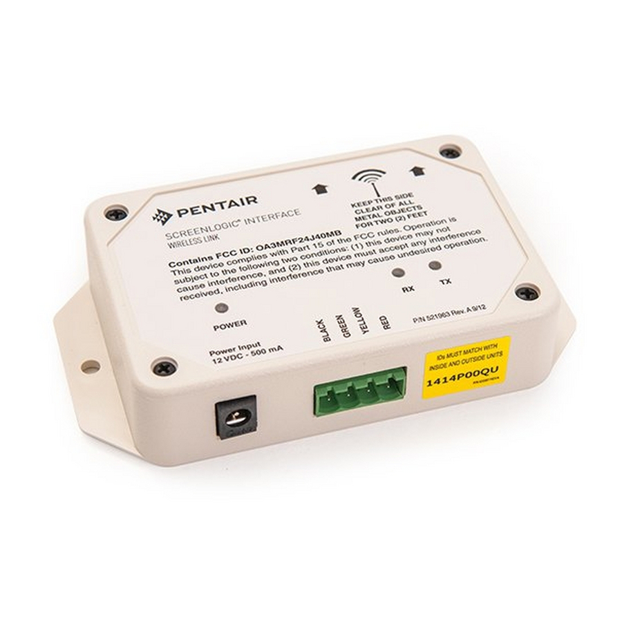
- Page 7 Case Transceiver Circuit board Back plate mounting point (4x) Transceiver Connector Transceiver case retaining screws RED (15 V - PIN 4) (x2) YEL (+ DT - PIN 3) GRN (- DT - PIN 2) BLK (GND - PIN 1) COM PORT screw terminal connector on IntelliTouch ®...
- Page 8 Connect the Transceiver connection cable to the COM Port on Control System Circuit Board WARNING Switch OFF the main system power to the Load Center before making any connections. Unlatch the enclosure door spring latche(s), and open the door. Remove the two retaining screws securing the high voltage cover- panel, and remove it from the enclosure.
- Page 9 Route the four conductor transceiver connection cable into the lower plastic grommet, up through the low voltage raceway to the circuit board. Control panel Circuit board Raceway Insert the four wires into the screw terminals of the COM PORT plug located on the circuit board as shown on page 6. Using a small flat-blade screwdriver, secure the wires with the screws.
- Page 10 10. Switch the power on to the IntelliTouch or EasyTouch Control ® ® System Load Center. 11. Proceed to the “Connect the ScreenLogic Interface Indoor Wireless Transceiver to the ScreenLogic Interface Protocol Adapter” on page 8. SCREENLOGIC INTERFACE Wireless Connection Kit Installation Guide ®...
- Page 11 Interface Indoor Wireless Transceiver to the ® ScreenLogic Interface Protocol Adapter To connect the ScreenLogic Interface indoor wireless transceiver to the ScreenLogic Interface Protocol adapter: Using the provided connection cable, connect one end of the cable to the ScreenLogic Interface Protocol adapter and the other end to the ScreenLogic Interface indoor wireless transceiver.
Need help?
Do you have a question about the SCREENLOGIC INTERFACE and is the answer not in the manual?
Questions and answers