Advertisement
Class AB Circuitry
Fully 2 Ohm Stable Stereo Operation
Military Spec. Audiophile Grade Components
High Efficiency MOSFET Power Supplies
-Multi-stranded power torroid
-IRFZ44 MOSFET Transistors
Efficient Bipolar Output Transistors
Oversized Capacitor Bank
Wire Free PC Board Layouts
Gold Plated Input and Output Connectors
Variable Highpass and Lowpass Electronic Crossovers
Simultaneous Mono/Stereo Operation Capability
Internally Bridgeable
5 Way Protection Circuitry
Soft Start, On/Off Circuitry
High Level Inputs
Two Year Limited Warranty
The quality of installation may affect the performance and reliability of your Crossfire product. If you have any doubts or questions regarding installation, you may
wish to contact your authorized Crossfire dealer. Remember to follow all wire and fuse requirements suggested in this manual. Warranty may void if proper
installation technique is not used (refer to warranty section in the rear of this manual).
Appropriate mounting is very important for prolonged life expectancy of any amplifier. Select a location of applicable space that allows sufficient airflow and
provides protection from moisture. Keep in mind that an amplifier should never be mounted upside down. Upside down mounting will compromise heat dissipation
through the heatsink and will engage the thermal protection circuit much sooner. Excessive heat can shorten your amplifier's life. To maximize heat dissipation, be
sure to leave at least 2.5 inches of clearance around the amplifier. Fans should be used in correspondence with an escape duct for heat when mounting the amplifier
in an enclosed or restricted area.
Avoid slipping and scratching your new Crossfire amplifier by pre-drilling the mounting holes with either a 1/8" or 3mm diameter drill bit when using the screws
supplied in the accessory kit. Always investigate the mounting area thoroughly for electrical wires, vacuum lines, and brake or fuel lines before you start to prevent any
potentially expensive mistakes.
Incorrect Mounting
x
Heat is trapped inside the amplifier, shortening
the life of the electronic components.
TEK AMPLIFIERS
TEK AMPLIFIERS
Features
Features
Please read all instructions before installation!
Please read all instructions before installation!
MODEL:
TEK35.2
RMS Power/4 ohms
35W x 2
Bridge Power, Max.
140w x 1
T.H.D.
0.02%
Bandwidth + 3dB
5Hz-38KHz 5Hz-38KHz 5Hz-38KHz 5Hz-38KHz 5Hz-38KHz 5Hz-38KHz 5Hz-38KHz 5Hz-38KHz
Signal To Noise
>93dB
Damping Factor
>150
Separation
60dB
Input Sensitivity
180mV-4V 180mV-4V 180mV-4V 180mV-4V 180mV-5V 180mV-4V 180mV-4V 265mV-5V
Input Impedance
20Kohm
Power Fuse
15 Amp
Dimensions W:
9.3 IN
H:
2.1 IN
L:
8.35 IN
CROSSOVER
Variable Low Pass
50-150Hz
Variable High Pass
50-150Hz
X-Over Slope
12dB
45hz BOOST
Yes
All specifications are with 12.5 volts DC. Typical output with 14.4 volts DC is 20% higher.
IMPORTANT
IMPORTANT
MOUNTING
MOUNTING
Correct Mounting
O
Heat is lifted from the amplifier heatsink.
Specifications
Specifications
TEK50.2
TEK75.2
TEK100.2 TEK150.2 TEK35.4
50W x 2
75W x 2
100W x 2
150W x 2
200W x 1
300W x 1
400W x 1
600W x 1
0.02%
0.02%
0.02%
0.02%
>95dB
>97dB
>97dB
>100dB
>200
>200
>200
>300
60dB
62dB
62dB
68dB
20Kohm
20Kohm
20Kohm
20Kohm
20 Amp
25 Amp
(2)25 Amp (2)30 Amp 25 Amp
9.3 IN
9.3 IN
9.3 IN
9.3 IN
2.1 IN
2.1 IN
2.1 IN
2.1 IN
10.32 IN
11.5 IN
13 IN
15 IN
50-150Hz 50-150Hz 50-150Hz
50-150Hz
50-150Hz 50-150Hz 50-150Hz
50-150Hz
12dB
12dB
12dB
12dB
Yes
Yes
Yes
Yes
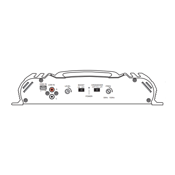
HIGH IN
LOW IN
R
L
R
L
TEK50.4
TEK400.1
35W x 4
50W x 4
200 x 1
150W x 2
200W x 2
400 x 1
0.02%
0.02%
0.02%
>95dB
>95dB
>94dB
>150
>150
>310
61dB
61dB
NA
20Kohm
20Kohm
20Kohm
(2)20 Amp (2)25 Amp
9.3 IN
9.3 IN
9.3 IN
2.1 IN
2.1 IN
2.1 IN
11.5 IN
11.5 IN
11.5 IN
50-150Hz 50-150Hz 50-150Hz
50-150Hz 50-150Hz 50-150Hz
12dB
12dB
12dB
No
No
No
BOOST
CROSSOVER
LEVEL
FREQ
ON OFF
HPF FULL LPF
POWER
50Hz 150Hz
TEK AMPS
Advertisement
Table of Contents

Subscribe to Our Youtube Channel
Related Manuals for Crossfire TEK Series


Summary of Contents for Crossfire TEK Series
- Page 1 Avoid slipping and scratching your new Crossfire amplifier by pre-drilling the mounting holes with either a 1/8" or 3mm diameter drill bit when using the screws supplied in the accessory kit. Always investigate the mounting area thoroughly for electrical wires, vacuum lines, and brake or fuel lines before you start to prevent any potentially expensive mistakes.
- Page 2 Power Connections All Crossfire amplifiers are designed to work within 10.5 to 16 volts DC. Therefore, as a precaution, the vehicle's electrical system should be checked for correct voltage supply with the help of a voltmeter. First, connect the test leads of the voltmeter to the battery terminals with the ignition of the vehicle in the off position.
-
Page 3: Remote Turn-On
To prevent damage, use the following formulas to help you figure out the load you are placing on your amplifier. If you have any difficulties, please contact your local Crossfire dealer or Crossfire's Technical assistance at 562-483-8111. - Page 4 TWO CHANNEL AMPIFIERS Two Channel Operation (stereo) Three Channel Operation (stereo/mono) MODELS MODELS FUSE FUSE TEK35.2 +12V TEK35.2 +12V BRIDGED BRIDGED TEK50.2 TEK50.2 TEK75.2 TEK75.2 POWER POWER SPEAKER SPEAKER TEK100.2 TEK100.2 TEK150.2 TEK150.2 FOUR CHANNEL AMPIFIERS Three Channel Operation (stereo & mono) Four Channel Operation (stereo) MODELS MODELS...
-
Page 5: Connecting The Wires
CONNECTING THE WIRES CONNECTING THE WIRES At this point, the power, ground, and remote wires should be run to the general location of where the amplifier is to be mounted. If the wires are to be hidden under the carpet, you now need to cut a slit for them to come through. To do this, place the amplifier in the location it is to be mounted to verify where the slits need to be. - Page 6 If your system is lacking low bass response, locate the boost switch next to the crossover. By placing this switch in the on position, 6dB of boost centering around 45Hz will be added. In the OFF position no boost is added to the output signal. This boost switch is available on all Crossfire TEK amplifiers with the exception of the...
-
Page 7: Operation
OPERATION The Crossfire TEK400.1 is a mono-block amplifier. Unlike other Crossfire TEK amplifiers, this amplifier operates as a single channel, therefore the amplifier cannot be bridged. Do not be fooled by the two sets of speaker outputs. Two outputs are provided strictly for convenience and are paralleled internally on the circuit board of the amplifier. - Page 8 speaker 1 Daisy chain amplifiers HIGH IN LOW IN LEVEL CROSSOVER CROSSOVER FREQ LINE OUT HPF FULL LPF HPF FULL LPF POWER 50Hz 150Hz speaker 2 Source output Crossover select - amp HIGH IN LOW IN LEVEL CROSSOVER CROSSOVER FREQ LINE OUT HPF FULL LPF HPF FULL LPF...
Need help?
Do you have a question about the TEK Series and is the answer not in the manual?
Questions and answers