Table of Contents
Advertisement
Quick Links
Advertisement
Table of Contents

Related Manuals for Palmer MicroCorr Digital


Summary of Contents for Palmer MicroCorr Digital
- Page 1 Users Guide Ty Coch House Llantarnam Park Way Cwmbran NP44 3AW United Kingdom Tel: +44 (0) 1633 489479 Fax: +44 (0) 1633 877857 Email: info@palmer.co.uk Internet: www.palmer.co.uk Mcorr Dig UG Issue 5b August 2003 Based on SW-042-01-109a Based on FW-042-02-107a...
-
Page 2: Table Of Contents
MicroCorr Digital Users Guide Introduction and Features......................3 New features..........................3 Operational Benefits ........................4 Principle of Correlation ......................5 System Overview........................6 Standard system configuration ....................6 Optional accessories ......................... 6 Fully Digital Correlation ......................7 Features of the correlator unit ....................8 Features of the Out Stations...................... -
Page 3: Introduction And Features
• Tricorrelation (optional third Out Station/sensor) automatically calculates site- specific velocity • Data replay function allows immediate post-processing or off-line correlation • Software upgrades downloaded directly from www.palmer.co.uk • Results transferable into Windows PC for post-processing or export Best in the field Leak detection staff require a high performance correlator in order to maximise their productivity (number of leaks found per hour) and minimise the incidence of “dry”... -
Page 4: Operational Benefits
• Improved reliability with less downtime • Lightweight and robust • Easily integrates into Company-specific reporting • New software versions available from www.palmer.co.uk • Ground microphone “foot” option to improve versatility • Permalog “Patroller link” option to improve versatility • Designed for easy portability Fully automatic •... -
Page 5: Principle Of Correlation
Principle of Correlation In the "classic" correlation process, two sensors are deployed on pipe fittings ("dry" connection) or connected to hydrants ("wet" connection). The sensors are positioned either side of the suspected leak position. Noise is created by the leak as it escapes from the pipe under pressure. -
Page 6: System Overview
System Overview Standard system configuration The standard MicroCorr Digital system comprises the following equipment:- 1. Control Unit 2. External Antenna for C.U. 3. Carry strap for C.U. 4. Red Out Station 5. Blue Out Station 6. 2 x External Antennae for O/S 7. -
Page 7: Fully Digital Correlation
Fully Digital Correlation Digital sensor • New sensor with improved sensitivity to low frequency noise (for plastic and large diameter pipes and low pressure situations) - down to 1.0Hz • Wider dynamic range than any previous sensor - can distinguish leak noises much quieter than previous sensors •... -
Page 8: Features Of The Correlator Unit
Features of the correlator unit Large backlit colour display Rubber hand grip with protective screen Tactile rubber keypad Carry-strap attachment Battery compartment (accessed from underside) Injection moulded housing Headphone / charger External antenna / magmount connector connection Sensor Communications connector connector... -
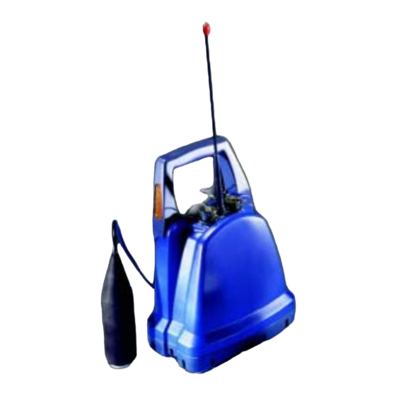
Page 9: Features Of The Out Stations
Features of the Out Stations The Out Station consists of a transmitter unit (red, blue – or optionally yellow) and a digital sensor unit complete with cable to connect to the transmitter. Its design incorporates sensor stowage and cable wrap. Detachable antenna Sensor... - Page 10 Rear of transmitter On/Off switch with integral flashing LED Sensor stowage Top view of transmitter – connector covers removed Headphones / charger connector Communications connector Sensor connector Antenna connector Top view of transmitter – connector covers fitted...
-
Page 11: Microcorr ® Digital Correlator Unit Operational Features
CANCEL Keypad functions pqrs wxyz MicroCorr Digital has an alpha-numeric keypad, similar to that of a mobile phone including a full stop, cancel, enter and up/down arrows. Navigation through the menus uses combinations of these keys. • UP/DOWN arrows will select items from within a list •... -
Page 12: Using The Microcorr Digital Correlator
Only batteries/battery-packs supplied by Palmer Environmental must be used. The Palmer sealed battery packs contain circuitry to prevent overcharging and overdischarging. Step 1: Charging and installing batteries The battery packs for the correlator and the Out Stations are supplied as separate items and will need to be fully charged although they are supplied quarter charged. - Page 13 Remember to turn control unit and Out Stations off after disconnecting charger cables. Although the batteries are rechargeable, they may eventually need to be replaced. Only batteries configured to the correct specification and type must be used. These are available from Palmer Environmental. TWO OUT STATIONS CONNECTED VIA CHARGER TO MAINS...
-
Page 14: Step 2: Set Up And Deployment Of Out Stations
Step 2: Set up and deployment of Out Stations Once the batteries have been charged and installed in the correlator and the Out Stations, connect the antennae, connect a sensor cable and sensor to each Out Station. Switch on each transmitter by pressing the On / Off button on the back. Transmitter switch functions To switch the transmitter on, press the switch on the rear of the transmitter once momentarily. -
Page 15: Step 3: Switching On The Correlator
Step 3: Switching on the Correlator Switch the correlator on by pressing the On/Off switch momentarily. A number of system tests are carried out on power up to ensure the correlator is fully functional. After a few seconds the main correlation screen will appear on the display as shown below. Note, this is the default screen on start-up to enable the operator to start correlating immediately. -
Page 16: Correlating
Correlating The screen shown on page 15 is the first screen that appears on the control unit when it is switched on. Once the ENTER key is pressed the system will begin to correlate. Correlation can be stopped by pressing the ENTER key again. This can be used for quick surveys without having to input any pipe data. -
Page 17: Main Menu
Main Menu Correlate See previous page for quick correlation instructions or Correlation Screen section for more in depth instructions. File Enables the user to load previously saved files or save a current correlation. The control unit can store approximately 30 files. - Page 18 Press 1(Save) The following screen is displayed. The current correlation information details can be typed and saved. Press 2(Load) The saved correlation will be displayed. Arrow over the required saved file and press 2. Loaded file name is displayed in green From a loaded file the control unit can undertake post correlation.
-
Page 19: Regression Analysis
Regression Analysis Regression Analysis provides an additional way of pinpointing leak positions by using a set of correlation results, rather than an individual correlation result. This also provides a way of measuring an accurate velocity. The time delay / distance relationship of the correlation is linear, as the distance between a sensor and the leak noise increases, the time taken for the sound to reach the sensor increases proportionally with the distance. - Page 20 Then press 1 to add the second correlation result. A second cross will appear and a line will pass through both. A result will be given on the leak position and velocity, but we recommend the user add a third result for a more confident result. Then press 1 to add the third correlation result.
- Page 21 Press 2 (Remove / Restore) Allows you to select a suspicious correlation for removal. After pressing 2, use the arrow keys to select the cross on the regression graph for removal (a box appears around the selected cross) then press ENTER. Press 3 (Load data) Retrieves previously stored regression analysis graph results.
-
Page 22: Set-Up
Set-up Press 1(Correlate on start-up) Toggles between YES and NO. If set to YES, the control unit will go straight to the correlate screen after turning on. If set to NO, the control unit will go straight to the Main Menu after turning on. Press 2(Default filters) Toggles between CLEAR and RETAIN. - Page 23 Press 6(Power Saving) Press 1 to toggle the System power off between NEVER and 5, 10, 15, 20, 25, 30, 35, 40, 45, 50, 55 and 60 minutes duration. Press 2 to toggle the Backlight off between NEVER and 5, 10, 15, 20, 25, 30, 35, 40, 45, 50, 55 and 60 minutes duration.
-
Page 24: Test And Service
Test and Service Press 1(Restore default pipe data) Wait a few seconds and the default pipe data will be restored to the control unit. Press 2(Units are Metric) Toggle between METRIC and IMPERIAL measurement units. Press 3(Time is in milliseconds) Toggles between MILLISECONDS and SECONDS Press 4(Using HP printer) Toggle between HP and EPSON printer. - Page 25 Press 6(Set clock) Set the clock according to the user preferred format. Press 7(Debug Messages are Off) Toggles between ON and OFF. This should normally be set to OFF and is normally only used during fault diagnosis. Press 8(Information) Connect sensors to Out Stations and turn on before pressing 8. This displays the current firmware and software version currently installed on the MC Digital.
-
Page 26: Other System Options
Press 9(Diagnostics) Displays a series of numbers. This is only used during fault diagnosis Other System Options The MC Digital is designed for versatility. Pressing 1 will activate the Permalog Patroller Link, changing the MC Digital into a Permalog Patroller. (This is only possible if the Patroller Link radio has been purchased, not fitted as standard) -
Page 27: Correlation Screen
Correlation Screen A dashed cursor line shows the position of the largest peak (best result). The dashed cursor line can be moved once the correlation has been stopped, by using the arrow keys. Moving the dashed cursor line alters the correlation distance. This screen shows the result of a correlation where the position of the leak is. -
Page 28: Pipe Data
Pipe data Press 2(Pipe data) To accurately locate a leak position the user must enter the correct information with respect to the physical properties of the pipe. Each section must be entered to be accepted by the system. Press 5 to Add new pipe data. A default setting appears. - Page 29 Press 1 to enter Length, the distance between the sensors. In this example 124m. Press 2 to enter material type, use the arrow keys to select the required pipe material and press ENTER. In this example cast iron is selected.
- Page 30 Press 3 to enter the diameter of the pipe. In this example 80mm. The velocity column will then automatically be updated. In this example 1.280 m/ms. To add another pipe length for mixed material situations, press 5 to add another pipe. If working on mixed materials, work from the sensor colour displayed at the bottom of the pipe data screen, back to the sensor colour at the top of the screen.
- Page 31 To delete a pipe, use the arrow keys to highlight the relevant pipe to remove and press 6. To delete all pipe data press 0. To use a manual velocity the user has calculated, press 4 and type in the new velocity value, this will automatically update the default value for the current correlation only.
-
Page 32: Zoom
Zoom Press 5 (Zoom) To see a more enhanced view of the leak centred around the dashed cursor line. Moving the dashed cursor line along the graph to the required point then press 5. Use the arrow keys to zoom in or out stage by stage. For a quicker zoom press 1 to zoom to maximum view or press 5 to zoom to a minimum view. -
Page 33: Peak Suppression Screen
Peak Suppression Screen Press 6(Peak Suppression) To suppress a section of the time delay range from the current correlation. This may be used to remove known leaks or demand usage that may be hiding unknown leaks. Move the dashed cursor line to the start point of the data to be removed and press 1 to select a start point. -
Page 34: View Settings
View Settings Press 7 (View Settings) During correlation or after stopping a correlation press 7 to view all pipe data and filter settings currently in use. A pop up box appears to display the information. Press Cancel to remove the display. -
Page 35: Calculate Velocity
Calculate Velocity Press 8(Calc Vel) After stopping correlating the option to calculate velocity appears. A velocity check gives a more accurate velocity of the pipe to be correlated instead of using the default velocity value. To calculate velocity a leak must be present, either real or induced. The leak can either be between the sensors called an “In Bracket”... - Page 36 A new velocity will be displayed under the correlation graph The control unit then gives you the option to either use the calculated velocity by pressing ENTER or CANCEL to ignore it. By accepting the calculated velocity value, the default velocity value under Pipe Data will be replaced with the new calculated velocity value.
-
Page 37: Filters
Filters If correlating with pipe data entered, the default filter settings will be used depending on the properties of the pipe. Some times this may not be accurate enough to filter out unwanted frequencies, so the user may wish to alter the filer settings to remove certain frequencies that are influencing the current correlation. - Page 38 Press 1 (Select cursor) This toggles between the two cursor lines. Only the longer dashed cursor line can be moved. Press 2 (Low cut-off) When the left cursor line has be selected the low cut off option is displayed. Move the left cursor to the required position and press 2. This will remove all frequencies to the left of the cursor line.
- Page 39 Press 3 (Notch) This options allows a “notch” of frequencys to be filtered out. Move the selected cursor to the left of the area of frequency to be removed and press 3. A small arrow appears under the graph. In this example 81Hz is selected. Move the same cursor to the right of the area to be removed and press 3 again.
-
Page 40: Program Upgrade (Software And Firmware)
The MicroCorr Digital correlator and Out Stations have been designed so that their programs can be upgraded as the latest developments take place. The MicroCorr Digital Software is defined as the user interface within the base station, and the Firmware describes the program that communicates between the correlator base station and the Out Stations. - Page 41 When using the upgrade program for the MCD the following points should be noted: All of the correlation (.ked) files stored on the MicroCorr Digital will be deleted during the upgrade operation. Therefore the user must save any required correlation files to a PC before upgrading the software.
- Page 42 5. Click on the ‘Browse Firmware’ button and locate the firmware update file. 6. Ensure that the update file is newer than that currently installed on the system. (The latest version should always be used unless told specifically by your Palmer representative that an older version should be used).
-
Page 43: Technical Specification
Data replay for post processing Velocity measurement (tricorrelation option) User definable pipe types and velocities Language Selectable via menu Operating software User upgradable from www.palmer.co.uk Printer output RS232 to parallel printer PC download Via PC software, Windows compatible Dimensions 220mm x 250 x 100mm Weight 1.8Kg... - Page 44 Out Station Radio communication Single frequency digital transceiver Radio frequency UHF (local regulations apply) Controls ON/OFF (all functions remotely controlled and monitored from Base station) with LED status light Connections Headphones External antenna (if required) Battery type Rechargeable Lithium ion batteries, field replaceable Battery life >18 hours...
-
Page 45: Warranty
Warranty All equipment is warranted by Palmer Environmental Ltd to be free from defects in materials and workmanship for a period of one year (unless otherwise stated) from the date of shipment to the original customer. This warranty is only valid if the equipment has been installed and used in the correct manner as described in this manual.
Need help?
Do you have a question about the MicroCorr Digital and is the answer not in the manual?
Questions and answers