Table of Contents
Advertisement
Advertisement
Table of Contents

Summary of Contents for SELTEX V350
- Page 1 V350 USER MANUAL SWING GATE OPENER ≦150kg ≦150kg ≦1.75m ≦1.75m...
-
Page 2: Table Of Contents
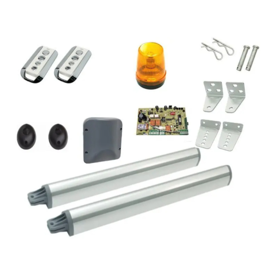
Content Important Safety Advice ......Content of the Kit ........Connection Diagram ......... Installation Guide ........Actuator ............04~07 ............. Control box AC cable wiring ..........Transformer ............. Connection PCBA ........... Actuator ............Warning light ..........Photocells ............Function of photocells ........ -
Page 3: Important Safety Advice
Important Safety Advice 1. Knowledge of relevant electro-technical regulations is required. 2. Training in use and maintenance of safety equipments is necessary. 3. Professional assistance is required when some mechanism adjustment is needed. 4. Always lay mains and control cables separately. 5. -
Page 4: Installation Guide
Installation Guide Actuator: The maximum opening angle depends on the distance (D) between the gate hinge to the edge of the pillar. The table below gives the opening angle according to (D) Angle (º) Distance D (mm) Pillar 0 < D < 170 0 <... - Page 5 Pillar side: Find the desired value B, according to the value D, as described in the previous table explaining the opening angle. Make sure the pillar side bracket is placed horizontally, with the use of a spirit level, before you drill the holes for the bracket. Mark a line on the lower frame of your gate, as shown below, and allow a 16mm vertical distance as it’s the height difference between the lowest part of the pillar side bracket, and the tallest part of the gate side bracket, as shown below.
- Page 6 Gate side: Make sure the gate side bracket is placed horizontally, with the use of a spirit level, before you drill the holes for the bracket. 16mm Use a spirit level to be sure that the mounting bracket can be placed horizontally.
- Page 7 Normally the nut is at a distance of 5mm from the fully close position. You can drive the nut to this position, in case the nut is not at the proper position. - Move the nut with a battery. The below diagrams indicate which direction the nut moves when the motor wires are connected directly to a 12VDC battery.
-
Page 8: Control Box
Control box: 1. Use a screw driver to unfasten the screws 2. Unfasten the two screws and remove the of the cover and open the control box. cover. AC12V Auto Clear LED1 +12V COM Warm GND NC LED O/C1 O/C2 GND ANT O / C Lamp 3. -
Page 9: Ac Cable Wiring
AC cable wiring: Connect the AC cable as shown below. 1. Mount the wire conduit at the left side of the control box. AC12V Auto Clear LED1 +12V COM Warm GND NC LED O/C1 O/C2 GND ANT O / C Lamp 2. -
Page 10: Transformer
Transformer: AC12V Auto Clear Put back the cover. LED1 +12V COM Warm GND NC LED O/C1 O/C2 GND ANT O / C Lamp Use a screw driver to fasten the 2 screws of the cover. AC12V Auto Clear LED1 +12V COM Warm GND NC LED O/C1 O/C2 GND ANT... -
Page 11: Connection Pcba
LED1 +12V COM Warm GND NC LED O/C1 O/C2 GND ANT PCBA: O / C Lamp AUTO To transformer To backup battery RF 2 (12V AC) (12V DC)(Option) Dip Switches Clear RF 1 Photocells connection See P.13 Motor Warning light connection connection See P.11... -
Page 12: Actuator
Actuator: Connect the four wires on the connector “ ” “ ”. Motor 1 Motor 2 Motor 1 Motor 2 Black Black Black Black Inward opening Outward opening For gates that open inwards, as shown below, For gates that open outwards, as shown connect the motor wires according to the below, connect the motor wires according to diagram above. -
Page 13: Warning Light
Warning light: 1. Open the warning light, 2. Remove the screws. in this direction. 3. Connect the warning light 4. Fix the warning light on the pillar. wires in the connector. (screws not provided). 5. The warning light wires come out from here. (wires not provided). -
Page 14: Photocells
Photocells (optional): See the picture on the right for installation. Fix the photocells on the pillar. Min. 30cm Connect the wires following the below diagram. (wires not provided) IPH6 IPH1 PHOTOCELL PHOTOCELL PHOTOCELL PHOTOCELL / OR / +12V +12V GNDCOM +12V GND NC ※... -
Page 15: Function Of Photocells
Function of photocells: Select a proper installation site, where the transmitter and receiver can align well. Connect to the opener’s PCBA as wiring diagram on page 13. Power on the system, try and see if it works properly by intercepting the IR between transmitter and receiver for times. The relay in the receiver should respond accordingly while LED switches ON and OFF. -
Page 16: Opening/Closing Learning
Opening / Closing learning: Please proceed with this function before using this product; otherwise the system will drive the gates improperly. E.g.: The gate can’t close completely or can’t open to the intended degree with some stroke length left unused. To activate this function, press “... -
Page 17: Remote Control
Remote Control: Each remote control has 4 keys. Choose two of them to proceed with RF learning for gate control and garden lamp control separately. Operation (open, close and stop) by remote control: The remote operation is very simple: one key press on the key will open the gate, the next press to stop, next to close the gate, the next to stop...and so on. -
Page 18: Setting Of The Dip Switches
Setting of the Dip Switches: 1 2 3 4 5 6 The default setting of dip switches: Key No. Function Auto-Close Auto-Close timer 60 Sec 30 Sec Gate Type Heavy Gate Light Gate 4 ~ 6 Current Limit Selected Unselected Do not change the setting of Gate Type unless you have problem finishing the auto-learning process. -
Page 19: Specifications
Specifications Actuator: Model V350 Input voltage 12V DC Power consumption 1.0 ~ 2.5A Macimum gate weight 150Kg Max. x 2 Macimum gate width 1.75M x 2 Speed 15.2mm/sec (no load) Duty cycle Overload protection Current detection Strock length 379mm Protection... -
Page 20: Declaration Of Ce Conformity
Declaration of CE Conformity The purchased gate opener kit “V350” is compliant with the following regulations, in terms of the essential conformity requirements of the R&TTE directives of 2014/53/EU and related directives, - EN301489-1 V1.9.2, 2011 - EN301489-3 V1.6.1, 2013 - EN300220-1 V2.4.1, 2012...