Table of Contents
Advertisement
Advertisement
Table of Contents

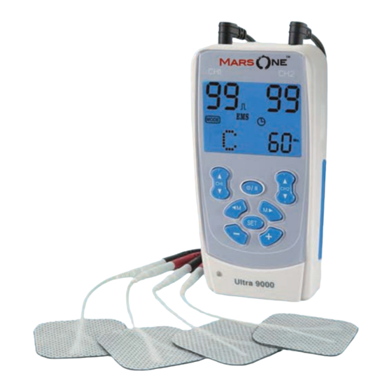
Summary of Contents for MarsOne Ultra 9000
-
Page 2: Table Of Contents
INDEX Chapter Contents Page Index General Description ..........2 Introduction ............2 Cautions..............8 Warnings ..............10 Contraindications ..........11 Precaution/Adverse Reactions… ......12 Construction… ............13 8. Technical Specifications ........15 Replaceable Parts ..........24 10. Accessories… ............24 11. Graphic Symbols………… ........26 12. -
Page 3: General Description
TENS does not work for everyone; however, in most patients The ULTRA 9000 Multi-function Combo Stimulator is a fully digital, it is effective in reducing or eliminating the pain, allowing for a return battery operated, pulse generator that sends electrical impulses to to normal activity. - Page 4 Pelvic Stimulation 3. Increasing local blood circulation 4. Muscle re-education Bladder Control for Women 5. Immediate post-surgical stimulation of calf muscles to Urinary incontinence is an inability to hold urine and/or faeces until prevent venous thrombosis able to reach a toilet. It is often temporary, and it always results from 6.
- Page 5 Types of Incontinence Facial Nerve Paralysis There are a number of different types, the Acute most common being stress incontinence, The condition is in the first 6 weeks of onset. A realistic prognosis urge incontinence and mixed incontinence. is not always possible at this stage as the degree of nerve dam- Stress Incontinence age has not yet been ascertained.
-
Page 6: Cautions
Following Nerve or Muscle Grafting cardiac arrhythmia. 6. Do not place electrodes on the front of the throat as spasm of the The use of stimulation will improve circulation and help with the pro- Laryngeal and Pharyngeal muscle may occur. Stimulation over duction of spontaneous movement patterns. -
Page 7: Warnings
may disrupt the healing process; 11. Do not place the electrodes over the carotid nerve, particularly in patients with a known sensitivity to the carotid sinus reflex. c. Over the menstruating or pregnant uterus; and 12. Electrical stimulation safety has not been established during d. -
Page 8: Construction
Chapter 6: PRECAUTIONS/ADVERSE REACTIONS Chapter 7 : CONSTRUCTION 1. Isolated cases of skin irritation may occur at the site of electrode placement during long-term application. 2. Effectiveness is dependent upon patient selection by a person qualified in the management of pain patients. 3. -
Page 9: Technical Specifications
Chapter 8 : TECHNICAL SPECIFICATIONS BACK SIDE (12) BELT CLIP (15) LOCK FACILITY The technical specification details of ULTRA 9000 Digital MULTI- (13) BATTERY CASE (16) SIDE STRIP FUNCTION COMBO STIMULATOR are as follows: MECHANISM TECHNICAL DESCRIPTION 01. Channel Dual, isolated between channels 02. - Page 10 Compliance Meter Sixty sets of treatment records can be 8. Normal Mode The pulse rate and pulse width are adjustable. stored. Total recorded time is 999 hours. It generates continuous stimulation based 12 Operating Temperature:0°~40°C on the setting value. Condition Relative Humidity: 30%~75% 9.
- Page 11 of ON Time should be no less than two P4 Synchronous times of the “Ramp” time in this mode. P5 Synchronous 14. Alternate The stimulation of the CH2 will occur after P6 Synchronous Mode(A) the 1st contraction of CH1 is completed. In P7 Synchronous this mode, the setting of ON Time should P8 Synchronous...
- Page 12 The transition from one frequency to the other is abrupt Sweep 1-30 Hz 8 Sec (square wave). Sweep 80-150 Hz 15 Sec 5. 10/10 ramped shift: The pulse frequency sweeps from –30% Sweep 1-150 Hz 8 Sec to +60% of the pulse frequency. Over a period of 10 seconds Output Quad polar (4 electrodes) the frequency changes from low to high and then changes...
- Page 13 1 second ramp down. It is repeated in a Palsy Programme 2 constant cyclic pattern. The details of the Output: Synchronous programme are given below. Pulse Width: Fixed Section Rate Width Contract Relax Ramp Cycle Pulse Rate: Fixed at 10Hz (Hz) (µs) (Sec.)
-
Page 14: Replaceable Parts
1 piece AC Power Adapter 1 piece The replaceable parts and accessories of ULTRA 9000 DIGITAL MULTI-FUNCTION COMBO STIMULATOR devices are as given The optional accessories for the device are available by order. below –Except leads, electrodes, battery and battery case cover, Please contact your distributor for buying the products if needed. -
Page 15: Graphic Symbols
Chapter 11 : GRAPHIC SYMBOLS sure that the plastic seal on the 9V battery is removed. Line up the positive and negative terminals on the battery with their corresponding terminals in the device. Make sure that the unit is Degree of Electrical Protection BF turned off. - Page 16 Treatments of the Pelvic Programs 4. Connect the cable of probe to the device as per the instructions. 5. Apply a thin coating of lubricating gel on the vagina opening or P1: Stress Incontinence apply a small amount of gel on the tip of the probe. P2: Stress Incontinence 6.
- Page 17 Facial Treatment Guidelines stimulation should be closely monitored by the therapist. Patients should not try this treatment without supervision as there are some indications that it may cause harm when used incorrectly. Facial Muscles Facial Electrical Stimulations If there is every possibility that the nerve will recover spontane- ously, albeit incompletely, then it may be better to let nature take its course.
- Page 18 ADDITIONAL SYMPTOMS WITH There are many physical symptoms associated with facial paralysis, but the effects will differ between individuals. They can vary in accordance with the degree of nerve damage, and the location of RAMSEY HUNT SYNDROME the damage. Hearing deficit Severe pain Long lasting pain GENERAL...
-
Page 19: Parameter Controls
Electrode Placement Chapter 13 : PARAMETER CONTROLS Electrode placement is crucial when treating facial palsy with PULSE DURATION stimulation. As most facial muscles are small it is important to treat Wider pulse duration settings will deliver stronger stimulation for any individual muscles, and use only the electrodes provided. - Page 20 TREATMENT MODE TIME DURATION Normal or Conventional TENS offers the practitioners complete con- The onset of pain relief should occur shortly after the intensity set- trol over all the various treatment parameters of the instrument. ting has been determined. However, in some cases, pain relief may take as long as 30 minutes to achieve, especially when using point Burst Mode is analogous to the Low Rate TENS technique except electrode placements and slow pulse rates.
-
Page 21: Lead Wire Maintenance
Chapter 17: ELECTRODE PLACEMENT Chapter 14 : ATTACHMENT OF ELECTRODE LEAD WIRES The placement of electrodes can be one of the most important parameters in achieving success with TENS or EMS therapy. It The wires provided with the system insert into the jack sockets is important that the physician experiments to determine optimum located on top of the device. -
Page 22: Electrodes
Chapter 19: APPLICATION OF RE-USABLE SELF Chapter 20 : ADJUSTING THE CONTROLS ADHESIVE ELECTRODES 1. Power On/Off/Pause Button Application The power of the lit unit can be turned on by pressing the On/Off/Pause button. You may start to adjust the settings when 1. - Page 23 The LED lamp will be lit up when the the modality is changed. Please re-adjust the intensity level by cord is connected. pressing the increment and decrement buttons when entering a new modality. The output amplitude will be ramped up to the setting value within two seconds when the mode or program under the same modality is changed.
- Page 24 b. Select a Mode *The setting of audio will not be stored after the unit is turned off. Always make the selection again in the above way if you want to Select a mode by pressing the “ ”or “ ”...
- Page 25 e. Set Timer After a mode is selected, always press “Set” to enter next The treatment time is adjustable between 1 – 60 minutes and setting, and press “Increment” or “Decrement” to adjust its value. The settings will be stored immediately after selected. Continue(C).
- Page 26 Press the “Lock” button to prevent accidental changes. f. Set Pulse Width Pulse Width is adjustable from 50 us to 12. Steps to set IF Programs 400 μs. Press “SET” control to enter this Remark: The IF can be used only when the AC power adapter is menu then press “Increment”...
-
Page 27: Battery Information
control to enter thismenu, then press Check & Delete Treatment Record Press “Lock” control and power simultaneously. The LCD will show “ ” or “ ” to adjust the setting. Unless otherwise instructed, set the the individual operation time. Press “ ”... - Page 28 3. Do not throw the used battery into fire. storing the batteries in your pocket or purse where the 4. Remove battery when the AC power cord is connected. terminals may accidentally come into contact with coins, keys or any metal objects. If you use rechargeable batteries, please follow the instructions.
-
Page 29: Safety-Technical Controls
The warranty applies to the stimulator only and covers both parts and labour relating thereto. Chapter 24 : MALFUNCTIONS Should any malfunctions occur while using the ULTRA 9000 Digital MULTI-FUNCTION COMBO STIMULATOR check whether the parameters are set to the appropriate form of therapy. -
Page 30: Electromagnetic Compatibility Information
Guidance and manufacturer’s declaration - electromagnetic emissions The ULTRA 9000 is intended for use in the electromagnetic environment specified below. The customer or the user of the ULTRA 9000 should assure that it is used in such an environment. Emissions test... - Page 31 RF transmitters, an electromagnetic site survey should be considered. If the measured field strength in the location in which the ULTRA 9000 is used exceeds the applicable RF compliance level above, the ULTRA 9000 should be observed to verify normal operation.
-
Page 32: Appendix: Test Environment
Recommended separation distances between portable and mobile RF communications equipment and the ULTRA 9000 The ULTRA 9000 is intended for use in an electromagnetic environment in which radiated RF disturbances are controlled. The customer or the user of the ULTRA 9000 can help prevent electromagnetic interference by maintain-...
Need help?
Do you have a question about the Ultra 9000 and is the answer not in the manual?
Questions and answers