Emerson Rosemount 644 Reference Manual
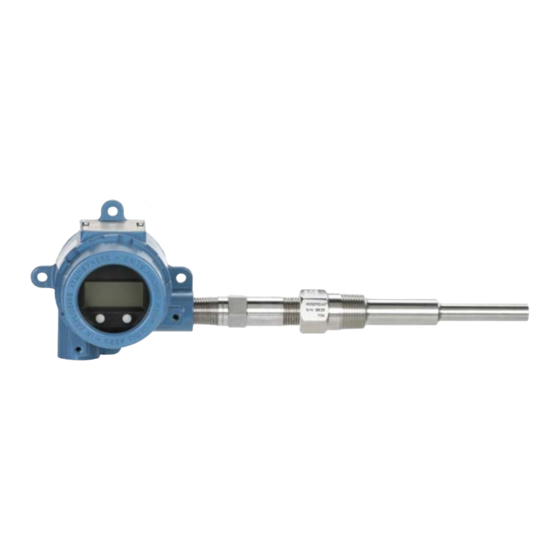
Temperature transmitter with hart protocol
Hide thumbs
Also See for Rosemount 644:
- Reference manual (134 pages) ,
- Quick start manual (48 pages) ,
- Service manual (37 pages)
Table of Contents
Advertisement
Quick Links
Download this manual
See also:
Service Manual
Advertisement
Table of Contents

Related Manuals for Emerson Rosemount 644


Summary of Contents for Emerson Rosemount 644
- Page 1 Reference Manual 00809-0200-4728, Rev RA April 2015 Rosemount 644 Temperature Transmitter ® with HART Protocol...
- Page 3 The products described in this document are NOT designed for nuclear-qualified applications. Using non-nuclear qualified products in applications that require nuclear-qualified hardware or products may cause inaccurate readings. For information on Rosemount nuclear-qualified products, contact a Emerson Process Management Sales Representative.
- Page 4 Reference Manual Title Page 00809-0200-4728, Rev RA April 2015...
-
Page 5: Table Of Contents
Reference Manual Table of Contents 00809-0200-4728, Rev RA April 2015 Contents 1Section 1: Introduction Safety messages ............1 1.1.1 Warnings . - Page 6 Table of Contents Reference Manual April 2015 00809-0200-4728, Rev RA 2.6.2 Configuring the sensor(s) .........17 2.6.3 Setting output units .
- Page 7 Reference Manual Table of Contents 00809-0200-4728, Rev RA April 2015 Installation procedures ..........49 3.4.1 Set the alarm switch .
- Page 8 Table of Contents Reference Manual April 2015 00809-0200-4728, Rev RA 6Section 6: Troubleshooting Overview .............79 Safety messages .
- Page 9 Reference Manual Table of Contents 00809-0200-4728, Rev RA April 2015 A.4.3 Considerations ..........119 Specifications and reference data for 644 HART Head Mount.
- Page 10 Table of Contents Reference Manual April 2015 00809-0200-4728, Rev RA Table of Contents...
-
Page 11: 1Section 1: Introduction
Section 1: Introduction Reference Manual April 2015 00809-0200-4728, Rev RA Section 1 Introduction Safety messages Instructions and procedures in this section may require special precautions to ensure the safety of the personnel performing the operations. Information that potentially raises safety issues is indicated by a warning symbol ( ). -
Page 12: Overview
Section 7: Safety Instrumented Systems (SIS) Certification provides identification, installation, configuration, operation and maintenance, and inspection information for Safety Instrumented Systems as it pertains to the Rosemount 644 Head Mount and Field Mount Temperature Transmitter. Appendix A: Specifications and Reference Data This section supplies transmitter specifications and reference data as well as transmitter ordering information. -
Page 13: Transmitter Overview
00809-0200-4728, Rev RA April 2015 1.2.2 Transmitter overview The Rosemount 644 Head Mount and Field Mount Temperature Transmitters support the following features: HART configuration with Selectable HART revision capability (Revisions 5 or 7) Accepts either 1 or 2 inputs from a wide variety of sensor types (2, 3, and 4-wire RTD, ... -
Page 14: Considerations
Reference Manual Section 1: Introduction 00809-0200-4728, Rev RA April 2015 Considerations 1.3.1 General Electrical temperature sensors such as RTDs and thermocouples produce low-level signals proportional to their sensed temperature. The 644 converts the low-level sensor signal to a standard 4–20 mA DC or digital HART signal that is relatively insensitive to lead length and electrical noise. -
Page 15: Return Of Materials
Return of materials To expedite the return process in North America, call the Emerson Process Management National Response Center toll-free at 800-654-7768. This center, available 24 hours a day, will assist you with any needed information or materials. -
Page 16: Transmitter Security
Transmitter security 1.5.1 Available security options There are three security methods to utilize with the Rosemount 644 Transmitter. Software Security Switch (Write Protect) HART Lock ... -
Page 17: Overview
Reference Manual Section 2: Configuration 00809-0200-4728, Rev RA April 2015 Section 2 Configuration Overview ..............page 7 Safety messages . -
Page 18: Warnings
Verify the latest Device Driver files are loaded on your systems to ensure proper communications. Download the latest Device Driver at www.emersonprocess.com or www.hartcomm.org Table 2-1. Rosemount 644 Device Revisions and Files Review Review Software date Identify device Find device driver files... -
Page 19: Surges/Transients
Set all transmitter hardware adjustments during commissioning to avoid exposing the transmitter electronics to the plant environment after installation. The Rosemount 644 can be configured either before or after installation. Configuring the transmitter on the bench using either a Field Communicator, AMS Device Manager, or LOI ensures all transmitter components are in working order prior to installation. -
Page 20: Choosing A Configuration Tool
Reference Manual Section 2: Configuration 00809-0200-4728, Rev RA April 2015 Figure 2-1. Powering the Transmitter for Bench Configuration 644 Head Mount and Field Mount 644 Rail Mount 250 Ω ≤ R ≤ 1100 Ω A. Power Supply B. Field Communicator Note Signal loop may be grounded at any point or left ungrounded. - Page 21 Reference Manual Section 2: Configuration 00809-0200-4728, Rev RA April 2015 Figure 2-2. Field Communicator Device Dashboard Interface Field Communicator menu trees and Fast Keys are available in Appendix C: Field Communicator Menu Trees and Fast Keys Configuring with AMS Device Manager With an AMS Device Manager software package, you can commission and configure instruments, monitor status and alerts, troubleshoot from the control room, perform advanced diagnostics, manage calibration, and automatically document activities with a single...
-
Page 22: Setting The Loop To Manual
Reference Manual Section 2: Configuration 00809-0200-4728, Rev RA April 2015 Figure 2-3. LOI Configuration Buttons A. Configuration Buttons Table 2-2. LOI Button Operation Button Left SCROLL Right ENTER LOI password An LOI password can be entered and enabled to prevent review and modification of device configuration via the LOI. -
Page 23: Hart Software Lock
Field Communicator are located in Appendix C: Field Communicator Menu Trees and Fast Keys. A Rosemount 644 Device Descriptor (DD) must be installed on the Field Communicator to verify configuration. Verify device configuration using Fast Key sequences in Table 2-3. -
Page 24: Verify And Review Configuration With Ams Device Manager
Reference Manual Section 2: Configuration 00809-0200-4728, Rev RA April 2015 Table 2-3. 644 Device Dashboard Fast Key Sequences Fast Key sequence Function HART 5 HART 7 Alarm Values 2, 2, 5, 6 2, 2, 5, 6 Damping Values 2, 2, 1, 5 2, 2, 1, 6 Lower Range Value (LRV) 2, 2, 5, 5, 3... - Page 25 Reference Manual Section 2: Configuration 00809-0200-4728, Rev RA April 2015 Checking or setting process variables The “Process Variables” menu displays process variables, including sensor temperature, percent of range, analog output, and terminal temperature. These process variables are continuously updated. The default primary variable is Sensor 1. The secondary variable is the transmitter terminal temperature by default.
-
Page 26: Basic Configuration Of The Transmitter
Reference Manual Section 2: Configuration 00809-0200-4728, Rev RA April 2015 Basic configuration of the transmitter The 644 must be configured for certain basic variables in order to be operational. In many cases, all of these variables are pre-configured at the factory. Configuration may be required if the transmitter is not configured or if the configuration variables need revision. -
Page 27: Configuring The Sensor(S)
Reference Manual Section 2: Configuration 00809-0200-4728, Rev RA April 2015 2.6.2 Configuring the sensor(s) Sensor configuration includes setting the information for: Sensor Type Connection Type Units Damping values Sensor Serial Number RTD 2-Wire Offset Configuring the sensor(s) with a Field Communicator The Configure Sensors method will guide you through the configuration of all necessary settings associated with configuring a sensor including:... -
Page 28: Setting Output Units
Reference Manual Section 2: Configuration 00809-0200-4728, Rev RA April 2015 Contact an Emerson Process Management representative for information on the temperature sensors, thermowells, and accessory mounting hardware that is available through Emerson Process Management. 2-wire RTD offset The 2-wire offset feature allows the measured lead wire resistance to be input and corrected for, which results in the transmitter adjusting its temperature measurement for the error caused by this added resistance. - Page 29 Reference Manual Section 2: Configuration 00809-0200-4728, Rev RA April 2015 Each of the base parameters and calculated outputs from those values can have a Unit of measure associated with it. Set the transmitter output to one of the following engineering units: Degrees Celsius ...
-
Page 30: Configure Dual Sensor Options
00809-0200-4728, Rev RA April 2015 Configure dual sensor options Dual-sensor configuration deals with the functions that can be used with a transmitter ordered with Dual Sensor inputs. In the Rosemount 644 these functions include: Differential Temperature Average Temperature ... -
Page 31: Average Temperature Configuration
Reference Manual Section 2: Configuration 00809-0200-4728, Rev RA April 2015 Figure 2-7. Configuring Differential Units with LOI DEG C UNITS VIEW CONFIG CHANGE ALL DEG F UNITS SENSOR CONFIG SENSOR 1 UNITS DEG R UNITS UNITS UNITS SENSOR 2 UNITS* KELVIN UNITS RERANGE DIFFRNTL UNITS*... - Page 32 Reference Manual Section 2: Configuration 00809-0200-4728, Rev RA April 2015 Average temperature configuration with LOI To configure average temperature on the LOI, the Units and Damping values must be set separately. Reference Figure 2-9 Figure 2-10 below for where to find these in the menu. Figure 2-9.
-
Page 33: Hot Backup Configuration
Reference Manual Section 2: Configuration 00809-0200-4728, Rev RA April 2015 2.7.3 Hot Backup configuration The Hot Backup feature configures the transmitter to automatically use Sensor 2 as the primary sensor if Sensor 1 fails. With Hot Backup enabled, the primary variable (PV) must either be First Good or Average. -
Page 34: Sensor Drift Alert Configuration
Reference Manual Section 2: Configuration 00809-0200-4728, Rev RA April 2015 Figure 2-11. Configuring Hot Backup with LOI HOT BACK MODE CALIBRAT HOT BACK PV VIEW CONFIG DAMPING HOT BACK RESET SENSOR CONFIG VARIABLE MAP BACK TO MENU UNITS EXIT MENU RERANGE ALM SAT VALUES LOOP TEST... -
Page 35: Configure Device Outputs
Reference Manual Section 2: Configuration 00809-0200-4728, Rev RA April 2015 Sensor drift alert configuration with AMS Device Manager Right click on the device and select Configure. On the Diagnostics Tab find the Sensor Drift Alert group box. Select to Enable the Mode and fill in the Units, Threshold and Damping values from the drop downs provided or select the Configure Sensor Drift Alert button and walk through the guided steps. -
Page 36: Damping
Reference Manual Section 2: Configuration 00809-0200-4728, Rev RA April 2015 The range of expected readings is defined by the Lower Range Value (LRV) and Upper Range Value (URV). The transmitter range values can be reset as often as necessary to reflect changing process conditions. - Page 37 Reference Manual Section 2: Configuration 00809-0200-4728, Rev RA April 2015 The value chosen for damping affects the response time of the transmitter. When set to zero (disabled), the damping function is off and the transmitter output reacts to changes in input as quickly as the intermittent sensor algorithm allows.
- Page 38 Reference Manual Section 2: Configuration 00809-0200-4728, Rev RA April 2015 Damping can be applied to a number of parameters in the 644 transmitter. Variables that can be damped are: Primary Variable (PV) Sensor 1 Sensor 2 Differential Temperature ...
-
Page 39: Configure Alarm And Saturation Levels
Reference Manual Section 2: Configuration 00809-0200-4728, Rev RA April 2015 2.8.3 Configure alarm and saturation levels In normal operation, the transmitter will drive the output in response to measurements between the lower to upper saturation points. If the temperature goes outside the sensor limits, or if the output would be beyond the saturation points, the output will be limited to the associated saturation point. - Page 40 Reference Manual Section 2: Configuration 00809-0200-4728, Rev RA April 2015 Configuring alarm and saturation levels with a Field Communicator From the HOME screen, enter the Fast Key sequence. 2, 2, 5, 6 Device Dashboard Fast Keys Configuring alarm and saturation levels with AMS Device Manager Right click on the device and select Configure.
-
Page 41: Configuring The Lcd Display
Reference Manual Section 2: Configuration 00809-0200-4728, Rev RA April 2015 2.8.4 Configuring the LCD display The LCD display configuration command allows customization of the LCD display to suit application requirements. The LCD display will alternate between the selected items with each item displaying for a 3 second interval. -
Page 42: Inputting Device Information
Reference Manual Section 2: Configuration 00809-0200-4728, Rev RA April 2015 Configuring LCD display with AMS Device Manager Right click on the device and select Configure. In the left navigation pane select Manual Setup. On the Display Tab there will be a group box with all available variables that can be displayed. - Page 43 Reference Manual Section 2: Configuration 00809-0200-4728, Rev RA April 2015 extended to 32 characters long. Neither parameter has any impact on the primary variable readings of the transmitter, it is only for information. The Date is a user-defined variable that provides a place to save the date of the last revision of configuration information.
-
Page 44: Configure Measurement Filtering
Reference Manual Section 2: Configuration 00809-0200-4728, Rev RA April 2015 2.10 Configure measurement filtering 2.10.1 50/60 Hz filter The 50/60 Hz Filter (also known as Line Voltage Filter or AC Power Filter) function sets the transmitter electronic filter to reject the frequency of the AC power supply in the plant. The 60 Hz or 50 Hz mode can be chosen. - Page 45 Reference Manual Section 2: Configuration 00809-0200-4728, Rev RA April 2015 feature can be switched ON or OFF and the threshold value can be changed to any value between 0 and 100% of the sensor limits with a Field Communicator. When the intermittent sensor detection feature is switched ON, the transmitter can eliminate the output pulse caused by intermittent open sensor conditions.
-
Page 46: Open Sensor Hold Off
Reference Manual Section 2: Configuration 00809-0200-4728, Rev RA April 2015 2.10.4 Open Sensor Hold Off The Open Sensor Hold Off option, at the normal setting, enables the 644 to be more robust under heavy EMI conditions. This is accomplished by the software having the transmitter perform additional verification of the open sensor status prior to activating the transmitter alarm. -
Page 47: Simulate Digital Signal (Digital Loop Test)
Reference Manual Section 2: Configuration 00809-0200-4728, Rev RA April 2015 Performing a loop test with AMS Device Manager Right click on the device and select Service Tools. In the left navigation pane select Simulate. On the Simulate Tab find the Perform Loop Test button in the Analog Output Verification group box. -
Page 48: Thermocouple Degradation Diagnostic
Reference Manual Section 2: Configuration 00809-0200-4728, Rev RA April 2015 Figure 2-20. Simulating the Digital Signal with LOI CALIBRAT VIEW CONFIG DAMPING SENSOR CONFIG VARIABLE MAP UNITS SIMULATE SNSR 1 RERANGE SIMULATE SNSR 2* ALM SAT VALUES LOOP TEST END SIMUL PASSWORD DISPLAY BACK TO MENU... -
Page 49: Minimum/Maximum Tracking Diagnostic
Minimum/maximum tracking diagnostic Minimum and maximum temperature tracking (min/max tracking) when enabled records minimum and maximum temperatures with date and time stamps on Rosemount 644 HART Head mount and Field mount Temperature Transmitters. This feature records values for Sensor Configuration... -
Page 50: Establishing Multi Drop Communication
Reference Manual Section 2: Configuration 00809-0200-4728, Rev RA April 2015 1, Sensor 2, Differential, Average, First Good and Terminal temperatures. Min/Max Tracking only records temperature maxima and minima obtained since the last reset, and is not a logging function. To track maximum and minimum temperatures, Min/Max Tracking must be enabled using a Field Communicator, AMS Device Manager, Local Operator Interface, or other communicator. -
Page 51: Changing A Transmitter Address
Reference Manual Section 2: Configuration 00809-0200-4728, Rev RA April 2015 Many Rosemount transmitters can be multi dropped. With the HART communications protocol, up to 15 transmitters can be connected on a single twisted pair of wires or over leased phone lines. -
Page 52: Using The Transmitter With The Hart Tri-Loop
Reference Manual Section 2: Configuration 00809-0200-4728, Rev RA April 2015 Changing transmitter address with a Field Communicator From the HOME screen, enter the Fast Key sequence. 1, 2, 1 Device Dashboard Fast Keys Changing transmitter address with AMS Device Manager Right click on the device and select Configuration Properties from the menu. -
Page 53: Set The Transmitter To Burst Mode
Reference Manual Section 2: Configuration 00809-0200-4728, Rev RA April 2015 2.13.1 Set the transmitter to burst mode To set the transmitter to burst mode, follow the steps below with the Fast Key sequence. Setting the burst mode with a Field Communicator From the HOME screen, enter the Fast Key sequence. - Page 54 Reference Manual Section 2: Configuration 00809-0200-4728, Rev RA April 2015 Using the Tri-Loop to detect sensor drift alert The dual-sensor 644 transmitter sets a failure flag (through HART) whenever a sensor failure occurs. If an analog warning is required, the HART Tri-Loop can be configured to produce an analog signal that can be interpreted by the control system as a sensor failure.
-
Page 55: Overview
Overview The information in this section covers installation considerations for the Rosemount 644 Temperature Transmitter with HART protocol. A Quick Start Guide (document number 00825-0200-4728) is shipped with every transmitter to describe recommended mounting and wiring procedures for initial installation. -
Page 56: Warnings
Reference Manual Section 3: Hardware installation 00809-0200-4728, Rev RA April 2015 3.2.1 Warnings Failure to follow these installation guidelines could result in death or serious injury. Make sure only qualified personnel perform the installation. Explosions could result in death or serious injury. Do not remove the connection head cover in explosive atmospheres when the ... -
Page 57: Installation Procedures
Reference Manual Section 3: Hardware installation 00809-0200-4728, Rev RA April 2015 Installation procedures Figure 3-1. Installation Flowchart Bench START Calibration? HERE FIELD INSTALL Set Failure Mode Switch BASIC SETUP Set Sensor Type Mount Transmitter Set Number of Wires Wire Transmitter Set Units Power Transmitter Set Range Values... -
Page 58: Set The Alarm Switch
Reference Manual Section 3: Hardware installation 00809-0200-4728, Rev RA April 2015 3.4.1 Set the alarm switch Make certain that the alarm switch is set to the desired position before putting the device into operation to ensure correct function in the instance of a failure. Without an LCD display Set the loop to manual (if applicable) and disconnect the power. -
Page 59: Mount The Transmitter
Reference Manual Section 3: Hardware installation 00809-0200-4728, Rev RA April 2015 3.4.2 Mount the transmitter Mount the transmitter at a high point in the conduit run to prevent moisture from draining into the transmitter housing. The 644 head mount installs In a connection head or universal head mounted directly on a sensor assembly. -
Page 60: Install The Device
Reference Manual Section 3: Hardware installation 00809-0200-4728, Rev RA April 2015 3.4.3 Install the device Head mount transmitter with DIN plate style sensor installation Attach the thermowell to the pipe or process container wall. Install and tighten the thermowell before applying process pressure. Verify the transmitter failure mode switch position. - Page 61 Verify the transmitter failure mode switch is in the desired position. To verify the correct installation of Integral Transient Protection (option code T1) on the Rosemount 644 device, confirm the following steps have been completed: Ensure the transient protector unit is firmly connected to the transmitter puck assembly.
- Page 62 Reference Manual Section 3: Hardware installation 00809-0200-4728, Rev RA April 2015 Field mount transmitter with threaded sensor installation Attach the thermowell to the pipe or process container wall. Install and tighten thermowells before applying process pressure. Attach necessary extension nipples and adapters to the thermowell. Seal the nipple and adapter threads with silicone tape.
- Page 63 Reference Manual Section 3: Hardware installation 00809-0200-4728, Rev RA April 2015 Rail mount transmitter and sensor Attach the transmitter to a suitable rail or panel. Attach the thermowell to the pipe or process container wall. Install and tighten the thermowell, according to plant standards, before applying pressure. Attach the sensor to the connection head and mount the entire assembly to the thermowell.
-
Page 64: Multichannel Installations
Reference Manual Section 3: Hardware installation 00809-0200-4728, Rev RA April 2015 Rail mount transmitter with threaded sensor Attach the transmitter to a suitable rail or panel. Attach the thermowell to the pipe or process container wall. Install and tighten the thermowell before applying pressure. -
Page 65: Lcd Display Installation
Reference Manual Section 3: Hardware installation 00809-0200-4728, Rev RA April 2015 Figure 3-5. Multichannel Installations Backup Battery Transmitter No. 1 Readout or Power Controller No. 1 Supply Transmitter No. 2 Readout or Controller No. 2 Between 250 Ω and 1100 Ω if no load resistor. 3.4.5 LCD display installation The LCD display provides local indication of the transmitter output and abbreviated diagnostic... - Page 66 Reference Manual Section 3: Hardware installation 00809-0200-4728, Rev RA April 2015 Use the following procedure to install the meter. If the transmitter is installed in a loop, secure the loop and disconnect the power. If the transmitter is installed in an enclosure, remove the cover from the enclosure. Decide meter orientation (the meter can be rotated in 90°...
-
Page 67: Overview
Wiring and powering the transmitter ......... . page 58 Overview The information in this section covers installation considerations for the Rosemount 644. A Quick Start Guide is shipped with every transmitter to describe mounting, wiring, and basic hardware installation procedures for initial installation. -
Page 68: Wiring And Powering The Transmitter
Reference Manual Section 4: Operation and Maintenance 00809-0200-4728, Rev RA April 2015 Wiring and powering the transmitter All power to the transmitter is supplied over the signal wiring. Use ordinary copper wire of sufficient size to ensure the voltage across the transmitter power terminals does not drop below 12.0 Vdc. -
Page 69: Sensor Connections
Reference Manual Section 4: Electrical Installation 00809-0200-4728, Rev RA April 2015 4.3.1 Sensor connections The 644 is compatible with a number of RTD and thermocouple sensor types. Figure 4-2 shows the correct input connections to the sensor terminals on the transmitter. To ensure a proper sensor connection, anchor the sensor lead wires into the appropriate captive terminals and tighten the screws. -
Page 70: Power The Transmitter
Reference Manual Section 4: Operation and Maintenance 00809-0200-4728, Rev RA April 2015 Thermocouple or millivolt inputs The thermocouple can be connected directly to the transmitter. Use appropriate thermocouple extension wire if mounting the transmitter remotely from the sensor. Make millivolt inputs connections with copper wire. -
Page 71: Ground The Transmitter
Reference Manual Section 4: Electrical Installation 00809-0200-4728, Rev RA April 2015 Figure 4-3. Powering the Transmitter for Bench Configuration 644 Head Mount and Field Mount 644 Rail Mount ≤ R ≤ 1100 A. Power supply B. Field Communicator Note Signal loop may be grounded at any point or left ungrounded. ... - Page 72 If the technique does not eliminate the transmitter alarms, try another technique. If all of the techniques do not eliminate or prevent the transmitter alarms because of high EMI, contact an Emerson Process Management representa- tive.
- Page 73 Reference Manual Section 4: Electrical Installation 00809-0200-4728, Rev RA April 2015 Option 2 Connect signal wiring shield to the sensor wiring shield. Ensure the two shields are tied together and electrically isolated from the transmitter housing. Ground shield at the power supply end only. Ensure the sensor shield is electrically isolated from the surrounding grounded fixtures.
- Page 74 Reference Manual Section 4: Operation and Maintenance 00809-0200-4728, Rev RA April 2015 Ground signal wiring shield at the power supply end. A. Sensor wires B. Transmitter C. Shield ground point Grounded thermocouple inputs Option 1 Ground sensor wiring shield at the sensor. Ensure the sensor wiring and signal wiring shields are electrically isolated from the transmitter housing.
- Page 75 Reference Manual Section 4: Electrical Installation 00809-0200-4728, Rev RA April 2015 ™ 4.3.4 Wiring with a Rosemount 333 HART Tri-Loop (HART/4–20 mA only) Use the dual-sensor option 644 transmitter that is operating with two sensors in conjunction with a 333 HART Tri-Loop HART-to-Analog Signal Converter to acquire an independent 4–20 mA analog output signal for each sensor input.
- Page 76 Reference Manual Section 4: Operation and Maintenance 00809-0200-4728, Rev RA April 2015 Figure 4-4. Load Limits Maximum Load = 40.8 X (Supply Voltage - 12.0) 4–20 mA dc 1240 1100 1000 Operating Region 40 42.4 12.0 Supply Voltage (Vdc) Electrical Installation...
-
Page 77: Overview
Switching HART Revision ........... . . page 76 Overview This section contains information on calibrating Rosemount 644 Temperature Transmitter. Field Communicator, AMS Device Manager, and Local Operator Interface (LOI) instructions are given to perform all functions. -
Page 78: Warnings
Reference Manual Section 5: Operation and Maintenance 00809-0200-4728, Rev RA April 2015 5.2.1 Warnings Failure to follow these installation guidelines could result in death or serious injury. Make sure only qualified personnel perform the installation. Explosions could resultin death or serious injury. Do not remove the connection head cover in explosive atmospheres when the ... -
Page 79: Trimming
Reference Manual Section 5: Operation and Maintenance 00809-0200-4728, Rev RA April 2015 5.3.1 Trimming The trim functions should not be confused with the rerange functions. Although the rerange command matches a sensor input to a 4–20 mA output—as in conventional calibration—it does not affect the transmitter’s interpretation of the input. - Page 80 Reference Manual Section 5: Operation and Maintenance 00809-0200-4728, Rev RA April 2015 Use the following procedures to perform a sensor trim on the 644: Performing a sensor trim using a Field Communicator Connect the calibration device or sensor to the transmitter. (If using an active calibrator, see “Active calibrator and EMF compensation”...
-
Page 81: Recall Factory Trim-Sensor Trim
Reference Manual Section 5: Operation and Maintenance 00809-0200-4728, Rev RA April 2015 5.4.1 Recall factory trim—sensor trim The Recall Factory Trim—Sensor Trim feature allows the restoration of the as-shipped factory settings of the analog output trim. This command can be useful for recovering from an inadvertent trim, incorrect Plant Standard or faulty meter. -
Page 82: Trim The Analog Output
Reference Manual Section 5: Operation and Maintenance 00809-0200-4728, Rev RA April 2015 EMF compensation allows the transmitter to provide sensor measurements that are unaffected by unwanted voltages, typically due to thermal EMFs in the equipment connected to the transmitter, or by some types of calibration equipment. If this equipment also requires steady sensor current, the transmitter must be set to “Active Calibrator Mode.”... -
Page 83: Performing A Scaled Output Trim
Reference Manual Section 5: Operation and Maintenance 00809-0200-4728, Rev RA April 2015 From the HOME screen, enter the Fast Key sequence. 3, 4, 5, 1 Device Dashboard Fast Keys Performing an analog output trim using AMS Device Manager Right click on the device and select Service Tools. In the left navigation pane select Maintenance. -
Page 84: Transmitter-Sensor Matching
Use Transmitter-Sensor Matching to enhance the temperature measurement accuracy of the system and if you have a sensor with Callendar-Van Dusen constants. When ordered from Emerson Process Management, sensors with Callendar-Van Dusen constants are NIST-traceable. The 644 accepts Callendar-Van Dusen constants from a calibrated RTD schedule and generates a special custom curve to match that specific sensor Resistance vs. - Page 85 Reference Manual Section 5: Operation and Maintenance 00809-0200-4728, Rev RA April 2015 Table 5-2. Standard RTD vs. RTD with Matched CVD Constants with Enhanced Transmitter Accuracy Option P8 System Accuracy Comparison at 150 °C Using a PT 100 (α=0.00385) RTD with a Span of 0 to 200 °C Standard RTD Matched RTD ±0.10 °C...
-
Page 86: Switching Hart Revision
Reference Manual Section 5: Operation and Maintenance 00809-0200-4728, Rev RA April 2015 Switching HART Revision Some systems are not capable of communicating with HART Revision 7 devices. The following procedures list how to change HART revisions between HART Revision 7 and HART Revision 5. 5.7.1 Switching HART Revision using the generic menu If the HART configuration tool is not capable of communicating with a HART Revision 7 device, it... -
Page 87: Overview
Reference Manual Section 6: Troubleshooting 00809-0200-4728, Rev RA April 2015 Section 6 Troubleshooting Overview ..............page 77 Safety messages . -
Page 88: Troubleshooting The 4-20 Ma/Hart Output
Reference Manual Section 6: Troubleshooting 00809-0200-4728, Rev RA April 2015 Troubleshooting the 4-20 mA/HART output Table 6-1. Rosemount 644 Troubleshooting Table for 4-20 mA Output Symptom or Potential Corrective action issue source Check the revision level of the transmitter device descriptors (DDs) stored in ... - Page 89 Reference Manual Section 6: Troubleshooting 00809-0200-4728, Rev RA April 2015 Table 6-1. Rosemount 644 Troubleshooting Table for 4-20 mA Output Symptom or Potential Corrective action issue source Connect a Field Communicator and enter the transmitter test mode to isolate ...
-
Page 90: Diagnostic Messages
2. If condition persists, replace the DEVICE DEVICE Electronics have failed. For example, transmitter. Contact the nearest Failure the transmitter may have Emerson Process Management Field ALARM ALARM experienced an electronics Service Center if necessary. FAIL FAIL failure while attempting to store information. -
Page 91: Diagnostic Messages: Warning
Reference Manual Section 6: Troubleshooting 00809-0200-4728, Rev RA April 2015 Table 6-2. Status: Failed – Fix Now Alert name LCD screen LOI screen Problem Recommended action 1. Verify sensor type and number of wires matched the Sensor Configuration of the device. -
Page 92: Other Lcd Display Messages
Reference Manual Section 6: Troubleshooting 00809-0200-4728, Rev RA April 2015 Alert name LCD screen LOI screen Problem Recommended action 1. Re-trim the device, make sure the user The value entered for the Calibration Error entered calibration points are close to [none] [none] user trim point was not... -
Page 93: Sis Certification
Section 7: Safety Instrumented Systems (SIS) Certification Reference Manual April 2015 00809-0200-4728, Rev RA Section 7 Safety Instrumented Systems (SIS) Certification SIS certification ............. page 83 644 safety certified identification . -
Page 94: Installation In Sis Application
Reference Manual Section 7: Safety Instrumented Systems (SIS) Certification 00809-0200-4728, Rev RA April 2015 Namur Software Revision Number 1.1.x (1) Namur Software Revision: Located on the adhesive device tag. You can also identify a certified 644 by its Device Revision which can be found using any HART compliant communicator. -
Page 95: Configuration
Reference Manual Section 7: Safety Instrumented Systems (SIS) Certification 00809-0200-4728, Rev RA April 2015 Configuration Use any HART capable configuration tool or the optional Local Operator Interface (LOI) to communicate with and verify the initial configuration or any configuration changes made to the 644 prior to operating in Safety Mode. -
Page 96: Sis Operation And Maintenance
Loop Test, Review – Device Variables, and view Status. The required proof test intervals depends upon the transmitter configuration and the temperature sensor(s) in use along with other factors. Refer to the Rosemount 644 FMEDA report for further information. 7.7.2... -
Page 97: Comprehensive Proof Test 3
Reference Manual Section 7: Safety Instrumented Systems (SIS) Certification 00809-0200-4728, Rev RA April 2015 Using Loop Test, enter the milliampere value representing a low alarm state. This tests for possible dormant current related failures. Check the reference meter to verify the mA output corresponds to the entered value. Use a Field Communicator to view detailed device status to ensure no alarms or warnings are present in the transmitter. -
Page 98: Specifications
Specifications The 644 must be operated in accordance to the functional and performance specifications provided in the Rosemount 644 Product Data Sheet (document number 00813-0100-4728). 7.8.1 Failure rate data The FMEDA report includes failure rates and common cause Beta factor estimates. -
Page 99: Sis Safety Transmitter Failure Values
Reference Manual Section 7: Safety Instrumented Systems (SIS) Certification 00809-0200-4728, Rev RA April 2015 7.8.2 SIS safety transmitter failure values IEC 61508 Safety Certified SIL 2 Claim Limit Safety accuracy: Span > = 100 °C ± 2% of process variable span Span <... - Page 100 Reference Manual Section 7: Safety Instrumented Systems (SIS) Certification 00809-0200-4728, Rev RA April 2015 Safety Instrumented Systems (SIS) Certification...
-
Page 101: Specifications
Reference Manual Appendix A: Specifications and Reference Data 00809-0200-4728, Rev RA April 2015 Appendix A Specifications and Reference Data Specifications ............. . page 91 4–20 mA / HART specifications . -
Page 102: Physical
Reference Manual Appendix A: Specifications and Reference Data 00809-0200-4728, Rev RA April 2015 Humidity limits 0–95% relative humidity Update time ≤ 0.5 seconds per sensor Accuracy (default configuration) PT 100 HART (0-100 °C): ±0.18 °C ±0.1 °C (when ordered with option P8) A.1.2 Physical Electrical connections... - Page 103 Reference Manual Appendix A: Specifications and Reference Data 00809-0200-4728, Rev RA April 2015 Mounting The 644R attaches directly to a wall or a DIN rail. The 644H installs in a connection head or universal head mounted directly on a sensor assembly, apart from a sensor assembly using a universal head, or to a DIN rail using an optional mounting clip.
-
Page 104: Performance
Appendix A: Specifications and Reference Data 00809-0200-4728, Rev RA April 2015 A.1.3 Performance EMC (electromagnetic compatibility) NAMUR NE 21 Standard The Rosemount 644 meets the requirements for the NAMUR NE 21 rating. Susceptibility Parameter Influence HART 6 kV contact discharge ... - Page 105 Reference Manual Appendix A: Specifications and Reference Data 00809-0200-4728, Rev RA April 2015 Sensor connections Figure A-1. 644 HART Head Mount Figure A-2. 644 HART Field Mount Specifications and Reference Data...
-
Page 106: 4-20 Ma / Hart Specifications
Reference Manual Appendix A: Specifications and Reference Data 00809-0200-4728, Rev RA April 2015 Figure A-3. 644 Sensor Connection Diagram: 644 Fieldbus and PROFIBUS PA Head Mount and 644 Rail Mount 1 2 3 4 1 2 3 4 1 2 3 4 1 2 3 4 4-wire RTD 2-wire... - Page 107 Reference Manual Appendix A: Specifications and Reference Data 00809-0200-4728, Rev RA April 2015 Power supply An external power supply is required for HART devices. The transmitter operates on 12.0 to 42.4 Vdc transmitter terminal voltage with load resistance between 250 and 660 ohms. A minimum of 17.75 Vdc power supply is required with a load of 250 ohms.
- Page 108 5*50nS Loop resistance added by protector: 22 ohms max. Nominal clamping voltages: 90 V (common mode), 77 V (normal mode) Accuracy Table A-2. Rosemount 644 Input Options and Accuracy Recommended Sensor options Sensor reference Input ranges Digital accuracy D/A accuracy min.
- Page 109 Reference Manual Appendix A: Specifications and Reference Data 00809-0200-4728, Rev RA April 2015 Table A-2. Rosemount 644 Input Options and Accuracy Recommended Sensor options Sensor reference Input ranges Digital accuracy D/A accuracy min. span Cu 50 (α = 0.00428) GOST 6651-94 –185 to 200...
- Page 110 Reference Manual Appendix A: Specifications and Reference Data 00809-0200-4728, Rev RA April 2015 Accuracy example When using a Pt 100 (α = 0.00385) sensor input with a 0 to 100 °C span: Digital accuracy = ±0.15 °C D/A accuracy = ±0.03% of 100 °C or ±0.03 °C ...
- Page 111 Reference Manual Appendix A: Specifications and Reference Data 00809-0200-4728, Rev RA April 2015 Table A-3. Ambient Temperature Effect Temperature effects per 1.0 °C Input range Sensor options Sensor reference Range (1.8 °F) change in ambient D/A effect (°C) temperature T ≥ 0 °C 0.007 °C 0.001% of span GOST R...
- Page 112 Reference Manual Appendix A: Specifications and Reference Data 00809-0200-4728, Rev RA April 2015 Table A-4. Transmitter Accuracy when ordered with Option Code P8 Minimum Digital Sensor reference Input ranges Sensor options (3)(4) span accuracy accuracy 2-, 3-, 4-wire RTDs °C °F °C °F...
-
Page 113: Dimensional Drawings
Reference Manual Appendix A: Specifications and Reference Data 00809-0200-4728, Rev RA April 2015 Dimensional drawings 644H (DIN A Head Mount) fieldbus and PROFIBUS device shown with OUNDATION HART device shown with captivated screw terminals standard compression screw terminals 60 (2.4) 60 (2.4) 33 (1.3) (1.3) - Page 114 Reference Manual Appendix A: Specifications and Reference Data 00809-0200-4728, Rev RA April 2015 644 Field Mount Transmitter exploded view Display compartment Terminal compartment with optional transient protector A. Nameplate F. Failure mode switch B. Cover G. Display connection C. Housing with electronics module H.
- Page 115 Reference Manual Appendix A: Specifications and Reference Data 00809-0200-4728, Rev RA April 2015 Mounting Kits for 644 Head Mount 644H Rail Clips 644R Rail & Walls Clips G-Rail (asymmetric) Top Hat Rail (symmetric) (part number 03044-4103-0001) A. Top hat rail grooves D.
- Page 116 (3.93) Mounting, 2-inch Pipe Note: A “U” Bolt is shipped with each universal head unless assembly option XA is ordered. Threaded Sensor Universal Head, 3-conduit Rosemount 644 with Transient Protector (Option code J1 or J2) (Option code T1) 108.0 59.2 (4.25)
- Page 117 Reference Manual Appendix A: Specifications and Reference Data 00809-0200-4728, Rev RA April 2015 Stainless Steel Housing for Biotechnology, Pharmaceutical Industries, and Sanitary Applications Sanitary Housing (Option Code S1, S2, S3, S4) Standard cover 76.2 (3.0) 33 (1.3) 79.8 (3.14) 27.9 (1.1) 25.4 (1.0) 24.4 44.5 (1.75)
-
Page 118: Ordering Information
00809-0200-4728, Rev RA April 2015 Ordering information The Rosemount 644 is a versatile temperature transmitter that delivers field reliability and advanced accuracy and stability to meet demanding process needs. Transmitter features include: HART/4-20 mA with Selectable Revisions 5 and 7 (Option Code A), ... - Page 119 00809-0200-4728, Rev RA April 2015 Table A-5. Rosemount 644 Smart Temperature Transmitter Ordering Information ★ The Standard offering represents the most common models and options. These options should be selected for best delivery. The Expanded offering is manufactured after receipt of order and is subject to additional delivery lead time.
- Page 120 00809-0200-4728, Rev RA April 2015 Table A-5. Rosemount 644 Smart Temperature Transmitter Ordering Information ★ The Standard offering represents the most common models and options. These options should be selected for best delivery. The Expanded offering is manufactured after receipt of order and is subject to additional delivery lead time.
- Page 121 00809-0200-4728, Rev RA April 2015 Table A-5. Rosemount 644 Smart Temperature Transmitter Ordering Information ★ The Standard offering represents the most common models and options. These options should be selected for best delivery. The Expanded offering is manufactured after receipt of order and is subject to additional delivery lead time.
- Page 122 00809-0200-4728, Rev RA April 2015 Table A-5. Rosemount 644 Smart Temperature Transmitter Ordering Information ★ The Standard offering represents the most common models and options. These options should be selected for best delivery. The Expanded offering is manufactured after receipt of order and is subject to additional delivery lead time.
- Page 123 Reference Manual Appendix A: Specifications and Reference Data 00809-0200-4728, Rev RA April 2015 Table A-6. 644 Enclosure Options Valid With Individual Approval Codes Hazardous location approval Code description Enclosure options valid with approval No approval J1, J2, J3, J4, R1, R2, R3, R4, J5, J6, J7, J8, S1, S2, S3, S4, D1, D2 FM Explosion-proof;...
- Page 124 Reference Manual Appendix A: Specifications and Reference Data 00809-0200-4728, Rev RA April 2015 Table A-7. Enclosure Spares Description Part number Universal Head, Aluminum, Standard cover, 2-conduit - M20 entries 00644-4420-0002 Universal Head, Aluminum, Display cover, 2-conduit - M20 entries 00644-4420-0102 Universal Head, Aluminum, Standard cover, 2-conduit - - 14 NPT entries 00644-4420-0001...
- Page 125 00644-7630-0011 00644-7630-0111 Rosemount 644 HART LCD Display (option M5) Display with aluminum cover 00644-7630-1011 Rosemount 644 HART Local Operator Interface (option M4) 00644-7630-1111 Rosemount 644 HART Local Operator Interface (option M4) 00644-4430-0001 Rosemount 644 F Fieldbus LCD Display (option M5)
- Page 126 00644-4431-0001 Ground Screw Assembly Kit 00644-4431-0002 Mounting Screws and Springs 00644-4424-0001 Hardware Kit for mounting a Rosemount 644 Head mount to a DIN rail (includes clips for symmetrical 00644-5301-0010 and asymmetrical rails) U-Bolt mounting Kit for Universal Housing 00644-4423-0001 Universal Clip for Rail or Wall Mount...
-
Page 127: Configuration
Reference Manual Appendix A: Specifications and Reference Data 00809-0200-4728, Rev RA April 2015 A.4.1 Configuration Transmitter configuration The transmitter is available with standard configuration settings for HART. The configuration ™ ® settings may be changed in the field with DeltaV , with AMS Device Manager, or with any Field Communicator. - Page 128 Reference Manual Appendix A: Specifications and Reference Data 00809-0200-4728, Rev RA April 2015 External ground screw assembly The external ground screw assembly can be ordered by specifying code G1 when an enclosure is specified. However, some approvals include the ground screw assembly in the transmitter shipment, hence it is not necessary to order code G1.
-
Page 129: Specifications And Reference Data For 644 Hart Head Mount
Reference Manual Appendix A: Specifications and Reference Data 00809-0200-4728, Rev RA April 2015 Specifications and reference data for 644 HART Head Mount (Device Revision 7 or previous) A.5.1 Functional specifications Inputs User-selectable; sensor terminals rated to 42.4 Vdc. See “Accuracy” on page 98 for sensor options. -
Page 130: Physical Specifications
Reference Manual Appendix A: Specifications and Reference Data 00809-0200-4728, Rev RA April 2015 A.5.2 Physical specifications Electrical connections Model Power and sensor terminals 644H Compression screws permanently fixed to terminal block Field Communicator connections Communication terminals 644H Clips permanently fixed to terminal block Materials of construction Electronics housing and terminal block 644H... - Page 131 Reference Manual Appendix A: Specifications and Reference Data 00809-0200-4728, Rev RA April 2015 Weight Code Options Weight 644H HART, Head Mount Transmitter 95 g (3.39 oz) 644H fieldbus, Head Mount Transmitter 92 g (3.25 oz) OUNDATION 644H PROFIBUS PA, Head Mount Transmitter 92 g (3.25 oz) 644R HART, Rail Mount Transmitter...
-
Page 132: Performance Specifications
Reference Manual Appendix A: Specifications and Reference Data 00809-0200-4728, Rev RA April 2015 A.5.3 Performance specifications EMC (Electromagnetic Compatibility) NAMUR NE 21 Standard The 644H HART meets the requirements for NAMUR NE 21 Rating. Susceptibility Parameter Influence HART 6 kV contact discharge ... -
Page 133: 4-20 Ma/Hart Specifications
Reference Manual Appendix A: Specifications and Reference Data 00809-0200-4728, Rev RA April 2015 Sensor connections Rosemount 644 Sensor connections diagram 1 2 3 4 1 2 3 4 1 2 3 4 1 2 3 4 4-wire RTD 2-wire 3-wire RTD... - Page 134 Reference Manual Appendix A: Specifications and Reference Data 00809-0200-4728, Rev RA April 2015 Temperature limits Operating limit Storage limit With LCD display –40 to 185 °F –50 to 185 °F –20 to 85 °C –45 to 85 °C Without LCD display –40 to 185 °F –60 to 248 °F –40 to 85 °C...
- Page 135 Reference Manual Appendix A: Specifications and Reference Data 00809-0200-4728, Rev RA April 2015 Configuration For standard configuration information, see “Configuration” on page 117. Table A-11. 644 HART Legacy Display Kits Kit part number Display Only 00644-4430-0002 Display and Aluminum, Housing Cover 00644-4430-0001 Display and SST Housing Cover 00644-4430-0011...
- Page 136 Reference Manual Appendix A: Specifications and Reference Data 00809-0200-4728, Rev RA April 2015 Specifications and Reference Data...
-
Page 137: European Directive Information
Appendix B: Product Certifications Reference Manual April 2015 00809-0200-4728, Rev RA Appendix B Product Certifications European Directive Information ..........page 127 European Directive Information . - Page 138 Reference Manual Appendix B: Product Certifications 00809-0200-4728, Rev RA April 2015 Certificate: 3044581 [Headmount HART] Standards: FM Class 3600: 2011, FM Class 3610: 2010, FM Class 3611: 2004, FM Class 3810: 2005, ANSI/NEMA - 250: 1991, ANSI/IEC 60529: 2004; ANSI/ISA 60079-0: 2009;...
- Page 139 Reference Manual Appendix B: Product Certifications 00809-0200-4728, Rev RA April 2015 ATEX Intrinsic Safety Certificate: [Headmount HART]: Baseefa12ATEX0101X [Headmount Fieldbus/PROFIBUS]: Baseefa03ATEX0499X [Railmount HART]: BAS00ATEX1033X Standards: EN 60079-0: 2012, EN 60079-11: 2012 Markings: [HART]: II 1 G Ex ia IIC T6…T4 Ga; [Fieldbus/Profibus]: II 1 G Ex ia IIC T4 Ga;...
- Page 140 Reference Manual Appendix B: Product Certifications 00809-0200-4728, Rev RA April 2015 Special Conditions for Safe Use (X): See certificate for ambient temperature range. The non-metallic label may store an electrostatic charge and become a source of ignition in Group III environments. Guard the LCD cover against impact energies greater than 4 joules.
- Page 141 Reference Manual Appendix B: Product Certifications 00809-0200-4728, Rev RA April 2015 IECEx Type n - no enclosure Certificate: [Headmount Fieldbus/Profibus, Railmount HART]: IECEx BAS 12.0053X [Headmount HART]: IECEx BAS 12.0070U Standards: IEC 60079-0: 2011, IEC 60079-15: 2010 Markings: [Headmount Fieldbus/Profibus, Railmount HART]: Ex nA IIC T5 Gc (-40 °C ≤...
- Page 142 Reference Manual Appendix B: Product Certifications 00809-0200-4728, Rev RA April 2015 INMETRO Intrinsic Safety Certificate: CEPEL 02.0096X Standards: ABNT NBR IEC 60079-0:2008, ABNT NBR IEC 60079-11:2009, ABNT NBR IEC 60079-26:2008, ABNT NBR IEC 60529:2009 Markings: Ex ia IIC T* Ga; IP66W Table B-2 for Entity Parameters and Temperature Classifications Special Conditions for Safe Use (X):...
- Page 143 Reference Manual Appendix B: Product Certifications 00809-0200-4728, Rev RA April 2015 During installation, use and maintain in explosive gas atmospheres, observe the warning “Do not open when energized”. During installation, use and maintain in explosive dust atmosphere, observe the warning “Do not open when an explosive dust atmosphere is present”.
- Page 144 Reference Manual Appendix B: Product Certifications 00809-0200-4728, Rev RA April 2015 For Enhanced 644 HART Maximum input power: T code Ambient temperature ≤ ≤ 0.67 -60 °C +40 °C ≤ ≤ 0.67 -60 °C +50 °C ≤ ≤ -60 °C +40 °C ≤...
- Page 145 Reference Manual Appendix B: Product Certifications 00809-0200-4728, Rev RA April 2015 This product complies to the requirements for FISCO field devices specified in IEC60079-27: 2008. For the connection of an intrinsically safe circuit in accordance FISCO model, FISCO parameters of this product are as above. The product should be used with Ex-certified associated apparatus to establish explosion protection system that can be used in explosive gas atmospheres.
- Page 146 Reference Manual Appendix B: Product Certifications 00809-0200-4728, Rev RA April 2015 Maintenance should be done in non-hazardous location. End users are not permitted to change any components inside, but to settle the problem in conjunction with manufacturer to avoid damage to the product. During installation, use and maintenance of this product, observe the following standards: GB3836.13-1997 “Electrical apparatus for explosive gas atmospheres Part 13: Repair and...
- Page 147 Reference Manual Appendix B: Product Certifications 00809-0200-4728, Rev RA April 2015 Additional Certifications American Bureau of Shipping (ABS) Type Approval Certificate: 11-HS771994A-1-PDA ABS Rules: 2013 Steel Vessels Rules 1-1-4/7.7, 1-1-Appendix 3, 4-8-3/1.7, 4-8-3/13.1 SBV Bureau Veritas (BV) Type Approval Certificate: 26325/A2 BV Requirements: Bureau Veritas Rules for the Classification of Steel Ships Application: Class notations: AUT-UMS, AUT-CCS, AUT-PORT and AUT-IMS SDN Det Norske Veritas (DNV) Type Approval...
- Page 148 Reference Manual Appendix B: Product Certifications 00809-0200-4728, Rev RA April 2015 Tables Table B-1. Process Temperatures T130 Max Ambient +40°C +60°C +60°C +60°C +60°C +60°C +70°C Transmitter with LCD display 0” 55°C 70°C 95°C 95°C 95°C 95°C 95°C 3” 55°C 70°C 100°C 100°C...
- Page 149 Reference Manual Appendix B: Product Certifications 00809-0200-4728, Rev RA April 2015 Figure B-1. CSA Intrinsic Safety Installation Drawing 00644-2072. Rev AC Product Certifications...
- Page 150 Reference Manual Appendix B: Product Certifications 00809-0200-4728, Rev RA April 2015 Product Certifications...
- Page 151 Reference Manual Appendix B: Product Certifications 00809-0200-4728, Rev RA April 2015 Product Certifications...
- Page 152 Reference Manual Appendix B: Product Certifications 00809-0200-4728, Rev RA April 2015 Figure B-2. CSA Intrinsic Safety Installation Drawing 00644-1064, Rev. AB Product Certifications...
- Page 153 Reference Manual Appendix B: Product Certifications 00809-0200-4728, Rev RA April 2015 Figure B-3. CSA Explosion-Proof Installation Drawing 00644-1059, Rev. AK Product Certifications...
- Page 154 Reference Manual Appendix B: Product Certifications 00809-0200-4728, Rev RA April 2015 Product Certifications...
- Page 155 Reference Manual Appendix B: Product Certifications 00809-0200-4728, Rev RA April 2015 Figure B-4. FM Intrinsic Safety Installation Drawing 00644-2071. Rev AC Product Certifications...
- Page 156 Reference Manual Appendix B: Product Certifications 00809-0200-4728, Rev RA April 2015 Product Certifications...
- Page 157 Reference Manual Appendix B: Product Certifications 00809-0200-4728, Rev RA April 2015 Figure B-5. FM Intrinsic Safety Installation Drawing 00644-0009, Rev. AE Sheet 1 of 2 Product Certifications...
- Page 158 Reference Manual Appendix B: Product Certifications 00809-0200-4728, Rev RA April 2015 Sheet 2 of 2 Product Certifications...
- Page 159 Reference Manual Appendix B: Product Certifications 00809-0200-4728, Rev RA April 2015 Figure B-6. FM Explosion-Proof Installation Drawing 00644-1049, Rev. AG Product Certifications...
- Page 160 Reference Manual Appendix B: Product Certifications 00809-0200-4728, Rev RA April 2015 Product Certifications...
- Page 161 Reference Manual Appendix B: Product Certifications 00809-0200-4728, Rev RA April 2015 Product Certifications...
- Page 162 Reference Manual Appendix B: Product Certifications 00809-0200-4728, Rev RA April 2015 Product Certifications...
- Page 163 Reference Manual Appendix B: Product Certifications 00809-0200-4728, Rev RA April 2015 Product Certifications...
- Page 164 Reference Manual Appendix B: Product Certifications 00809-0200-4728, Rev RA April 2015 Product Certifications...
-
Page 165: Field Communicator Menu Trees
Appendix C Field Communicator Menu Trees and Fast Keys Field Communicator menu trees Figure C-1. Rosemount 644 HART Revision 5 Field Communicator Menu Tree - Overview Good (only if No Alerts) Active Alerts 1 No Active Alerts 1 Good (only if No Alerts) - Page 166 Reference Manual Appendix C: Field Communicator Menu Trees and Fast Keys 00809-0200-4728, Rev RA April 2015 Figure C-2. Rosemount 644 HART Revision 5 Field Communicator Menu Tree - Configure Home Sensor 1 Guided Setup 1 Overview 1 Sensor 1 Temp...
- Page 167 Reference Manual Appendix C: Field Communicator Menu Trees and Fast Keys 00809-0200-4728, Rev RA April 2015 Figure C-3. Rosemount 644 HART Revision 5 Field Communicator Menu Tree – Service Tools Good (only if No Alerts) 1 No Active Alerts Failed...
- Page 168 Reference Manual Appendix C: Field Communicator Menu Trees and Fast Keys 00809-0200-4728, Rev RA April 2015 Figure C-4. Rosemount 644 HART Revision 7 Field Communicator Menu Tree – Overview Good (only if No Alerts) Active Alerts 1 No Active Alerts...
- Page 169 Reference Manual Appendix C: Field Communicator Menu Trees and Fast Keys 00809-0200-4728, Rev RA April 2015 Figure C-5. Rosemount 644 HART Revision 7 Field Communicator Menu Tree - Configure Home Sensor 1 Guided Setup 1 Overview 1 Sensor 1 Temp...
- Page 170 Reference Manual Appendix C: Field Communicator Menu Trees and Fast Keys 00809-0200-4728, Rev RA April 2015 Figure C-6. Rosemount 644 HART Revision 7 Field Communicator Menu Tree – Service Tools Good (only if No Alerts) 1 No Active Alerts Failed...
-
Page 171: Field Communicator Fast Keys
Reference Manual Appendix C: Field Communicator Menu Trees and Fast Keys 00809-0200-4728, Rev RA April 2015 Field Communicator Fast Keys Table C-1. Device Revision 8 and 9 (HART 5 and 7) Field Communicator Device Dashboard Fast Key Sequences Function HART 5 HART 7 Alarm Values 2, 2, 5, 6... - Page 172 Reference Manual Appendix C: Field Communicator Menu Trees and Fast Keys 00809-0200-4728, Rev RA April 2015 Function HART 5 HART 7 Software Revision 1, 8, 2, 4 1, 8, 2, 4 2, 2, 7, 1, 1 2, 2, 7, 1, 1 Long Tag 2, 2, 7, 1, 2 Terminal Temperature...
-
Page 173: Number Entry
Appendix D: Local Operator Interface (LOI) Reference Manual April 2015 00809-0200-4728, Rev RA Appendix D Local Operator Interface (LOI) Number entry ............. . page 163 Text entry . -
Page 174: Text Entry
Reference Manual Appendix D: Local Operator Interface (LOI) 00809-0200-4728, Rev RA April 2015 Current position Step Instruction (indicated by underline) Press the enter button to select the decimal, “.”, for the 000011.0 seventh digit. After pressing enter, all digits to the right of the decimal will now be zero. - Page 175 Reference Manual Appendix D: Local Operator Interface (LOI) 00809-0200-4728, Rev RA April 2015 Figure D-1. Menu Scrolling/Text and Digit Scrolling Menu scrolling Text and digit scrolling V I E W T A G C O N F I G S E N S O R T A G C O N F I G T A G...
-
Page 176: Timeout
Reference Manual Appendix D: Local Operator Interface (LOI) 00809-0200-4728, Rev RA April 2015 Timeout The LOI in standard operation will Time Out and return to the home screen after 15 minutes of inactivity. To re-enter into the LOI menu press either button. Saving and canceling The Save and Cancel functionality implemented at the end of a series of steps allows the user to save the change or exit the function without saving any of the changes. -
Page 177: Loi Menu Tree
Reference Manual Appendix D: Local Operator Interface (LOI) 00809-0200-4728, Rev RA April 2015 LOI menu tree VIEW CONFIG UNITS SENSOR 1 TYPE CONNECTION SENSOR 2 TYPE CONNECTION UPPER RANGE VALUE LOWER RANGE VALUE DAMPING VALUE HIGH ALARM LOW ALARM HIGH SATURATION LOW SATURATION BACK TO MENU EXIT MENU... -
Page 178: Loi Menu Tree - Extended Menu
Reference Manual Appendix D: Local Operator Interface (LOI) 00809-0200-4728, Rev RA April 2015 LOI menu tree – extended menu CALIBRAT SENSOR 1 CALIB SENSOR 2 CALIB ANALOG TRIM FACTORY RECALL BACK TO MENU EXIT MENU DAMPING PV DAMP SENSOR 1 DAMP SENSOR 2 DAMP DIFFRNTL DAMP AVERAGE DAMP... - Page 179 Reference Manual Index 00809-0200-4728, Rev RA April 2015 Index ....... . . 4 .
- Page 180 Reference Manual Index 00809-0200-4728, Rev RA April 2015 Index-2 Index...
- Page 182 Standard Terms and Conditions of Sale can be found at Emerson Process Management www.rosemount.com/terms_of_sale. The Emerson logo is a trademark and service mark of Emerson Electric Co. Emerson FZE P.O. Box 17033, AMS, Rosemount, the Rosemount logotype are registered trademarks of Rosemount Inc.
Need help?
Do you have a question about the Rosemount 644 and is the answer not in the manual?
Questions and answers