Advertisement
Table of Contents
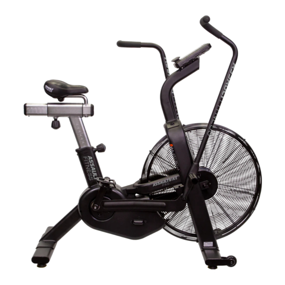
Assault Air Bike
Assembly Instructions
Tools Needed:
Box Cutter
6mm Hex Wrench
Phillips Screw Driver
13mm Wrench
22mm Wrench
15mm Wrench
Step 1: Lay the Assault Airbike Bike box on
the ground.
Step 2: Cut the straps and open the
bottom of the box.
Step 3: Stand the box up with the open
end down.
Step 4: Remove the box.
Advertisement
Table of Contents

Related Manuals for Assault Fitness Air Bike


Summary of Contents for Assault Fitness Air Bike
-
Page 1: Assembly Instructions
Assault Air Bike Assembly Instructions Tools Needed: Box Cutter 6mm Hex Wrench Phillips Screw Driver 13mm Wrench 22mm Wrench 15mm Wrench Step 3: Stand the box up with the open Step 1: Lay the Assault Airbike Bike box on end down. - Page 2 Step 5: Remove all of the protective Step 7: Place the Red tube underneath foam and plastic, and lay out all of the the frame to prop the front end of the included parts. bike up. Locate two #58 Screws, two #34 Lock washers, and two #35 Flat washers.
- Page 3 Step 8: Install the front stabilizer. Step 10: Using the red tube now prop up the rear of the bike to allow for easier installation of the rear stabilizer. Step 9: Using the provided 6mm Allen wrench, tighten the two #58 Locate two #58 Screws, two #34 Lock Screws, two #34 Lock washers, and washers, and two #35 Flat washers.
- Page 4 Step 11: Using the provided 6mm Allen Step 13: Route the Speed Sensor wrench, tighten the two #58 Screws, two cable through the console mast. #34 Lock washers, and two #35 Flat washers to secure the rear stabilizer bar. Step 14: Pull the Speed Sensor cable so Step 12: Locate the speed sensor wire there is no slack in the cable.
- Page 5 Step 15: When installing the Computer Step 16: Using the provided 6mm Allen Mast make sure the Speed Sensor Cable wrench, tighten the two #58 Screws, two does not get pinched between the frame #34 Lock washers, and two #35 Flat and the mast.
- Page 6 Step 18: Install the male and female Step 20: When installing the Computer Speed Sensor connections and make Console, tuck the excess length of Speed sure they are completely pressed into Sensor cable into the Computer Mast. place. Step 21: Using the provided multi-tool Step 19: Using the provided multi-tool reinstall the four Phillips screws onto the remove the four Phillips screws from the...
- Page 7 Step 22: Remove the Zip Ties and Step 24: Install the Handle Bar protective foam from the Left and Right Assemblies by rotating the peg sides of the bike that are securing the Clockwise. NOTE: Make sure they are Pedal Support Tubes. being threaded on straight and are not being cross-threaded.
- Page 8 Locate two #37 Pivot Pins, four #84 Step 27: Once the #37 Pivot Pin and washers and two #85 locknuts. #84 washer onto the handlebar install the linkage arm. Step 28: Once the #37 Pivot Pin is Step 26: Install the #37 Pivot Pin and inserted into the linkage arm install the #84 washer onto the handlebar.
- Page 9 Step 29: Using the provided multi tool Step 30: Using the provided 6mm and 6mm Allen wrench tighten the wrench, remove the 6mm Allen screw #37 pivot pin and #85 Locknut. When and washer from the Seat post tight make sure there is no extra Assembly.
- Page 10 Step 32: Using the provided multi-tool Step 34: Install the #16 Left pedal onto tighten both 13mm nuts on either side Left crank arm by threading it loosely of the seat. NOTE: Make sure to tighten COUNTER-CLOCKWISE and then use the both of these nuts evenly to prevent any Multi-tool to tighten it the rest of the unwanted movement.
Need help?
Do you have a question about the Air Bike and is the answer not in the manual?
Questions and answers