Dell EqualLogic PS4110 Hardware Owner's Manual
Storage arrays
Hide thumbs
Also See for EqualLogic PS4110:
- User manual (20 pages) ,
- Hardware manual (50 pages) ,
- Overview (7 pages)
Table of Contents
Advertisement
Advertisement
Table of Contents
Troubleshooting

Related Manuals for Dell EqualLogic PS4110


Summary of Contents for Dell EqualLogic PS4110
- Page 1 PS4110 Storage Arrays Hardware Owner's Manual Version 1.0...
- Page 2 All trademarks and registered trademarks mentioned herein are the property of their respective owners. Information in this document is subject to change without notice. Reproduction in any manner whatsoever without the written permission of Dell is strictly forbidden. Published February 2013...
-
Page 3: Table Of Contents
Table of Contents 1 Basic Storage Array Information Notes, Cautions, and Warnings Recommended Tools Chassis Types Array Features Back-Panel Features and Indicators Shutting Down and Restarting an Array 2 Maintaining Drives About Drive Types Identifying Failed Drives Interpreting Drive LEDs Array Behavior When a Drive Fails Drive Handling Requirements Drive Installation Guidelines and Restrictions... -
Page 5: Basic Storage Array Information
1 Basic Storage Array Information This chapter includes information about the location and basic operation of the replaceable components in a storage array, tools and equipment you will need, protecting hardware from electrostatic discharge, and power on and off operations. Notes, Cautions, and Warnings A NOTE indicates important information that helps you make better use of your system. -
Page 6: Chassis Types
Hardware Owner's Manual 1 Basic Storage Array Information Protecting Hardware Protect a PS Series array from electrostatic discharge. When handling array hardware, make sure you use an electrostatic wrist strap or a similar form of protection. To use a wrist strap: 1. - Page 7 Hardware Owner's Manual 1 Basic Storage Array Information Removing the Bezel The steps for removing the bezel are the same for all array models. 1. Using the bezel key, unlock the bezel. 2. Holding the bezel, lift the latch on the left side of the bezel and swing the left side away from the array. 3.
- Page 8 Hardware Owner's Manual 1 Basic Storage Array Information Table 1 describes the front panel features. Figure 3: Front Panel Features and Indicators (3.5-inch Drives) Figure 4: Front Panel Features and Indicators (2.5-inch Drives) Table 1: Front Panel Feature Descriptions Item Indicator Icon Description The array status LED lights when the array power is on.
-
Page 9: Back-Panel Features And Indicators
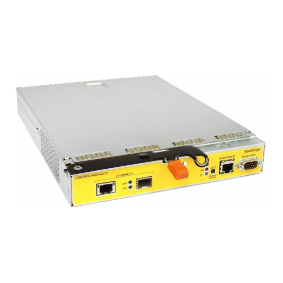
Hardware Owner's Manual 1 Basic Storage Array Information Back-Panel Features and Indicators The back of a PS4110 is shown in Figure Table 2 describes the back panel features. Figure 5: Back Panel-Features Table 2: Array Back Panel Features Item Feature Identifier Description The power switch controls the power supply output to the... - Page 10 Password: Welcome to Group Manager Copyright 2001-2011 Dell, Inc. group1> shutdown If you are using a serial connection to shut down an array, it is safe to turn off power when the “press any key” message appears. (Pressing any key will restart both control modules.) If you are using a network connection, the session will be disconnected before the array is fully shut down.
-
Page 11: Maintaining Drives
Drives are connected to a backplane through drive carriers and are hot-swappable. Drives are supplied in a carrier that is keyed to fit into specific array models, and cannot be installed in other Dell arrays, or arrays not from Dell Inc. Identifying Failed Drives A drive failure is indicated by: •... -
Page 12: Interpreting Drive Leds
Hardware Owner's Manual 2 Maintaining Drives Interpreting Drive LEDs The LEDs on a 3.5-inch drive are shown in Figure 6. The LEDs on a 2.5-inch drive are shown in Figure 7. Drive LED states are described in Table Figure 6: LEDs on 3.5-inch Drives Figure 7: LEDs on 2.5-inch Drives Table 4: Drive LED States Description... -
Page 13: Array Behavior When A Drive Fails
Hardware Owner's Manual 2 Maintaining Drives Array Behavior When a Drive Fails How an array handles a drive failure depends on whether a spare drive is available and whether the RAID set containing the failed drive is degraded. For example: •... -
Page 14: Drive Installation Guidelines And Restrictions
Hardware Owner's Manual 2 Maintaining Drives Drive Installation Guidelines and Restrictions • Replace a failed drive as soon as possible to provide the highest availability. • Install only drives of the same type, speed, and spin rate in an array. •... - Page 15 Hardware Owner's Manual 2 Maintaining Drives Figure 8: Removing a 2.5-Inch Drive Installing a 2.5-inch Drive The 2.5-inch drives are installed vertically, with the drive release latch on the top and the drive label on the bottom. 1. Wear electrostatic protection when handling a drive. See "Protecting Hardware "...
- Page 16 Hardware Owner's Manual 2 Maintaining Drives 4. Push the drive completely into the slot (callout 2). The drive handle will begin to close onto the drive (callout 5. Push in the handle until you hear a click (callout 4). Figure 9: Installing a 2.5-inch Drive Verify that the new drive is operational by examining the LEDs on the front panel, as described in Interpreting Drive LEDs on page...
- Page 17 Hardware Owner's Manual 2 Maintaining Drives 2. Press the release button (callout 1 in Figure 10). The drive latch opens and the drive emerges partway from the array (callout 2). 3. Pull the drive out by the handle until it is free of the drive bay (callout 3). Figure 10: Removing a 3.5-Inch Drive Installing a 3.5-inch Drive The 3.5-inch drives are installed horizontally, with the drive release latch to the left and the drive label to the...
- Page 18 Hardware Owner's Manual 2 Maintaining Drives 3. Hold the drive by the carrier and slide the drive most of the way into a slot (callout 1 in Figure 11). 4. Push the drive completely into the slot (callout 2). The drive handle will begin to close onto the drive (callout 5.
- Page 19 Hardware Owner's Manual 2 Maintaining Drives 1. Remove the bezel. See Removing the Bezel on page 2. Press the release tab and slide the drive blank out until it is free of the drive bay. See Figure 12 Figure Figure 12: Removing and Installing a 3.5-Inch Hard-Drive Blank Figure 13: Removing and Installing a 2.5-Inch Hard-Drive Blank Item Description...
-
Page 21: Maintaining Control Modules
3 Maintaining Control Modules Different PS Series array models contain different control module types. The combination of chassis type, control module pair, and drives determines the PS Series array model number. The control modules in a PS Series array contain the PS Series firmware which provides the Group Manager GUI, the command line interface, and all the array and storage management functions and features. - Page 22 A single control module is a single point of failure. If the control module fails, the entire array (and all the volumes on it) becomes unavailable. Dell strongly recommends buying an array with two control modules, or installing a second control module in a single-controller array.
- Page 23 Hardware Owner's Manual 3 Maintaining Control Modules Figure 14: Recommended Network Configuration to Support Vertical Failover If a network port is available for failover on either control module, but is not currently in use, its LEDs Note: will not be lit. Interpreting Control Module LEDs Control modules have the following LEDs: •...
- Page 24 Hardware Owner's Manual 3 Maintaining Control Modules Table 5: Ethernet and Management Port LED Descriptions 10GBASE-T Ethernet State Description LED Location No power, not connected to network, or passive. Left (Link) Connected to network. No power, not transmitting, or not receiving. Right (Act) Transmitting or receiving.
- Page 25 Hardware Owner's Manual 3 Maintaining Control Modules • Group Manager GUI and CLI output. The Member Controllers window or the member select show con- command output shows the control module status trollers not installed When viewed from the rear of the array, CM0 is on the top, and CM1 is on the bottom. See Front-Panel Features and Indicators on page If a control module fails, contact your PS Series support provider for a replacement.
- Page 26 Hardware Owner's Manual 3 Maintaining Control Modules Caution: In a dual control module array, both control modules must be running the same firmware version; other- wise, only one control module will be functional. When you update the array firmware, both control modules are updated to the same firmware version.
- Page 27 Hardware Owner's Manual 3 Maintaining Control Modules Figure 16: Standby Button Location Enabling the Standby Feature To use the standby button, a group administrator must enable the feature in the Group Manager GUI or CLI. Enabling the use of the button applies group-wide; that is, it allows you to press the button to shut down any member (array) that has the button (currently PS4100, PS4110, PS6100, and PS6110 array models only).
-
Page 28: Replacing A Control Module
Hardware Owner's Manual 3 Maintaining Control Modules Important Considerations Use this button only in when you must shut down a member fast, in situations where you do not have access to the Group Manager GUI or CLI. In standby mode, any volumes that use space on that member or that are bound to that member become Caution: unavailable! All operations on the member are suspended, there is no I/O activity to or from the member, and the member's... - Page 29 Hardware Owner's Manual 3 Maintaining Control Modules Control Module Replacement Procedures This section describes the procedures for removing and replacing one or both control modules in your PS Series array. The following replacement scenarios are covered: • Replacing the secondary control module in an array. •...
- Page 30 Hardware Owner's Manual 3 Maintaining Control Modules 3. Replace the control module that is now secondary (was active before the restart). (As described in Replacing the Secondary Control Module on page 25.) Replacing Both Control Modules Use the following procedure to replace both control modules in the array: 1.
- Page 31 Hardware Owner's Manual 3 Maintaining Control Modules Figure 17: Removing a Control Module (2U Array) 3. Place the control module on a flat surface where it will be protected from electrostatic charge. To avoid damage, do not place anything on top of the control module. 4.
- Page 32 Hardware Owner's Manual 3 Maintaining Control Modules Figure 18: Correct Control Module Orientation To install a control module: 1. Attach an electrostatic wrist strap, or similar protective device. See "Protecting Hardware " on page 2. Push down on the orange release tab (callout 1 in following illustration) and swing the lever (callout 2 in following illustration) out.
-
Page 33: Replacing The Microsd Card
Hardware Owner's Manual 3 Maintaining Control Modules If two control modules are installed in the array, but only one is shown in the GUI (or CLI), make sure that you have allowed enough time (minimum of five minutes) for the two control modules to boot and syn- chronize. - Page 34 Hardware Owner's Manual 3 Maintaining Control Modules 1. Firmly push the card into its housing to release the spring mechanism (callout 2 in Figure 20). The microSD card will be partially ejected from the housing. 2. Gently pull the card straight out of the housing (callout 3 in Figure 20).
-
Page 35: Advanced Networking Options
Hardware Owner's Manual 3 Maintaining Control Modules Figure 21: Inserting the MicroSD Card 3. Install the control module in the array. See Installing a Control Module on page 4. Make sure the control module is operational. See Interpreting Control Module LEDs on page Advanced Networking Options In addition to connecting all the Ethernet ports on both control modules to network switches, you can also optionally connect the Management port to a separate network switch. - Page 36 Hardware Owner's Manual 3 Maintaining Control Modules This is considered an advanced configuration, available if your environment requires this level of security. Note: Hardware Steps 1. Make sure your network environment can support a dedicated management network, with a subnet that is separate from the subnets for iSCSI traffic.
-
Page 37: Maintaining Power Supply And Cooling Modules
4 Maintaining Power Supply and Cooling Modules The array can support two hot-swappable power supply and cooling modules. The array can operate only temporarily with one module, but both modules must be present for long-term cooling of the array. About Power Supplies The PS Series array receives power from two power supplies (PSUs). - Page 38 Hardware Owner's Manual 4 Maintaining Power Supply and Cooling Modules Figure 23: 700W Power Supply LEDs Table 7: Power Supply LED Descriptions Item LED Color State ON—Normal operation. Power supply is connected to AC power and the power switch is on.
-
Page 39: Removing A Power Supply And Cooling Module
Hardware Owner's Manual 4 Maintaining Power Supply and Cooling Modules Removing a Power Supply and Cooling Module If a power supply and cooling module fails, you must replace the module as soon as possible, although an array can operate with only one working module. For proper array cooling, do not remove a failed module until you are ready to replace it. -
Page 40: Installing A Power Supply And Cooling Module
Hardware Owner's Manual 4 Maintaining Power Supply and Cooling Modules Figure 24: Removing a Power Supply and Cooling Module Installing a Power Supply and Cooling Module To install a power supply and cooling module, use the following steps and illustrations: 1. - Page 41 Hardware Owner's Manual 4 Maintaining Power Supply and Cooling Modules Figure 25: Inserting a Power Supply and Cooling Module 3. Make sure the power switch is in the OFF position. 4. Connect the power cable to the power supply and cooling module and plug the cable into a power outlet. Note: The AC LED lights up when the AC power cable is connected, even if the switches on the power supply are off.
- Page 42 Hardware Owner's Manual 4 Maintaining Power Supply and Cooling Modules Figure 26: Securing the Power Cables...
-
Page 43: Troubleshooting Your Array
Damage due to servicing that is not authorized by Dell is not covered by your warranty. Read and follow the safety instructions that came with the product. -
Page 44: Determining Service Tag Information
Hardware Owner's Manual 5 Troubleshooting Your Array Determining Service Tag Information Each array has a service tag with a number. You may need to provide this information to customer support when you contact us. • The service tag label is visible on the front of the array, on the right bezel latch block. Obtaining Component Diagnostics You can collect diagnostic information for one or more members of a PS Series group through the Group Manager GUI or the CLI. -
Page 45: Troubleshooting External Connections
Hardware Owner's Manual 5 Troubleshooting Your Array Troubleshooting External Connections • Verify that the cables are connected to the correct Ethernet and, if applicable, Management ports before trou- bleshooting any external devices. For the location of the back-panel connectors on your array, see Back- Panel Features and Indicators on page •... -
Page 46: Troubleshooting Control Modules
Hardware Owner's Manual 5 Troubleshooting Your Array • External airflow is obstructed. • The power supply and cooling module is removed or has failed. See Troubleshooting Power Supply and Cool- ing Modules on page If the problem is not resolved, see Obtaining Technical Support and Customer Service on page Troubleshooting Control Modules 1. -
Page 47: Index
Index electrostatic discharge, avoiding electrostatic wrist strap, using array control module restriction control modules cooling fans failover firmware control module LEDs failure indications power supplies control modules shutdown procedure disks fans removing PSU firmware identifying version bezel requirements installing front panel removing features control modules... - Page 48 Index: power indicators – troubleshooting power indicators power supplies removing PS Series array protecting from discharge recommended tools removing 3.5-inch drive drive blank requirements control modules cooling disks firmware power safety shutting down an array status control modules troubleshooting connections cooling problems external connections hard drives...