Table of Contents
Advertisement
Advertisement
Table of Contents

Related Manuals for REV Robotics Expansion Hub


Summary of Contents for REV Robotics Expansion Hub
- Page 1 EXPANSION HUB GUIDE Expansion Hub Guide – Rev 4 © REV R obotics, LLC 2017...
-
Page 2: Table Of Contents
Required Materials ....................................7 System Wiring Diagram ..................................8 Driver Station and Robot Controller Pairing ............................ 8 Robot Configuration....................................8 Adding an Additional Expansion Hub ..............................12 LED Blink Codes ......................................15 INTEGRATED SENSORS ....................................17 LEGACY SENSOR SUPPORT ..................................17 Level Shifter ......................................17 Connnecting a 5V Motor Encoder ..............................18... -
Page 3: Overview
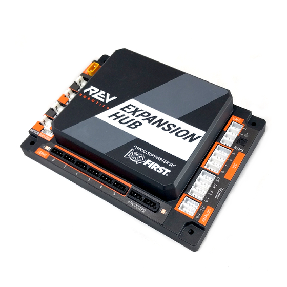
Android Phone or the REV Robotics Control Hub) to provide the interfaces required for building robots and other mechatronics. The Expansion Hub was purposed built to stand up to the rigors of the classroom and competition field. It features a mature firmware designed for basic and advanced use cases with the ability to be field upgraded in the future. -
Page 4: Port Pin Outs
1.2 Port Pin Outs Expansion Hub Guide – Rev 4 © REV R obotics, LLC 2017... -
Page 5: Protection Features
Most teams will want to use premade cables which can be sources from the REV Robotics website directly ( Table 1) for convenience, but teams can also make their own cables. -
Page 6: Jst Vh - Motor Power
1.4.2 JST VH – Moto r Po wer Motor Power connections on the Expansion Hub use the JST VH style connector. This connector is keyed and locking with a small latch (Figure 1) which must be depressed to release the cable. -
Page 7: Jst Ph - Sensors And Rs485
The JST PH style connector is used for motor encoder, analog, digital, I2C, RS485, and UART connections on the Expansion Hub. These are all 4-pin connections except for the RS485 and UART which are 3 pin. The connectors are keyed (they only insert in one orientation) and are friction locking. In Figure 2 the keying feature aligned with the cable is shown. - Page 8 Header, JST PH, 4-pin, Side Entry S4B-PH-K-S 455-1721-ND Housing, JST PH, 3-pin PHR-3 455-1126-ND Header, JST PH, 3-pin, Top Entry B3B-PH-K-S 455-1705-ND Header, JST PH, 3-pin, Side Entry S3B-PH-K-S 455-1720-ND Connector Datasheet: http://www.jst-mfg.com/product/pdf/eng/ePH.pdf Expansion Hub Guide – Rev 4 © REV R obotics, LLC 2017...
-
Page 9: Quick Start
* Other FTC legal part numbers exist. Optional Additional Materials needed to Connect an Additional Expansion Hub: • Expansion Hub (REV-31-1153) XT30 Extension Cable • Communication Cable (RS-485) • Expansion Hub Guide – Rev 4 © REV R obotics, LLC 2017... -
Page 10: System Wiring Diagram
2.4 Robot Configuration Every device connected to the Expansion Hub will need to be added to the Robot Configuration file before you can use the device in your program. The Robot Configuration will allow you to give your se nsors and actuators meaningful names that you can reference while programming. - Page 11 Configuring Your Robot for the First Time 2.4-1. Connect your Robot Controller Phone via USB to the Expansion Hub’s mini USB port. It’s also recommended to connect a battery. 2.4-2. Select the menu on either the Driver Station or Robot Controller. Then select “Configure Robot”.
- Page 12 This is the name that you will use when you are programming your robot to control this motor. Always use descriptive names so that you can remember what a device does when you are programming. Expansion Hub Guide – Rev 4 © REV R obotics, LLC 2017...
- Page 13 2.4-10. Press done once to go back to the list of device port and then select I2C Bus 0. 2.4-11. Add the built-in REV Expansion Hub IMU. Name it “imu” 2.4-12. Press the “Done” button (at the top left corner of the page) 3 times.
-
Page 14: Adding An Additional Expansion Hub
2.5 Adding an Additional Expansion Hub If you want to use more than 4 motors or 6 servos, you will need to add the Expansion Hub to your robot. An Expansion Hub can be added to another Expansion Hub or to a Control Hub. The Expansion Hub has all of the same ports as the Control Hub but without the wireless capability. - Page 15 Adding an Expansion Hub to your Robot 2.5-1. To add an additional Expansion Hub to your robot, each hub must have a unique address. Expansion Hubs come from the factory with the default address: 2. With the Robot Controller Phone connected...
- Page 16 Expansion Hubs. 2.5-6. From the Driver Station or Robot Controller app choose “Configure Robot” 2.5-7. Select “New” in the top left hand corner. Expansion Hub Guide – Rev 4 © REV R obotics, LLC 2017...
-
Page 17: Led Blink Codes
Configure and program as necessary. 2.6 LED Blink Codes The RGB LED located on the Expansion Hub near the RS485 ports provides user feedback regarding the status of the Expansion Hub. Reference Table 7 and Table 8 for different firmware LED codes. - Page 18 Blinking Blue Anytime resumes. Battery Voltage is lower than 7V. Either the 12V battery needs to be charged, or the Expansion Hub is running on USB power only. This fault will clear when battery voltage is raised above Blinking Orange Anytime This will not be overwritten by the keepalive timeout pattern.
-
Page 19: Integrated Sensors
Expansion Hub system. The REV Robotics Level Shifter is a PCB which generates a 5V output from the 3.3V input and uses a MOSFET on each signal line to create a bidirectional communication appropriate for a variety of digital signals include I2C communication (Figure 5). -
Page 20: Connnecting A 5V Motor Encoder
If using the Sensor addon cable, connect the sensor to the Expansion Hub as shown in Figure 7. It is recommended to zip tie the connection between the sensor and the sensor cable to prevent accidental disconnects. -
Page 21: Sensor Compatability Chart
4.4 Sensor Compatability Chart To determine if your existing sensors can be used with the Expansion Hub and what additional hardware if any is required, reference Table 9. Table 9: Sensor Compatibility Table Sensor Type Compatible Adapters Needed Absolute Orientation IMU Fusion Breakout - BNO055 3.3V Compatible... - Page 22 Standard Motor Kit Quad 50-0001 Encoder MATRIX Max Motor Shaft Encoder Kit Quad W38000 Encoder Tetrix Limit Switch No Adapter Needed 45-2401 Digital Custom Wiring Harness Needed Modern Robotics Expansion Hub Guide – Rev 4 © REV R obotics, LLC 2017...
- Page 23 No Adapter Needed 45-2007 Analog Custom Wiring Harness Needed Modern Robotics Light Sensor 45-2015 Analog Not Officially Supported Modern Robotics Magnetic Sensor 45-2020 Analog Not Officially Supported Modern Robotics Expansion Hub Guide – Rev 4 © REV R obotics, LLC 2017...
-
Page 24: Dimensions
5 Dimensions Expansion Hub Guide – Rev 4 © REV R obotics, LLC 2017... - Page 25 Added compatibility details on REV motors Added IMU Location and orientation to the dimension drawing • Rev 4 11/13/2017 Added LED color code table for firmware 1_07_00 • Expansion Hub Guide – Rev 4 © REV R obotics, LLC 2017...
Need help?
Do you have a question about the Expansion Hub and is the answer not in the manual?
Questions and answers