Table of Contents
Troubleshooting

Related Manuals for Duplo DocuCutter CC-229


Summary of Contents for Duplo DocuCutter CC-229
- Page 1 DocuCutter CC-229 Service and Parts Manual Revision Date: 09/16/18 Before operating the machine, read this manual. Follow all safety precautions. Duplo USA Corporation 3050 S. Daimler St, Santa Ana, CA 92705 www.duplousa.com...
- Page 2 Revison History Date Change/Add/ Reason Technical Bulletin Delete Page 06/25/18 1. Add A die module to do crease/Perf/Emboss job 2. Change Model change from CC-228 to CC-229 - 1 -...
-
Page 3: Declaration Of Conformity
Declaration of Conformity PrintFinishing Co. Ltd., located at 625 Sec. II, Wende Road, Hsin-Pu, Hsin-Chu 30544, Taiwan declares that the product compliances with the provision defined in the regulations as below. Regulation UL / CSA Low Voltage Directive Electromagnetic 2006/95/EC Compatibility Product Name Model... - Page 4 Conformity of FCC Class A This equipment has been tested and found to comply with the limits for a Class A digital device, pursuant to part 15 of the FCC Rules. These limits are designed to provide reasonable protection against harmful interference when the equipment is operated in a commercial environment.
-
Page 5: Table Of Contents
Contents SAFETY PRECAUTIONS ............................5 WEEE Informations ............................. 6 Precautions in Maintenance and Handling ......................7 Introduction ................................ 8 Specifications ..............................8 Electric Connections – Main Board ........................9 Sensor Location and Trouble Shooting………………………………………………………………………………………………………..10 Electric Connections – Driver Board ......................... 11 Motor Driver Trouble Shooting Procedure…………………………………………………………………………………………………..12 Firmware Upgrade ............................ -
Page 6: Safety Precautions
SAFETY PRECAUTIONS Always observe the cautions and Batch is given below to prevent personal injury or property damage. Disposal of Waste Electrical and Electronics Equipment (WEEE) This symbol (the symbol of the crossed out wheeled bin) indicates that in European countries this product should not be disposed of as household waste. -
Page 7: Weee Informations
WEEE information (for Europe) As a minimum the following substances, preparations and components has to be removed from any separately collected WEEE (Waste Electrical and Electronics Equipment). In this parts catalogue, these WEEE symbols are appended to corresponding parts in this parts catalogue. WEEE Symbol Meaning (Poly Acrylonitrile Butadiene Styrene) Plastic Material... -
Page 8: Precautions In Maintenance And Handling
Precautions in Maintenance and Handling Repairs should be performed by qualified service personnel. WARNING: 2.1 To avoid the risk of touching to any hot spot on UV Curing section to cause injury, system has to be cool down before performing any services procedure in curing section. 2.2 To avoid the risk of electrical shock, disconnect the machine from the A.C. -
Page 9: Specifications
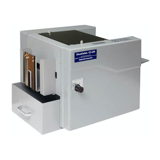
Introduction The DocuCutter CC-229 is designed to simplify business card, photo, post card cutting and creasing in letter size which printed by digital press, color laser printer or inkjet image printer in one pass. Specifications Paper Size LT / Legal Size/ 9” x 14” (Max) -
Page 10: Electric Connections – Main Board
Electric Connections – Main Board LED On LED Off while power is on and feed tray has paper Connector Connects to Connector Connects to On/OFF On/OFF Feed Tray Sensor S1 Waste Bin Switch S8 Transport Sensor S2 Rear Cover Switch S9 Top Margin/Mark Reader S3 DN10 Not in use... - Page 11 Sensor Location Pick Up Roller S5 Cutter Sensor S2 Transport Sensor S1 Feed Tray Sensor S3 Mark/Margin Sensor Sensor Trouble Shooting Procedure 1. Insert a piece of paper into 1 pick-up roller, press to move the paper forward, while paper reaches to S2, S3 and S5, the sensor LED will be on;...
-
Page 12: Electric Connections – Driver Board
Electric Connections – Driver Board Connector Connects to Connector Connects to 16-pin, Main Board CN2 4-pin, Die Module Motor 10-pin, Main Board CN6 CN10 4-pin, Cutter Motor 4-pin, 24V DC Power Supply CN11 16-pin, LCD Display 4-pin, Feed Motor CN16 10-pin, Control Panel Board 4-pin, Transport Motor - 11 -... - Page 13 Driver Board Trouble Shooting Procedure Value+ Value- 1. Hold simultaneously for 2 seconds into Burn-in Test Mode 2. Press to activate Feeder Motor, if feed motor does not move, replace driver board Value+ 3. Press to activate Transport Motor, if motor does not move, replace driver board 4.
-
Page 14: Firmware Upgrade
Firmware Upgrade 1. Power off 2. Using an adaptor board as shown below: 2.1 10-pin cable to CN 1 on main board and USB connector to USB port on Note Book 3. Power On Firmware Upgrade Adaptor Board P/N 883-020-051A 4. - Page 15 4.3 After install the software Uniflash. Please connect the EVM board (EPROM writer) and target board. Double click the shortcut icon on the desktop to start. 4.4 “Choose Your Device” at Category “Tiva” - 14 -...
- Page 16 4.4 Choose the MCU “TM4C123GH6PZ” 4.6 Choose Your Connection at “Stellaris In-Circuit Debug Interface” - 15 -...
- Page 17 4.7 Click “START” to browse the file need to be upgrade. 4.8 Browse the file need to be upgrade. - 16 -...
- Page 18 4.9 Click the “Load Image” icon to load the image file to the target board. 4.10 After load the image file successfully. The information line will show “<success>Program Load completed successfully”. Then you can hear the machine will initialize automatically. - 17 -...
-
Page 19: Calibrations
Calibrations Value+ Value- Batch 1. Hold at same time for 2 seconds into Calibration mode 2. Press one time the cursor will be move down or up one factor accordingly Margin: Top margin Offset: Last card is too long or to short to compensate Mark: Cutting Mark Leng: Card Length... - Page 20 Paper Weight Press into Paper Weight setting mode, then press to do selection Setting Paper Weight 1, 2 120 – 210 (gsm) 211 – 300 (gsm) 4, 5 301 – 350 (gsm) - 19 -...
-
Page 21: Top Margin Parallel Adjustment
Top Margin Parallel Adjustment 1. Power off 2. Remove the rear cover 3. Using a 300gsm or 14 pt. sheet as gauge, rotate the feed roller by hand to feed it into apex of registration roller firm. 4. Underneath the feed tray has 5.5mm nut to hold the side guide, loosen the nut and align it against the paper to make it straight. -
Page 22: Error Message And Trouble Shooting
Error Message and Trouble Shooting Error Message/Symptom Trouble Shooting Paper Out 1. Feed Tray is empty 2. Check S1 refer to page 8 and 9 3. Is feed motor belt broken? If not, 4. Check pulley screw loose, if not 5. - Page 23 Slitting not good Replace the slitter No Power 1. Check Fuse 2. Check power plug 3. Check main board has 5/24V or power supply has 5/24V Paper buckled at feed ramp 1. Adjust the feed tray tension spring position 2. Set paper weight according the paper weight - 22 -...
-
Page 24: Explosive View And Weee
Explosive View and WEEE (Fig.1) Name Q’TY 883-010-000A Asm, Side Plate, Non-Operating 883-020-000A Asm, Side Plate, Operating 883-030-000A Asm, Electric Panel 883-040-000A Cover, Front Safety 883-050-000A Asm, Feed Table 881-G00-000A Bar, 883-070-000A Asm, Feed Ramp 881-N00-000A Asm, Feed Roller 881-N10-000A Asm, Transport Roller, Lowe, Front 881-N20-000A Asm, Transport Roller, Lower, Middle... - Page 25 - 24 -...
- Page 26 883-010-000A Non-Operating Side Plate Asm (Fig. 2) Name Q’TY 883-010-010A Side Plate, Right 00R-000-1101 Rubber Foot 00B-000-0905 Angle Bracket 881-A04-000A Stopper 00M-000-0427 Motor, 103H7823-1760 881-708-0000 Crank, Knife Driving 881-405-040A Bushing, OD9, ID6.2 00B-000-1260 Ball Bearing, L-1260ZZ 883-010-090A Idler 00B-000-1680 Ball Bearing, L-1680ZZ 00S-000-5904 Standoff, Idler 00N-000-0012...
- Page 27 - 26 -...
- Page 28 883-020-000A Operating Side- Side Plate Asm (Fig. 3) Name Q’TY 883-020-010A Side Plate, Left 00R-000-1101 Rubber Foot 00B-000-0905 Angle Bracket 881-B04-000A Stopper 883-020-050A Main Board 883-020-051A Adaptor Board, Firmware Upgrade 00M-000-0401 Motor, CKM245-01AH 02P-17G-0500 Pulley, 0.2 P, 17G, ID 5.00 00B-MXL-132C Belt, 0.2P, 132MXL, 8mm 00M-000-0427...
- Page 29 00B-000-0943 Bracket, Interlock Switch Mounting 00S-000-6105 Switch, Interlock, 00W-883-2233 Wire, 33cm, 22AWG Housing, Female, 2-pin 2PH-716-102F 883-020-232A Asm, Interlock Switch, Rear Cover 00B-000-0943 Bracket, Interlock Switch Mounting 00S-000-6105 Switch, Interlock 00W-883-2257 Wire, 57cm, 22AWG Housing, Female, 2-pin 2PH-716-102F 883-020-233A Asm, Interlock Switch, Waste Bin 00B-000-0943 Bracket, Interlock Switch Mounting 00S-000-6105...
- Page 30 - 29 -...
- Page 31 883-030-000A Electric Panel Asm (Fig. 4) Name Q’TY 883-030-010A Plate, Electric Panel, CC-229 883-030-020A Power Supply, 24V, RSP-320-24 00B-PWR-010A Bracket, Power Supply PCBA 883-030-040A Driver Board Not in Use Cover, Dust, Driver Board - 30 -...
- Page 32 883-050-000A Feed Tray Asm (Fig. 5) Name Q’TY 881-211-000B Tray, Feed, CC-228 881-E02-000A Shaft, Side Guide Sliding Bracket, Side Guide Mounting 881-E03-000A Standoff, 6.35 x 2.2mm 00S-000-5901 Side Guide, Feeder, CC-228 881-105-000B 881-215-000A Thumb Screw, Feeder Side Guide 881-406-000A Shaft, Pivot, Feed Tray 881-217-000A Bracket, Feed Tray Mounting 881-212-000B...
- Page 33 Fig. 5 - 32 -...
- Page 34 883-070-000A Feed Ramp Asm Name Q’TY 881-116-000A Ramp, Feed 881-F01-010A Plate, Ramp, Feed 881-F01-020A Paper Registration 00B-000-0905 Angle Bracket 881-F03-000A Asm, Separator 881-F03-010A Base, Separator Asm 881-F03-020A Lower Limit Plate, Separator 881-F03-030A Pin, Separator Compression Spring Holding 881-F03-040A Shaft, Pivot, Separator Holding Plate 881-F03-050A Holder, Separator 881-F03-060A...
- Page 35 - 34 -...
- Page 36 Feed Roller Asm (Fig. 7) Name Q’TY 881-N01-000A Shaft, Feed Roller 00B-0UF-L001 Pillow Block Ball Bearings, UFL-001 00R-000-1502 Feed Roller, CC-228 881-N03-000A Core, Feed Roller 00R-010-520A Feed Roller 881-N04-000A Shaft, Feed Driving 162-107-0400 Bushing, OD7, ID6(162-107-0400) 00B-000-6201 Ball Bearing, 6201ZZ 881-N07-000A Housing, Ball Bearing 6201ZZ 881-N12-000A...
- Page 37 Front Lower Trasport Roller Asm (Fig. 8) Name Q’TY 881-H01-000A Roller, Transport, CC-228 00G-M10-1910 Gear, M1, 19T, ID10 00B-00F-1980 Ball Bearing, LF-1980ZZ Collar, OD16, ID 8 00C-000-1205 02P-51G-08WK Pulley, 0.2 P,51G, ID 8-WK 02P-51G-080A Pulley, 0.2 P,51G, ID 8 00E-M08-000E E-Ring, 8mm Fig.
- Page 38 Middle Lower Trasport Roller Asm (Fig. 9) Name Q’TY 881-H01-000A Roller, Transport, CC-228 00G-M10-1910 Gear, M1, 19T, ID 10 00B-00F-1980 Ball Bearing, LF-1980ZZ Collar, OD16, ID 8 00C-000-1205 02P-51G-08WK Pulley, 0.2 P,51G, ID 8-WK 00B-MXL-099C Belt, 0.2P, 99MXL, 8mm 00E-M08-000E E-Ring, 8mm 00B-MXL-132C Belt, 0.2P, 132MXL, 8mm...
- Page 39 Rear Lower Transport Roller Asm (Fig. 10) Name Q’TY 881-H01-000A Roller, Transport, CC-228 00G-M10-1910 Gear, M1.0, 19T, ID10 00B-00F-1980 Ball Bearing, LF-1980zz Collar, OD16, ID8 00C-000-1205 02P-51G-080A Pulley, 0.2, P51G, ID 8 00E-M08-000E E-Ring, 8mm Fig. 10 - 38 -...
- Page 40 Front UpperTransort Roller Asm (Fig. 11) Name Q’TY 881-L01-000B Roller, Upper, Transport 00G-M10-1910 Gear, M1, 19T, ID10 Nylon Graphite Gasket, OD14, ID8.2 881-L03-000A Nylon 883-120-040A Rocker Asm 00H-000-1280 Housing, 1280 Ball Bearing, Transport Rocker 00B-00F-1280 Ball Bearing, LF-1280ZZ 00B-000-1280 Ball Bearing, L-1280ZZ - 39 -...
- Page 41 Rear Upper Transnsport Roller Asm (Fig. 12) Name Q’TY 881-M01-000B Roller, Transport 00G-M10-1910 Gear, M1.0, 19T, ID10 Nylon Graphite Gasket, OD14, ID8.2 881-L03-000A Nylon 883-120-040A Rocker Asm 00H-000-1280 Housing, 1280 Ball Bearing, Transport Rocker 00B-00F-1280 Ball Bearing, LF-1280ZZ 00B-000-1280 Ball Bearing, L-1280ZZ Fig.
- Page 42 883-140-000A Die Module Fine Tuning Asm (Fig. 13) {Need to add a Mark Reader} Name Q’TY 883-140-010A Bar, Die Module Fine Tuning 883-140-020A Bracket, Die Module Sensor Mounting 883-070-060A Asm, Paper Sensor 00S-00E-ESB5 Sensor, EE-SB5 00W-883-2463 Wire, 63cm, 24 AWG Housing, Female, 2-pin 2PH-716-102F 883-140-040A...
- Page 43 883-150-000A Die Module (Fig. 14) Name Q’TY 883-150-010A Bracket, Die Module 883-150-020A Sie Plate, Die Module 881-R17-000A Handle 883-150-040A Thumb Screw 00E-M04-000E E-Ring M4 883-150-060A Bracket, Lower Die Base Mounting 883-150-070A Base, Lower Die 00M-000-0002 Magnet, Rear Cover Position 883-150-090A Pin, ψ4*6, Die Plate Positioning 00B-0LM-06UU Linear Bearing, LM-06-UU...
- Page 44 - 43 -...
- Page 45 881-Q00-000A Upper Knife Driving Asm (Fig. 15) Name Q’TY 881-704-000A Knife, Upper. CC-228 881-P02-000A Plate, Upper K NIFE OUNTING 881-719-000A Link 881-701-000A Bushing, OD7.9, ID6.1 881-P05-000A Shaft, Knife Driving 00B-00F-1910 Ball Bearing, LF-1910zz 881-721-000A Arm, R, Knife Driving 881-P07-010A Plate, Knife Driving 881-P07-020A Block, Arm Link 881-720-000A...
- Page 46 881-P00-000A Lower Knife Asm (Fig. 16) Name Q’TY 881-711-000A Chassis, Cutting Knife Mounting CC-229 881-705-000A Knife, Lower, CC-228 881-714-000A Asm, Middle, Upper Knife Holding Spring 881-714-010A Spring, Middle, Upper Knife Holding Spring 881-714-020A Pin, Middle, Upper Knife Holding Spring 881-714-030A Bushing, Middle, Upper Knife Holding Spring 00B-000-L940 Ball Bearing, L940ZZ...
- Page 47 - 46 -...
- Page 48 883-180-000A Slitter Mounting Chassis Asm (Fig. 17) Name Q’TY 883-180-010A Chassis, Slitting Module Mounting , CC-229 881-S02-000A Stud, Rear Safety Cover 00M-000-0002 Magnet, Rear Cover Position 883-180-040A Thumb Screw, Slitting Module Fastening CC-229 881-111-010A Spring, Compression, Slitting Module Fastening 00E-M08-000E E-Ring, 8mm 00W-M05-000F FLAT WASHER M5...
- Page 49 883-190-000A Slitter Left/Right Adj Asm (Fig. 18) Name Q’TY 883-190-010A Nut, Slitter Left/Right Adj 883-190-020A Screw, Driving, Slitter Left/Right Adj 00B-00F-1260 Ball Bearing, LF-1260zz 00C-000-1606 Collar, OD16, ID 6 883-190-050A Block, Slitter Fine Tune Adjustment Holding 883-190-060A Ball Steel, Pressure Holding 883-190-060B Spring, Ball Screw Pressure Holding 00S-M04-006S...
- Page 50 Slitter Asm (Fig. 19) Name Q’TY 881-801-000A Chassis, Slitter, 2 x 3.5” 881-801-010A Chassis, Slitter, 5.47X 4.21” 881-803-000A Side Plate, L, Slitter 881-802-000A Side Plate, R, Slitter 881-805-000A Shaft, Slitter, Lower 881-804-010A Shaft, Slitter, Upper, 2x3.5” Slitter 881-804-020A Shaft, Slitter, Upper, 5.47x4.21” Slitter 881-807-000A Slitting Wheel, Center Gutter, 0.5”...
- Page 51 Fig. 19 - 50 -...
- Page 52 883-021-000A Top, Safety Cover Asm (Fig. 18) Name Q’TY 883-021-010A Top, Safety Cover 883-021-020A Bracket, Top Cover 883-021-030A Trigger, Top Cover Fig. 18 - 51 -...
- Page 53 Rear, Safety Cover Asm 883-220-000A (Fig. 19) Name Q’TY 883-220-010A Rear, Safety Cover , CC-229 883-220-020A Catcher 881-109-1000 Asm, Divider 881-109-1000-0A Plate, Divider 881-109-1000-0B Flexible Magnets 75 * 18 Fig. 19 - 52 -...
- Page 54 Waste Bin Asm 883-250-000A (Fig. 20) Name Q’TY 883-250-010A Waste Bin , CC-229 00A-000-220A Index, Waste Bin 881-R17-000A Handle Fig. 20 - 53 -...
-
Page 55: Recommended Spare Parts List
Recommended Spare Parts List Part Number Name 00A-51G-FC12 Asm, Pulley/Clutch, 51G/FC12 Hardening Bushing, OD12, ID9(LRT-91216) 00B-000-1209 00B-0UF-L001 Pillow Block Ball Bearings, UFL-001 00B-MXL-099C Belt, 0.2P, 99 MXL, 8mm 00B-MXL-132C Belt, 0.2P, 132MXL, 8mm 00D-000-0304 Display, LCD, 4 Row x 20 00M-000-0401 Motor, CKM245-01AH 00M-000-0427... - Page 56 883-030-020A Power Supply, 24V, RSP-320-24 883-030-040A Driver Board 883-050-100A Asm, Feed Tray Sensor, CC-229 883-070-060A Asm, Paper Sensor 883-112-010A Asm, Dummy Die Module 883-120-040A Rocker Asm 883-150-000A Asm, Die Module 883-150-250A Die Plate, Crease, Lower 883-150-260A Die Plate, Crease, Upper - 55 -...
Need help?
Do you have a question about the DocuCutter CC-229 and is the answer not in the manual?
Questions and answers