
Related Manuals for Chattanooga Group OPTIFLEX3 2090


Summary of Contents for Chattanooga Group OPTIFLEX3 2090
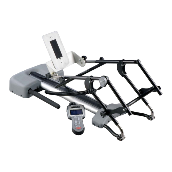
- Page 1 SERVICE MANUAL Model- 2090 Applies to Serial numbers 1000 and above ISO 13485 CERTIFIED...
-
Page 2: Table Of Contents
OptiFlex® 3 Continuous Passive Motion (CPM) Therapy Unit TABLE OF CONTENTS FOREWORD ....................... . . 1 1... -
Page 3: Foreword
©2008 Encore Medical, L.P. and its affiliates, Austin, Texas, USA. Any use of editorial, pictorial, or layout composition of this publication without express written consent from Chattanooga Group of Encore Medical, L.P. is strictly prohibited. This publication was written, illustrated, and prepared for print by Chattanooga... -
Page 4: 1 Theory Of Operation
OptiFlex® 3 Continuous Passive Motion (CPM) Therapy Unit 1 THEORY OF OPERATION 1.1 OVERVIEW The OptiFlex 3 CPM product is comprised of one Universal Power Supply and one Motor Control Board housed within the head section of the unit along with the Motor and Gearbox Assembly. These components are linked to a Pendant via a cable connection that provides the operator access for set up and operation of the unit. -
Page 5: 2 Safety Precautions
OptiFlex® 3 Continuous Passive Motion (CPM) Therapy Unit 2 SAFETY PRECAUTIONS 2.1 PRECAUTIONARY DEFINITIONS The precautionary instructions found in this E. Biohazard section and throughout this manual are indicated by specific symbols. Understand these symbols and their definitions before operating this equipment. - Page 6 OptiFlex® 3 Continuous Passive Motion (CPM) Therapy Unit 2 SAFETY PRECAUTIONS 2.2 PRECAUTIONARY INSTRUCTIONS • The lubricants and locking compounds listed in • Read, understand and practice the precautionary and this manual are crucial in the assembly of certain operating instructions found in this manual before components to ensure patient safety and efficient operating or using the unit.
- Page 7 OptiFlex® 3 Continuous Passive Motion (CPM) Therapy Unit 2 SAFETY PRECAUTIONS 2.2 PRECAUTIONARY INSTRUCTIONS (CONTINUED) • DO NOT connect the unit to an electrical • Failure to re-install and properly tighten all screws supply without first verifying that the may result in Electrical Safety System degradation power supply is the correct voltage.
-
Page 8: 3 Nomenclature
OptiFlex® 3 Continuous Passive Motion (CPM) Therapy Unit 3 NOMENCLATURE 3.1 OPTIFLEX 3 The nomenclature graphic below, Figure 3.1, Know the components and their functions before indicates the general locations of the major performing any operation of or service to the components of the OptiFlex 3 CPM unit. - Page 9 OptiFlex® 3 Continuous Passive Motion (CPM) Therapy Unit 3 NOMENCLATURE 3.2 OPTIFLEX 3 PENDANT The Pendant nomenclature graphic below, Figure 3.2, Know the components and their functions before indicates the location and functions of the OptiFlex 3 performing any operation of or service to the OptiFlex 3 CPM unit.
-
Page 10: 4 Specifications
OptiFlex® 3 Continuous Passive Motion (CPM) Therapy Unit 4 SPECIFICATIONS 4.1 OPTIFLEX 3 CPM THERAPY UNIT SPECIFICATIONS FIGURE 4.1 Input ......100-240 VAC, 50/60 Hz, 75 VA REGULATORY COMPLIANCE Weight .. -
Page 11: Description Of Device Markings
OptiFlex® 3 Continuous Passive Motion (CPM) Therapy Unit 4 SPECIFICATIONS 4.2 DESCRIPTION OF DEVICE MARKINGS The markings on the OptiFlex 3 CPM unit are your assurance of its conformity to the highest applicable standards of medical equipment safety and electromagnetic compatibility. One or more of the following markings may appear on the device: This product complies with WEEE Meets Directive 93 /42 /EEC... -
Page 12: 5 Troubleshooting
Software Error Messages bad, replace the suspected board. of the OptiFlex 3 units to “Board Level” only. No component level troubleshooting information is or will be provided by Chattanooga Group for field troubleshooting of board components. ERROR ERROR DEFINITION... -
Page 13: Optiflex 3 System Testing
OptiFlex 3 are SAE Standard. Due to the size of these 2. Due to the complex nature of the technology components, no metric equivalent is available. Therefore, utilized by Chattanooga Group, the it will be necessary to obtain the proper size tools for recommended troubleshooting techniques removal and replacement of certain components. -
Page 14: Visual Inspection
OptiFlex® 3 Continuous Passive Motion (CPM) Therapy Unit 5 TROUBLESHOOTING 5.3 VISUAL INSPECTION 5.6 ELECTRICAL SAFETY TESTS A. General Conduct all necessary Electrical Safety tests as Visually inspect the OptiFlex 3 for and visible required per your facility, local or national damage to the unit or pendant that may interfere regulatory agency. -
Page 15: Flexion Angle And Calibration Test
OptiFlex® 3 Continuous Passive Motion (CPM) Therapy Unit 5 TROUBLESHOOTING 5.7 FLEXION ANGLE & CALIBRATION TEST Specification ....... .90° ± 3° A. - Page 16 OptiFlex® 3 Continuous Passive Motion (CPM) Therapy Unit 5 TROUBLESHOOTING 7. Press and hold the Flexion button. While holding the Flexion button down, press the Up Arrow button until 90° is displayed on the Pendant. Refer to Figure 5.5. UP ARROW BUTTON FLEXION BUTTON...
-
Page 17: Travel Speed Test
OptiFlex® 3 Continuous Passive Motion (CPM) Therapy Unit 5 TROUBLESHOOTING 5.8 TRAVEL SPEED TEST 5.10 PENDANT DISCONNECT TEST Spec ..... . 0° to 90° in 60 Sec ±10% Spec . -
Page 18: 6 Removal & Replacement
OptiFlex® 3 Continuous Passive Motion (CPM) Therapy Unit 6 REMOVAL & REPLACEMENT 6.1 UNIT COVERS 2. Lift up and rotate the Rear Acess Cover toward the Carrying Handle of the unit. Slide the cover over the Carrying Handle to completely remove from the unit. -
Page 19: Manual Movement Of The Carriage
OptiFlex® 3 Continuous Passive Motion (CPM) Therapy Unit 6 REMOVAL & REPLACEMENT 6.2 MANUAL MOVEMENT OF THE CARRIAGE Unplug the unit from the power source before attempting any removal or replacement procedures to prevent electrical shock. When the unit fails electronically the carriage can be moved manually. -
Page 20: Motor Control Board
OptiFlex® 3 Continuous Passive Motion (CPM) Therapy Unit 6 REMOVAL & REPLACEMENT 6.3 MOTOR CONTROL BOARD 3. Using the #2 Phillips Screwdriver, remove the two mounting screws securing the Motor Control Board to the Base. Refer to Unplug the unit from the power source before Figure 6.3. -
Page 21: Drive Belt
OptiFlex® 3 Continuous Passive Motion (CPM) Therapy Unit 6 REMOVAL & REPLACEMENT 6.4 DRIVE BELT Unplug the unit from the power source before Failure to re-install and properly tighten all attempting any removal or replacement procedures screws may result in Electrical Safety System to prevent electrical shock. -
Page 22: Motor Assembly
OptiFlex® 3 Continuous Passive Motion (CPM) Therapy Unit 6 REMOVAL & REPLACEMENT 6.5 MOTOR ASSEMBLY Failure to re-install and properly tighten all screws may result in Electrical Safety System Unplug the unit from the power source before degradation which may cause unit damage, attempting any removal or replacement procedures malfunction, electrical shock or personal injury. -
Page 23: Power Supply
OptiFlex® 3 Continuous Passive Motion (CPM) Therapy Unit 6 REMOVAL & REPLACEMENT 6.6 POWER SUPPLY 6. Remove the two screws securing the Power Supply to the Base using a #2 Phillips screwdriver. Refer to Figure 6.8. Unplug the unit from the power source before 7. -
Page 24: Potentiometer (Knee-Pot)
OptiFlex® 3 Continuous Passive Motion (CPM) Therapy Unit 6 REMOVAL & REPLACEMENT 3. Use a #2 Phillips screwdriver to remove the 3 6.7 POTENTIOMETER (KNEE-POT) screws securing the Potentiometer Cover and remove the Cover. NOTE: Unplug the unit from the power source before When installing the Potentiometer Cover, part attempting any removal or replacement procedures number J6105, hand tighten the three... - Page 25 OptiFlex® 3 Continuous Passive Motion (CPM) Therapy Unit 6 REMOVAL & REPLACEMENT 6.7 POTENTIOMETER (CONTINUED) 7. On the rear end of the unit, press the tab on the connector attaching the Potentiometer to the Control Board and detach. 8. Turn the unit over and using a Heyco Tool, remove the Heyco securing the Potentiometer Cable to the Base.
-
Page 26: Acme Screw Ball Screw
OptiFlex® 3 Continuous Passive Motion (CPM) Therapy Unit 6 REMOVAL & REPLACEMENT 6.8 ACME ROD (BALL SCREW) NOTE: Observe the locations of the washers and bearing for installation. Inset A on page 38 details proper installation. Unplug the unit from the power source before 6. - Page 27 OptiFlex® 3 Continuous Passive Motion (CPM) Therapy Unit 6 REMOVAL & REPLACEMENT 6.8 ACME ROD (CONTINUED) 9. Remove both of the Wiper Blades by sliding 14. Using Snap Ring pliers, remove the snap out of the open end of the Frame Base. ring inside of the Frame Base to release the Ball Screw.
-
Page 28: Pendant Receptacle Cable
OptiFlex® 3 Continuous Passive Motion (CPM) Therapy Unit 6 REMOVAL & REPLACEMENT 6.9 PENDANT RECEPTACLE CABLE 3. Hold the nut inside of the unit Frame securing the Receptacle Cable. Using a pair of adjustable pliers, turn the housing on Disconnect the pendant from the unit before the outside of the unit counterclockwise to attempting any removal or replacement procedures release. -
Page 29: Pendant Cable
OptiFlex® 3 Continuous Passive Motion (CPM) Therapy Unit 6 REMOVAL & REPLACEMENT 6.10 PENDANT CABLE 4. Detach the 5 pin connector from the Control Board of the Pendant. Refer to Figure 6.22. Disconnect the pendant from the unit before attempting any removal or replacement procedures to prevent electrical shock. -
Page 30: Pendant Control Board
OptiFlex® 3 Continuous Passive Motion (CPM) Therapy Unit 6 REMOVAL & REPLACEMENT 6.11 PENDANT CONTROL BOARD NOTE: Carefully slide the Display Ribbon Cable through the slot in the Control Board when Disconnect the pendant from the unit before removing the board. Handle the Ribbon attempting any removal or replacement procedures Cable gently to avoid damage. -
Page 31: Pendant Battery
OptiFlex® 3 Continuous Passive Motion (CPM) Therapy Unit 6 REMOVAL & REPLACEMENT 6.12 PENDANT BATTERY Disconnect the pendant from the unit before attempting any removal or replacement procedures to prevent electrical shock. A. Part Number ......89870 B. -
Page 32: Upper And Lower Pendant Keymats
OptiFlex® 3 Continuous Passive Motion (CPM) Therapy Unit 6 REMOVAL & REPLACEMENT 6.13 UPPER AND LOWER PENDANT KEYMATS Disconnect the pendant from the unit before attempting any removal or replacement procedures to prevent electrical shock. A. Part Numbers Upper Keymat ......J6100 Lower Keymat . -
Page 33: Pendant Display
OptiFlex® 3 Continuous Passive Motion (CPM) Therapy Unit 6 REMOVAL & REPLACEMENT 6.14 PENDANT DISPLAY Disconnect the pendant from the unit before attempting any removal or replacement procedures to prevent electrical shock. A. Part Number ......J1123 B. -
Page 34: 7 Calibration
OptiFlex® 3 Continuous Passive Motion (CPM) Therapy Unit 7 CALIBRATION 7.1 ANGLE POTENTIOMETER POSITION C. Initial Position Calibration Procedure CALIBRATION 1. Enter the “Calibration Mode” of the Pendant The following procedure constitutes the required by pressing and holding the “Comfort calibration of the Angle Potentiometer. - Page 35 OptiFlex® 3 Continuous Passive Motion (CPM) Therapy Unit 7 CALIBRATION 7.1 ANGLE POTENTIOMETER POSITION CALIBRATION (CONTINUED) 5. With the 3/32” Allen wrench, loosen the two 8. Torque the two potentiometer set screws set screws retaining the potentiometer. with the preset 5 inch-pound “T”-Handle Refer to Figure 7.5.
-
Page 36: Force Reversal Calibration
OptiFlex® 3 Continuous Passive Motion (CPM) Therapy Unit 7 CALIBRATION 7.2 FORCE REVERSAL CALIBRATION A. Position Carriage Move the carriage to a position of -5° to -10°. B. Set Unit to Force Reversal Calibration Mode While holding down the “SPEED” button, press the following buttons in the sequence listed:... -
Page 37: 8Maintenance
OptiFlex® 3 Continuous Passive Motion (CPM) Therapy Unit 8 MAINTENANCE 8.3 FACTORY SERVICE When the OptiFlex 3 CPM unit requires factory service, contact the dealer or Chattanooga Unplug the unit from the power source before Group Service Department. attempting any removal or replacement procedures WARRANTY REPAIR/OUT OF WARRANTY to prevent electrical shock. - Page 38 OptiFlex® 3 Continuous Passive Motion (CPM) Therapy Unit MAINTENANCE 8.4 MAINTENANCE RECORDS...
- Page 39 OptiFlex® 3 Continuous Passive Motion (CPM) Therapy Unit MAINTENANCE 8.4 MAINTENANCE RECORDS CONTINUED...
-
Page 40: 9 Parts
OptiFlex® 3 Continuous Passive Motion (CPM) Therapy Unit 9 PARTS 8.1 OPTIFLEX 3 CPM THERAPY UNIT PARTS SEE- B SEE- A... - Page 41 OptiFlex® 3 Continuous Passive Motion (CPM) Therapy Unit 9 PARTS 9.1 OPTIFLEX 3 CPM THERAPY UNIT PARTS LIST ITEM PART NO. DESCRIPTION ITEM PART NO. DESCRIPTION 62066 SCREW, 1/4-20 X 5/8" 54931 PIN, SPLIT 3/32" X 5/8" PLT J1089 CLEVIS PIN, 1/4" X 1-3/8" SS J1117 FEMUR LINKAGE J1131...
- Page 42 OptiFlex® 3 Continuous Passive Motion (CPM) Therapy Unit 9 PARTS 9.2 OPTIFLEX 3 PENDANT PARTS LIST PART NO. DESCRIPTION J2038 PENDANT J6094 UPPER PENDANT CASING J6096 LOWER PENDANT CASING J6100 PENDANT KEYMAT UPPER J6101 PENDANT KEYMAT LOWER J6106 DECAL OVERLAY PENDANT J1119 SCREWS 2 X 5/16 PAN PHILLIPS J1120...
-
Page 43: 10 Schematics
OptiFlex® 3 Continuous Passive Motion (CPM) Therapy Unit 10 SCHEMATICS 10.1 BLOCK DIAGRAM LANDSCAPED... - Page 44 OptiFlex® 3 Continuous Passive Motion (CPM) Therapy Unit 10 SCHEMATICS 10.2 CONTROL BOARD 1 LANDSCAPED...
- Page 45 OptiFlex® 3 Continuous Passive Motion (CPM) Therapy Unit 10 SCHEMATICS 10.2 CONTROL BOARD 2 LANDSCAPED...
- Page 46 OptiFlex® 3 Continuous Passive Motion (CPM) Therapy Unit 10 SCHEMATICS 10.2 PENDANT LANDSCAPED...
-
Page 47: 11 Warranty
OptiFlex® 3 Continuous Passive Motion (CPM) Therapy Unit 11 WARRANTY Chattanooga Group, a division of Encore Medical, L.P. (“Company”) warrants that the OptiFlex 3 Continuous Passive Motion (CPM) therapy unit (“Product”) is free of defects in material and workmanship. This warranty shall remain in effect for two years (24 months) from the date of original consumer purchase. - Page 48 Moving Rehabilitation Forward™ MDSS GMBH Schiffgraben 41 30175 Hannover Germany Telephone:+ 49 -5103-939430 ISO 13485 CERTIFIED 4717 Adams Road P.O. Box 489 Hixson, TN 37343 U.S.A. 1-423-870-2281 1-800-592-7329 U.S.A. 1-800-361-6661 CANADA +1-423-870-7200 OUTSIDE U.S.A +1 423-870-2046 OUTSIDE U.S.A. FAX chattgroup.com J1168A ©...
Need help?
Do you have a question about the OPTIFLEX3 2090 and is the answer not in the manual?
Questions and answers