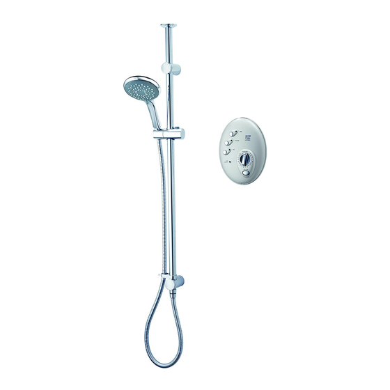
Triton T300si Installation And Operating Instructions Manual
Wireless remote electric shower
Hide thumbs
Also See for T300si:
- Installation and operating instructions manual (48 pages) ,
- Installation and operating instructions manual (32 pages)
Table of Contents
Advertisement
Advertisement
Table of Contents

Related Manuals for Triton T300si


Summary of Contents for Triton T300si
- Page 1 Installation and operating instructions The showerhead and hose supplied with this product are a safety critical part of your shower. Failure to use genuine Triton parts may cause injury and invalidate your guarantee. 2180520O - April 2017...
-
Page 2: Table Of Contents
T300si wireless remote electric shower CONTENTS Page Important safety information ............1 Introduction ................... 2 Specifications .................. 2 Advice to users ................3 Main components ................4 – 5 Electrical requirements ..............6 – 7 Battery safety guidelines ...............8 – 9 Water requirements ............... 10 Installation options ..............11 –... -
Page 3: Important Safety Information
T300si wireless remote electric shower PLEASE READ THIS IMPORTANT SAFETY INFORMATION Products manufactured by Triton are safe and without risk provided they are installed, used and maintained in good working order in accordance with our instructions and recommendations. WARNING: DO NOT operate shower if frozen, or suspected of being frozen. It must thaw out before using. -
Page 4: Introduction
Complies with the requirements of the Radio and Telecommunications Terminal Equipment (RTTE) Directive 1999/5/EC. To check the product suitability for commercial and multiple installations, please contact Triton’s speci cation advisory service before installation. Please see back of book for contact information. E mail: technical@tritonshowers.co.uk... -
Page 5: Advice To Users
If ever the water becomes too hot and you cannot obtain cooler water, first check the showerhead has not become blocked. Replacement parts can be ordered from Triton Customer Service. See ‘spare parts’ for details. -
Page 6: Main Components
T300si wireless remote electric shower MAIN COMPONENTS Fig.1 Remote pack (Fig.1) 1. Top cable entry 2. Bottom pipe entry 3. Rear pipe entry area 4. Rear cable entry area 5. Wall screw fixing 6. Terminal block 7. Printed circuit board 8. - Page 7 T300si wireless remote electric shower MAIN COMPONENTS Fig.3 Riser rail contents (Fig.3) 22. Showerhead holder 23. Bridging wall bracket (lug on inside) 24. Guide bracket (no lugs inside) 25. Bottom bracket 26. Bottom bracket (blanked) 27. 25mm spacer (3 off) 28.
-
Page 8: Electrical Requirements
T300si wireless remote electric shower ELECTRICAL REQUIREMENTS Fig.3 Triton Showers, Fig.4 Triton Road, Nuneaton, Warwickshire, CV11 4NR WARNING! W-006-A xxxx THIS APPLIANCE MUST BE EARTHED The installation, supply cable and circuit protection must conform with BS 7671 (IEE wiring regulations) and be suf cient for the amperage required. - Page 9 T300si wireless remote electric shower 9.3 In any event, it is essential that individual A 45 amp double pole isolating switch with a minimum contact gap of 3 mm in both site conditions are assessed by a competent poles must be incorporated in the circuit.
-
Page 10: Battery Safety Guidelines
T300si wireless remote electric shower BATTERY SAFETY GUIDELINES ALWAYS Used correctly, domestic batteries are a safe and dependable source of portable power. Problems can occur if they are misused or abused – resulting in leakage or, in extreme cases, fire or explosion. - Page 11 T300si wireless remote electric shower NEVER ALWAYS Never attempt to recharge ordinary batteries, Supervise children if they are replacing batteries either in a charger or by applying heat to them. themselves in order to ensure these guidelines There are special rechargeable batteries which are followed.
-
Page 12: Water Requirements
T300si wireless remote electric shower WATER REQUIREMENTS Fig.6 Diagrammatic view (not to scale) The installation must be in accordance with Water Regulations/Bylaws. To ensure activation of the heating elements, the shower must be connected to a mains water supply with a minimum running pressure of 100 kPa (1.0 bar) -
Page 13: Installation Options
T300si wireless remote electric shower INSTALLATION OPTIONS Fig.8 Bulkhead fitting Bulkhead fitting The control panel is installed onto a tiled wall. The remote pack is behind an adjoining wall with heated water pipe running to bulkhead (Fig.8). Stand-alone riser rail assembly. - Page 14 T300si wireless remote electric shower Fig.9 Through the ceiling fitting (short) Fig.10 Through the ceiling fitting (long)
-
Page 15: Siting Of The Shower
T300si wireless remote electric shower SITING OF THE SHOWER Fig.11 WARNING! Bulkhead can be mounted The shower must not be positioned either side of where it will be subjected to freezing riser rail conditions. Heated water pipe Height of IMPORTANT: If installing onto a tiled wall... - Page 16 T300si wireless remote electric shower Pressure relief safety device Fig.13 A pressure relief device (PRD) is designed into the shower unit which complies with European outlet standards. The PRD (Fig.13) provides a level of appliance protection should an excessive build up of pressure occur within the shower.
-
Page 17: Installation Option 1: Bulkhead Fitting
T300si wireless remote electric shower INSTALLATION OPTION 1: BULKHEAD FITTING Heated water pipe in the wall Fig.15 Decide on the position of the control panel, the bulkhead fitting and riser rail within the showering area. Establish a route in the wall between the remote pack and the outlet bulkhead. - Page 18 T300si wireless remote electric shower Note: If the remote pack is to be mounted in a Fig.16 loft or airing cupboard where the ceiling or wall has metallic backing on the plasterboard then it may be necessary to remove a small section of the metallic backing to enable communication between the control panel and the remote pack.
-
Page 19: Plumbing Connections
T300si wireless remote electric shower PLUMBING CONNECTIONS Fig.19 Plumbing to be carried out before wiring. DO NOT use jointing compounds on any pipe Bottom View fittings for the installation. DO NOT solder fittings near the shower unit as remove heat can transfer along pipework and damage components. - Page 20 T300si wireless remote electric shower Make sure the backplate is square on the wall Fig.22 and tighten the two retaining screws which hold it to the wall. Turn on the mains water supply and check for Outlet pipe leaks in the pipework connection to the remote pack.
- Page 21 T300si wireless remote electric shower Fit the clear plastic PRD tube through the can Fig.24 outlet pipe boss situated at the rear of the outlet pipe (Fig.24) and push firmly on to the PRD outlet outlet. The other end of the PRD tube needs to be directed to a suitable and visible waste –...
-
Page 22: Fitting The Bulkhead
T300si wireless remote electric shower FITTING THE BULKHEAD Fig.25 Route the heated water pipe to the outlet position and push on the fittings as shown Heated water in Fig.22. Connect the heated water pipe to pipe a ½” BSP x 15 mm female thread elbow or straight coupler compression fitting (Fig.25). - Page 23 T300si wireless remote electric shower Screw the bulkhead assembly onto the threaded connector temporarily. Mark the position of the Fig.28 two fixing holes (Fig.28) securing the bulkhead to the wall. Note: If screw thread protrudes too far out of the wall, it can be cut to the correct length using a hacksaw.
-
Page 24: Fitting The Riser Rail
T300si wireless remote electric shower FITTING THE RISER RAIL Fig.30 WARNING! The edges of the riser rail are extremely sharp. Take care when handling and cutting the rails. WARNING! Check there are no hidden cables or pipes before drilling holes for wall plugs. -
Page 25: Fitting The Hose And Showerhead
T300si wireless remote electric shower Replace the bridging bracket onto the rail, locate onto the riser rail lug, and secure to the wall Fig.34 using the screw supplied. Insert the 40 mm riser rail section into the top of the bridging bracket. Make sure the smaller... -
Page 26: Installation Option 2: Through The Ceiling Fitting (Short)
T300si wireless remote electric shower INSTALLATION OPTION 2: THROUGH THE CEILING FITTING (SHORT) COMPONENTS Fig.39 Through the ceiling fitting (Short) Fig.39 shows the parts required to install the short version of the through the ceiling riser rail kit. 1. 940 mm riser rail section 2. -
Page 27: Fitting The Through Ceiling Riser Rail (Short)
T300si wireless remote electric shower b. The remote pack MUST NOT be covered with any form of insulating material that may give Fig.40 rise to electrical circuits overheating during periods of high ambient temperature. Riser rail long enough to clear joists, etc. - Page 28 T300si wireless remote electric shower Slide the riser rail up through the guide bracket Fig.41 until it touches the ceiling (Fig.41). Using a Mark the position where spirit level, align the riser rail vertically and mark rail enters the centre hole position of the rail on the ceiling.
-
Page 29: Installation Option 3: Through The Ceiling Fitting (Long)
T300si wireless remote electric shower INSTALLATION OPTION 3: THROUGH THE CEILING FITTING (LONG) COMPONENTS Fig.45 Through the ceiling fitting (Long) Fig.45 shows the parts required to install the through the ceiling riser rail kit. Note that parts (1) and (3) can be interchanged depending on the user’s requirements. -
Page 30: Fitting The Through Ceiling Riser Rail (Short)
T300si wireless remote electric shower a. There must be no risk of the remote pack, heated Fig.46 water pipe or PRD tube becoming frozen. b. The remote pack MUST NOT be covered with any form of insulating material that may give rise to electrical circuits overheating during periods of high ambient temperature. - Page 31 T300si wireless remote electric shower Mark the centre hole position for the bridging bracket and remove the assembly. Drill and plug Mark the Fig.47 position where the wall. rail enters Secure temporarily the guide bracket (and spacer, the ceiling if used) to the bridging bracket mounting point.
- Page 32 T300si wireless remote electric shower Slide the hose retainer onto the lower rail section. Fig.49 Fit the showerhead holder onto the riser rail section, press and hold the button on top of the holder to release the locking mechanism, then slide onto the rail (Fig.49).
-
Page 33: Fitting The Remote Pack
T300si wireless remote electric shower FITTING THE REMOTE PACK Fig.52 WARNING! The remote pack must not be positioned where it will be subjected to freezing conditions. IMPORTANT: The remote pack must be mounted on a flat surface. It is important that the surface is... - Page 34 T300si wireless remote electric shower Screw top fixing screw into position leaving the Fig.55 base of the screw head protruding 6 mm out from the wall. Bottom View Entry positions for the mains water are from the bottom or from the rear.
-
Page 35: Plumbing Connections
T300si wireless remote electric shower PLUMBING CONNECTIONS Fig.58 Plumbing to be carried out before wiring. DO NOT use jointing compounds on any pipe Outlet pipe fittings for the installation. DO NOT solder fittings near the shower unit as heat can transfer along pipework and damage components. - Page 36 T300si wireless remote electric shower Make sure the backplate is square on the wall Fig.60 and tighten the two retaining screws which hold it to the wall. Turn on the mains water supply and check for leaks in the pipework connection to the remote pack.
-
Page 37: Electrical Connections
T300si wireless remote electric shower ELECTRICAL CONNECTIONS Fig.63 SWITCH OFF THE ELECTRICITY SUPPLY AT THE MAINS. Fig.63 shows a schematic wiring diagram. The cable entry points are shown in Fig.1. The cable can be surface clipped, hidden or via 20 mm conduit. -
Page 38: Associating The Shower Unit
T300si wireless remote electric shower ASSOCIATING THE SHOWER UNIT Fig.65 Before the shower can be used the control panel must be associated to the remote pack. This will link the control panel to the specific remote pack. Note: This procedure should be carried out before fitting the control panel to the wall. -
Page 39: Commissioning
T300si wireless remote electric shower COMMISSIONING Fig.68 Setting up the remote pack Press the START/STOP button. The ‘HIGH’ and ‘POWER ON’ indicators will light for a few seconds and after a short delay water will begin to flow. It will take about thirty seconds for a smooth flow of water to be obtained while air and any debris in the system is being flushed from the shower. -
Page 40: Fitting The Control Panel
T300si wireless remote electric shower FITTING THE CONTROL PANEL Fig.70 Fitting the control panel bracket Align the mounting bracket on the wall and mark the location of the four fixing holes. Drill and plug the wall. Using the screws supplied, secure the mounting bracket to the wall (Fig.70). -
Page 41: Operating The Shower
T300si wireless remote electric shower OPERATING THE SHOWER Fig.73 IMPORTANT: Make sure the commissioning procedure has been carried out. Failure to do so will damage the unit and invalidate the guarantee. To start the shower Note: When first switched on at the isolation switch, the shower will attempt to initialise itself. -
Page 42: Operating The Shower
T300si wireless remote electric shower The lower button is for cold water only. Fig.74 Adjusting the temperature control at this setting will only change the force of the water from the showerhead (it will not alter the water temperature). To adjust the shower temperature... -
Page 43: Operating Functions
T300si wireless remote electric shower OPERATING FUNCTIONS Fig.76 Low pressure indicator (Fig.76) If this indicator flashes every half a second, it means the water pressure has fallen below the minimum required for correct operation of the shower, resulting in the low pressure cut- out operating. -
Page 44: Continuous And Timed Operation
T300si wireless remote electric shower Safety cut-out Fig.77 The unit is fitted with a non-resettable over- temperature safety device. In the event of abnormal operation which could cause unsafe temperatures within the unit, the device will disconnect the heating elements. It will require a... -
Page 45: Instructions For Installers And Service Engineers Only
T300si wireless remote electric shower INSTRUCTIONS FOR INSTALLERS AND SERVICE ENGINEERS ONLY CLEANING THE FILTER Fig.78 It is recommended that the filter is periodically cleaned in order to maintain the performance of the shower. It is essential that this operation is carried out by a competent person. -
Page 46: Spare Parts
T300si wireless remote electric shower SPARE PARTS Ref. Description Part No. Terminal block 9.5kW 82200900 10.5kW 82200890 Transformer 22005020 Remote pack PCB 9.5kW 7072570 10.5kW 7072985 RF module 7073501 RF data cable P15310901 Thermal cut-out (main) 22009860 Heater can assembly 9.5kW... - Page 47 T300si wireless remote electric shower SPARE PARTS Ref. Description Part No. 19. Showerhead holder 83308410 20. Bridging bracket 83309450 21. Guide bracket 7053477 22. Bottom bracket (blanked) 7053476 23. Bottom bracket 7053504 24. Bracket end trim 83308400 25. Spacer 7053505 26.
-
Page 48: Fault Finding
T300si wireless remote electric shower FAULT FINDING IMPORTANT: Switch OFF the electricity at the mains supply and remove the circuit fuse before attempting any fault finding inside the unit. Problem/Symptom Cause Action/cure 1 Shower 1.1 Interrupted power 1.1.1 Blown fuse or circuit breaker. Check supply. -
Page 49: Fault Finding
T300si wireless remote electric shower FAULT FINDING Problem/Symptom Cause Action/cure 4.4 Electrical malfunction 4.4.1 Have unit checked by suitably qualified or safety cut-out has electrician or contact Customer Service. operated. 5 Cold indicator 5.1 Purge pin not placed 5.1.1 Isolate the electricity supply. Remove light on and correctly. -
Page 50: Water/Cable Entry Points Diagram
T300si wireless remote electric shower Entry Points (remote pack) Diagram Key: Water Entry Points Cable Entry Points... - Page 51 T300si wireless remote electric shower WEEE Directive – Policy Statement As a producer and a supplier of electric showers, Triton Showers is committed to the protection of the environment via our own environmental policy and the compliance with the WEEE directive.
- Page 52 9. If a debt is outstanding from a previous visit, or from any other Triton 4. Total loss of the product due to non-availability of purchase, Triton reserves the right to withhold service until the debt parts.
Need help?
Do you have a question about the T300si and is the answer not in the manual?
Questions and answers