Peak PCAN-USB User Manual
Can interface for usb
Hide thumbs
Also See for PCAN-USB:
- User manual (37 pages) ,
- Firmware update manual (11 pages) ,
- User manual (20 pages)
Table of Contents
Advertisement
Quick Links
Advertisement
Table of Contents

Related Manuals for Peak PCAN-USB


Summary of Contents for Peak PCAN-USB
- Page 1 PCAN-USB CAN Interface for USB User Manual Document version 2.5.1 (2017-01-27)
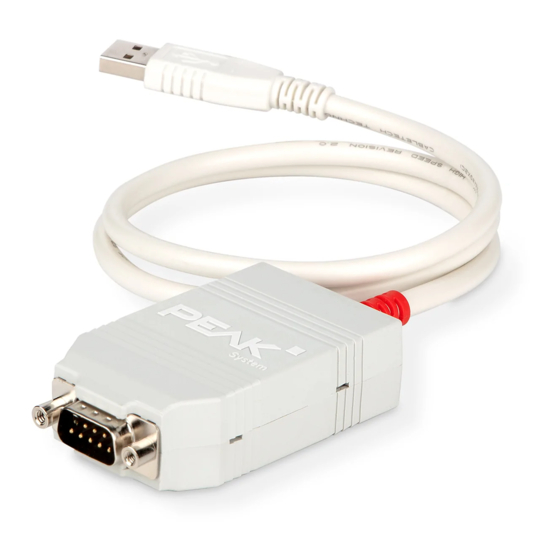
- Page 2 Galvanic isolation for CAN IPEH-002022 interface The cover picture shows both products: the PCAN-USB with the red and the PCAN- USB opto-decoupled with the grey cable strain relief. CANopen® and CiA® are registered community trade marks of CAN in Automation e.V.
-
Page 3: Table Of Contents
PCAN-USB – User Manual Contents Introduction Properties at a Glance System Requirements Scope of Supply Installing the Software and the Adapter Connecting the CAN Bus Connection over D-Sub Connector Voltage Supply of External Devices Activating the Internal Termination Cabling 3.4.1 Termination 3.4.2... - Page 4 PCAN-USB – User Manual 5.2.3 Notes about the License Technical Specifications Appendix A CE Certificate Appendix B Dimension Drawings Appendix C Quick Reference...
-
Page 5: Introduction
PCAN-USB – User Manual Introduction The PCAN-USB adapter enables simple connection to CAN networks. Its compact plastic casing makes it suitable for mobile applications. The opto-decoupled version guarantees galvanic isolation of up to 500 Volts between the PC and the CAN side. -
Page 6: System Requirements
Extended operating temperature range from -40 to 85 °C (-40 to 185 °F) Note: This manual describes the use of PCAN-USB adapter with Windows. You can find device drivers for Linux and the corres- ponding application information on the provided DVD in the directory branch Develop and on our website under www.peak-system.com/linux. -
Page 7: Scope Of Supply
PCAN-USB – User Manual Scope of Supply PCAN-USB in plastic casing Device drivers for Windows 10, 8.1, 7 and Linux (32/64-bit) Device driver for Windows CE 6.x (x86 and ARMv4 processor support) CAN monitor PCAN-View for Windows Programming interface PCAN-Basic for developing applications... -
Page 8: Installing The Software And The Adapter
PCAN-USB – User Manual Installing the Software and the Adapter This chapter covers the software setup for the PCAN-USB adapter under Windows and the connection of the adapter to the computer. Install the driver before you connect the adapter to the computer. -
Page 9: Connecting The Can Bus
9 is not in use at the delivery state. For more information see the next section 3.2. Tip: You can connect a CAN bus with a different transmission standard via a bus converter. PEAK-System offers different bus converter modules (e.g. PCAN-TJA1054 for a Low-speed CAN bus according to ISO 11898-3). -
Page 10: Voltage Supply Of External Devices
External devices with low power consumption (e.g. bus converters) can be directly supplied via the CAN connector. With a solder bridge for the one CAN channel on the PCAN-USB board (casing opened), a 5-Volt supply can optionally be routed to pin 1 and/or pin 9 of the D-Sub connector (for PCAN-USB opto-decoupled to S/N 199999 only pin 1 available). - Page 11 LED must be in the corresponding hole. Push the bottom part of the casing onto the top part until the latches click in. Figure 2: PCAN-USB board (IPEH-002021) to S/N 199999, solder field JP3 for 5-Volt supply Figure 3: PCAN-USB board (IPEH-002021) from S/N 200000,...
- Page 12 PCAN-USB – User Manual Figure 4: Bottom side of the PCAN-USB opto-decoupled board (IPEH-002022) to S/N 199999, solder field R11 for 5-Volt supply Figure 5: PCAN-USB opto-decoupled board (IPEH-002022) from S/N 200000, solder field JP3 for 5-Volt supply 5-Volt supply on the D-Sub connector...
-
Page 13: Activating The Internal Termination
PCAN-USB – User Manual Activating the Internal Termination Only applicable to adapters from S/N 200000. The internal termination can be activated by solder jumpers on the circuit board to terminate one end of the CAN bus. At delivery the termination is not activated. A High-speed CAN bus (ISO 11898-2) must be terminated on both ends with 120 Ohms. - Page 14 PCAN-USB – User Manual Figure 6: PCAN-USB board (IPEH-002021) to S/N 199999, solder fields for the CAN bus termination Figure 7: PCAN-USB opto-decoupled board (IPEH-002022) from S/N 200000, solder fields for the CAN bus termination Termination High-speed CAN bus 120 ...
-
Page 15: Cabling
CAN nodes (CAN interfaces, control devices). The PCAN-USB adapter to S/N 199999 does not have an internal termination. From S/N 200000 it has an optional internal termination with 120 Ohms. See the previous section 3.3 for information about activation. -
Page 16: Maximum Bus Length
PCAN-USB – User Manual 3.4.3 Maximum Bus Length High-Speed-CAN networks may have bit rates of up to 1 Mbit/s. The maximum bus length depends primarily on the bit rate. The following table shows the maximum possible CAN bus length at different bit rates:... -
Page 17: Operation
PCAN-USB – User Manual Operation Status LED The PCAN-USB adapter has a red status LED which can be in one of the following conditions: Status Meaning There's a connection to a driver of the operating system. Slow blinking A software application is connected to the adapter. -
Page 18: Software And Api
PCAN-USB – User Manual Software and API This chapter covers the provided software PCAN-View and the programming interface PCAN-Basic. Monitor Software PCAN-View PCAN-View is simple Windows software for viewing, transmitting, and logging CAN and CAN FD messages. Note: This chapter describes the use of PCAN-View with a CAN adapter. - Page 19 PCAN-USB – User Manual Do the following to start and initialize PCAN-View: Open the Windows Start menu and select PCAN-View. The Connect dialog box appears. Figure 10: Selection of the specific hardware and parameters Select an interface from the list.
-
Page 20: Receive/Transmit Tab
PCAN-USB – User Manual 5.1.1 Receive/Transmit Tab Figure 11: Receive/Transmit tab The Receive/Transmit tab is the main element of PCAN-View. It contains two lists, one for received messages and one for the transmit messages. The CAN data format is hexadecimal by default. - Page 21 PCAN-USB – User Manual Enter the ID, the data Length and the CAN message Data. Note: With the program version 4 of PCAN-View, the DLC field was renamed to Length. Latter reflects the actual data length. Enter a value into the Cycle Time field to choose manually or periodically message transmission.
-
Page 22: Trace Tab
PCAN-USB – User Manual 5.1.2 Trace Tab Figure 13: Trace tab On the Trace tab, the data tracer (data logger) of PCAN-View is used for logging the communication on a CAN bus. During this process the messages are cached in the working memory of the PC. -
Page 23: Pcan-Usb Tab
Thus, it can be uniquely identified while operating several PCAN-USB adapters on a computer at the same time. To identify a PCAN-USB adapter, you first go to the dialog box for selecting the hardware of PCAN-View (Figure 10 on page 19). In the... -
Page 24: Status Bar
PCAN-USB – User Manual 5.1.4 Status Bar Figure 15: Display of the status bar The status bar shows information about the current CAN connection, about error counters (Overruns, QXmtFull) and shows error messages. You can find further information about the use of PCAN-View in the help which you can invoke in the program via the Help menu or with the F1 key. -
Page 25: Linking Own Programs With Pcan-Basic
On the provided DVD, you can find files of the PCAN-Basic programming interface in the directory branch Develop. This API provides basic functions for linking own programs to CAN and CAN FD interfaces by PEAK-System and can be used for the following operating systems: Windows 10, 8.1, 7 (32/64-bit) Windows CE 6.x (x86/ARMv4) -
Page 26: Features Of Pcan-Basic
Use of up to 16 channels for each hardware unit (depending on the PEAK CAN interface used) Simple switching between the channels of a PEAK CAN interface Driver-internal buffer for 32,768 messages per CAN channel Precision of time stamps on received messages up to 1 μs (depending on the PEAK CAN interface used) Supports PEAK-System‘s trace formats version 1.1 and 2.0 (for... -
Page 27: Principle Description Of The Api
PCAN-USB – User Manual Extended system for debugging operations Multilingual debugging output Output language depends on operating systems Debugging information can be defined individually Thread-safe API Tip: An overview of the API functions is located in the header files. You can find detailed information about the PCAN-Basic API on the provided DVD in the text and help files (file name extensions .txt and .chm). -
Page 28: Notes About The License
Notes about the License Device drivers, the interface DLL, and further files needed for linking are property of the PEAK-System Technik GmbH and may be used only in connection with a hardware component purchased from PEAK-System or one of its partners. If a CAN hardware component... -
Page 29: Technical Specifications
NXP PCA82C251 Galvanic isolation PCAN-USB: none PCAN-USB opto: up to 500 V Supplying external PCAN-USB: D-Sub pin 1/pin 9; 5 V, max. 100 mA devices PCAN-USB opto: D-Sub pin 1/pin 9 ; 5 V, max. 50 mA Not connected at delivery... - Page 30 DIN EN 55022:2011-12 Ingress protection IP20 (IEC 60529) Measures Size (w/o cable) PCAN-USB: 75 x 43 x 22 mm PCAN-USB opto: 87 x 43 x 22 mm Cable length about 0.75 m Weight (with cable) PCAN-USB: 78 g PCAN-USB opto: 83 g...
-
Page 31: Appendix Ace Certificate
PCAN-USB – User Manual Appendix A CE Certificate... -
Page 32: Appendix B Dimension Drawings
PCAN-USB – User Manual Appendix B Dimension Drawings Figure 17: View PCAN-USB Figure 18: View PCAN-USB opto-decoupled. The figures don't show the actual size of the product. -
Page 33: Appendix C Quick Reference
Appendix C Quick Reference Software/Hardware Installation under Windows Install the driver from DVD, before you connect the PCAN-USB adapter to the computer. After that, you connect the adapter to a USB port of the computer or of a connected USB hub. The computer can remain powered on.
Need help?
Do you have a question about the PCAN-USB and is the answer not in the manual?
Questions and answers