Advertisement
Advertisement
Table of Contents

Summary of Contents for HiRO 160 Q
- Page 1 Installation instructions for stair lift HIRO 160 Q Version 1.01...
-
Page 2: Table Of Contents
Contents Contents ..........................Page 2 Key to symbols ........................Page 3 Assembly and installation procedure HIRO 160 Q ............Page 4 3.1 Tools ..........................Page 4 3.2 Preparations for work....................Page 5 3.3. Installation of guide rails ....................Page 7 3.4 Installation of drive unit .................... -
Page 3: Key To Symbols
Key to symbols Caution! Risk of personal injury! Attention! Risk of material damage! Note HIRO LIFT Hillenkötter + Ronsieck GmbH Tel. + 49 / 521/ 9 65 52- 0 Fax + 49 / 521/ 9 65 52- 40 Meller Straße 6... -
Page 4: Assembly And Installation Procedure Hiro 160 Q
3. Assembly and installation procedure HIRO 160 Q 3.1 Tools The following tools are required for assembling and installing a HIRO 160 Q stair lift: Percussion drill • Percussion drill bits 6 - 14 mm • Power drill • Set of drill bits and taps for metric thread sizes •... -
Page 5: Preparations For Work
3. Assembly and installation procedure HIRO 160 Q 3.2 Preparations for work The lift unit is supplied in the following packages: 1. Drive unit 2. Seat 3. Cover panels 4. Guide rail beams 5. Production parts list, lift unit drawing with list of supports and fixing materials for the stops 6. - Page 6 3. Assembly and installation procedure HIRO 160 Q Before starting installation work, please check whether the dimensions given in the lift unit drawing agree with the actual dimensions on the installation site. Check against the lift unit drawing and the production parts list to ensure that the lift unit delivered is complete.
-
Page 7: Installation Of Guide Rails
3. Assembly and installation procedure HIRO 160 Q 3.3 Installation of guide rails In lift units where the guide rails are fixed to the wall only, be sure to use through bolts or wall anchors. Where guide rails are fixed to the wall, the fixing points are shown as W1 - W... - Page 8 3. Assembly and installation procedure HIRO 160 Q Note! Before installing the guide rails, the lower guide rail cap must first be attached. For lift units with guide rail supports in the stairwell, the supports must be fitted first as shown in the lift unit drawing.
- Page 9 3. Assembly and installation procedure HIRO 160 Q The size of drill bit to be used depends upon the fixing materials contained in the enclosed accessories kit and shown in the list enclosed with the accessories. Attention! Before drilling, ensure that there are no cables or underfloor heating present in the area concerned.
- Page 10 3. Assembly and installation procedure HIRO 160 Q When fixing the supports, ensure that the supports are correctly aligned both horizontally and vertically. If it is possible to brace the supports to the wall or a similar surface, then the supports must also be fixed by an additional means.
- Page 11 3. Assembly and installation procedure HIRO 160 Q Align the guide rails in all directions using the spirit level. The lift unit drawing shows the height dimensions at each join position between the guide rail beams. Compare the clearance dimensions and the height...
-
Page 12: Installation Of Drive Unit
3. Assembly and installation procedure HIRO 160 Q 3.4 Installation of drive unit At the lift stops, a ready-drilled hole is provided in the upper guide rail tube near the guide rail fixing plate for the purpose of laying the charging cable. - Page 13 3. Assembly and installation procedure HIRO 160 Q To suspend the drive unit in the guide rail, the transport frame must be removed as shown in the picture. Switch the main switch to ON and insert the emergency operation key into the appropriate key switch.
- Page 14 3. Assembly and installation procedure HIRO 160 Q By turning the key switch to the DOWN direction of emergency operation, you can insert the drive unit into the guide rail track. Attention! Ensure that the drive unit and the rollers are not tilted.
- Page 15 3. Assembly and installation procedure HIRO 160 Q The remaining guide rail beams are identified by consecutive numbers. The job number and the guide rail beam number are shown on each guide rail beam. Before inserting the guide rail beam, the charging cable must first be laid in the guide rail tube.
- Page 16 3. Assembly and installation procedure HIRO 160 Q The ends of the guide rails must be fitted together without leaving any gap between them. If necessary, maintain the tension between the guide rails using a chain hoist or a screw clamp.
- Page 17 3. Assembly and installation procedure HIRO 160 Q The dimensions for further aligning the guide rail beams are given in the lift unit drawing. At each join position between the guide rail beams, the drawing gives the height dimension from the stair tread to the centre of the lower guide rail tube.
-
Page 18: Installation Of Chair
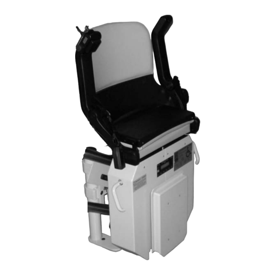
3. Assembly and installation procedure HIRO 160 Q 3.5 Installation of chair Please carry out the following steps to install the swivel seat assembly: Attach the swivel seat assembly to the drive unit with four fixing screws. Connect the armrest controls, swivel seat switch and swivel seat motor to the drive unit using plug- in connections. - Page 19 3. Assembly and installation procedure HIRO 160 Q Connect the plug-in connections for the armrest controls, swivel seat switch and swivel seat motor, as shown in the picture. In the case of lift units with a swivel seat in a...
-
Page 20: Installation Of Upper/Lower Stops
3. Assembly and installation procedure HIRO 160 Q 3.6 Installation of upper/lower lift stops The positive/negative charging pins and the emergency limit switch can be seen in the picture. The accessories kit supplied contains the following parts: 1. Charger unit 2. - Page 21 3. Assembly and installation procedure HIRO 160 Q Install the upper stop in the same way as the lower stop. Fit the long magnet approx. 120 mm before the (round) lift stop magnet. After the learning run has been carried out, the lift always stops at the centre of the round magnet.
- Page 22 3. Assembly and installation procedure HIRO 160 Q A description of the Learning Run and Settings is found in the operating instructions supplied for the P40 control. The circuit diagram and the operating instructions are provided together with the current list of parameters for all setting values.
- Page 23 3. Assembly and installation procedure HIRO 160 Q On the lower set of rollers there are two eccentric guide rollers which are secured at the side with a grub screw. Loosen the grub screws and adjust the guide rollers so that they are just touching the guide rail tube.
-
Page 24: Setting And Testing The Safety Switches
3. Assembly and installation procedure HIRO 160 Q 3.7 Setting and testing of safety switches After fully assembling and installing the lift unit, fill in the installation log and conduct all safety tests and weight checks as described in the log. - Page 25 3. Assembly and installation procedure HIRO 160 Q...
- Page 26 3. Assembly and installation procedure HIRO 160 Q Attention! The main switch must be turned off before carrying out any work on the electronics. Attention! If it is not switched off, the drive motors may be damaged. Note! All defects and damage must be reported to the...
- Page 27 No part of these instructions may be reproduced without our prior approval. Subject to alterations in the interest of technical progress. Hillenkötter + Ronsieck GmbH HIRO LIFT Tel. + 49 / 521/ 9 65 52- 0 Fax + 49 / 521/ 9 65 52- 40 Tel.
Need help?
Do you have a question about the 160 Q and is the answer not in the manual?
Questions and answers