
Related Manuals for BK Precision 1900B


Summary of Contents for BK Precision 1900B
- Page 1 Test Equipment Depot - 800.517.8431 - 99 Washington Street Melrose, MA 02176 TestEquipmentDepot.com Model 1900B, 1901B, 1902B Switching DC Power Supply INSTRUCTION MANUAL...
-
Page 2: Safety Summary
Safety Summary The following safety precautions apply to both operating and maintenance personnel and must be observed during all phases of operation, service, and repair of this instrument. Before applying power, follow the installation instructions and become familiar with the operating instructions for this instrument. - Page 3 WARNINGS AND CAUTIONS WARNING and CAUTION statements, such as the following examples, denote a hazard and appear throughout this manual. Follow all instructions contained in these statements. A WARNING statement calls attention to an operating procedure, practice, or condition, which, if not followed correctly, could result in injury or death to personnel.
- Page 4 Compliance Statements Disposal of Old Electrical & Electronic Equipment (Applicable in the European Union and other European countries with separate collection systems) This product is subject to Directive 2002/96/EC of the European Parliament and the Council of the European Union on waste electrical and electronic equipment (WEEE), and in jurisdictions adopting that Directive, is marked as being put on the market after August 13, 2005, and should not be disposed of as...
-
Page 5: Table Of Contents
Contents Safety Summary ..................1 Introduction ....................6 Controls and Indicators ................7 Front Panel ..................7 Rear Panel ..................8 Operating Instructions ................9 Using the Power Supply ..............10 4.1.1 Connection ................10 4.1.2 Self Test Sequence ..............10 4.1.3 Control Knobs ................ - Page 6 4.3.2 Disconnection ................19 Remote Control ..................19 Analog Remote Control ..............20 5.1.1 Remote Control Connector Setup ........... 20 5.1.2 Using Two External Variable DC Voltage Sources ....21 5.1.3 Using Two 5 kΩ Variable Resistors .......... 23 5.1.4 Enable and Disable the Output ..........
-
Page 7: Introduction
A remote sense terminal (model 1900B only) is also available for use to compensate for voltage drop across load leads. These features make the 1900B Series suitable for a wide range of applications including production testing, telecommunications, R&D, service, and... -
Page 8: Controls And Indicators
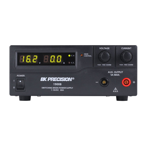
Controls and Indicators Front Panel Figure 1 - Front Panel LED panel meter display with CV/CC indicator Rear Control Indicator (lights up when using Preset/Remote Control/Set mode) Output Voltage Control Knob (control main and auxiliary output voltage) Output Current Control Knob (control main and auxiliary output current limit) Power ON/OFF Switch Auxiliary Output Terminal (max 5 A) Note:... -
Page 9: Rear Panel
Rear Panel Figure 2 - Rear Panel Main Output Terminal (max 60 A for 1900B / 30 A for 1901B / 15 A for 1902B) Note: Please see Section 4.1.5 for more details on using both main and auxiliary output terminals together. -
Page 10: Operating Instructions
This series has three models with different output voltage and current ranges. Make sure you have purchased the correct one. Model Number Output Voltage Range Total Rated Current 1900B 1 – 16 V 0 – 60 A 1901B 1 – 32 V 0 –... -
Page 11: Using The Power Supply
Using the Power Supply 4.1.1 Connection To connect the equipment to the power supply, follow the steps below. 1. Check the rating label of the power supply and confirm that it complies with your AC mains voltage. 2. Connect the power supply to the AC mains using the provided power cord and make sure the Mode Selection Switch is in the Normal position. - Page 12 Front Panel Display Test Segment check Constant Voltage mode indicator check Constant Current mode indicator check Rear control indicator check Return to Constant Voltage mode Start power supply checks Overvoltage protection check Overload protection check...
-
Page 13: Control Knobs
Front Panel Display Test Overtemperature protection check Fan check Output off (remote control mode) Table 2 - Self Test Sequence The LED and other indicators on the front panel will be turned on. When the cooling fan is being checked, a loud fan noise can be heard. After the self checks, the CV, V, and A LED indicators are lit up displaying voltage and 0.0 current. -
Page 14: Manually Zeroing Current Meter Offset
4.1.4 Manually Zeroing Current Meter Offset The power supply will automatically zero the current meter offset when powered up. In case it is needed to reset the current meter to zero during a test, you can manually reset it to zero. This function can be used to zero meter readings < 1 A. 1. -
Page 15: Using Both Main And Auxiliary Outputs
For example, setting the voltage and current outputs for model 1900B (1-16 V, 0-60 A) to 16 V and 60 A would output 16 V at both main and auxiliary terminals and allow you to draw up to a total of 60 A between the two terminals. -
Page 16: Normal Mode
To select a mode, slide the Mode Selection Switch on the rear of the unit. Figure 3 – Mode Selection Switch Note: The power supply is factory preset to Normal Mode with maximum current level. 4.2.1 Normal Mode This is the factory preset mode and the power supply output voltage and current are controlled by the dual action dial knobs. -
Page 17: Analog Remote Control Mode
Section 4.2.4 for details. Recall No. Output Voltage Output Current Maximum 13.8 V Maximum Model 1900B: 15 V Model 1901B: 25 V Maximum Model 1902B: 55 V Table 3 - Default Presets 4.2.3 Analog Remote Control Mode Select this mode to control the output voltage and current via remote control connector. - Page 18 To reset presets to factory settings 1. Press and hold the Voltage Control Knob for 30s to enter Menu mode. 2. When it is showing “CCO”, rotate the Voltage Control Knob until voltage meter shows “rPr”. 3. Then rotate the Current Control Knob until the current meter shows “YES”. 4.
-
Page 19: Remote Sense
The voltage and current settings of corresponding presets P1, P2, or P3 will be shown on the panel meters. Remote Sense (Model 1900B Only) WARNING: Never short the remote sense terminal. Never connect the remote sense terminal in reverse polarity. -
Page 20: Disconnection
Figure 3 shows typical connection between power supply and device for remote sense operation. Figure 3 - Remote Sense Connection The remote sense wire gauge should be at least 22AWG. 4.3.2 Disconnection WARNING: Wrong disconnect sequence will damage the power supply. 1. -
Page 21: Analog Remote Control
Analog Remote Control 5.1.1 Remote Control Connector Setup Set up the provided remote connector plug. Remove the black portion of the remote control connector plug by removing the screw as shown in Figure 4. Figure 4 - Remote Control Connector Solder 5 wires (22AWG) to pins 1, 2, 3, 4, and 5 of pin plug. -
Page 22: Using Two External Variable Dc Voltage Sources
Plug the remote connector plug into the analog remote control terminal of the power supply. Secure the remote connector plug to the terminal socket by locking the connector ring (Figure 6). Figure 6 - Connector Ring Then you can choose one of the following two methods to use the analog remote control feature. - Page 23 Table 4 – Remote Connector Plug Pin Assignment for External Variable Voltage Sources A variable external DC voltage source of 0 – 5 V is fed into the analog remote control terminal to adjust the output voltage level of both Main and Auxiliary output. WARNING: Do not input higher than 5 V, otherwise the overvoltage protection (OVP) will be triggered.
-
Page 24: Using Two 5 Kω Variable Resistors
5.1.3 Using Two 5 kΩ Variable Resistors 1. Make sure the load is disconnected and the power supply is OFF. 2. Prepare two 5 kΩ variable resistors and connect wires from pins 1, 2, 3, and 4 as shown in Figure 7. Figure 7 - Variable 5 kΩ... -
Page 25: Enable And Disable The Output
Output OFF Short to Ground Table 5 – Remote Connector Plug Pin Assignment for Variable Resistors 3. Turn the remote control ON/OFF switch to ON position. 4. Switch on the power supply. 5. Check the output voltage range of the power supply by varying the 5 kΩ variable resistor for voltage adjustment. -
Page 26: Pc Interface Control
PC Interface Control The power supply provides a USB interface for remote control via PC. Please see programming manual for more information on the PC interface control setup, software, and remote commands. The software and programming manual can be downloaded from B&K Precision’s website at www.bkprecision.com. Note: The power supply must be in Normal Mode and operated as a standalone equipment (not connected in series or parallel with multiple supplies) for PC interface control. -
Page 27: Faults And Troubleshooting
Test Equipment Depot - 800.517.8431 - 99 Washington Street Melrose, MA 02176 TestEquipmentDepot.com Faults and Troubleshooting OVP: Overvoltage Protection This unit has a built-in tracking overvoltage protection feature. In the event of the output voltage becoming greater than the set value (see specified range from Specifications section), protection will be triggered and the output power will be cut off. -
Page 28: Olp: Overload Protection
Figure 9 - Overtemperature Protection When you get this warning, switch off the unit and remove all loading. Check your load and output settings and allow the unit to cool down for at least 30 minutes. Check if any of the ventilation is blocked and make sure there is enough clearance around the power supply. -
Page 29: Upper Voltage Limit (Uvl) And Upper Current Limit (Ucl)
Figure 10 - Overload Protection To reset this warning, switch off the unit and remove all connected devices. Switch the unit back on again and double check with caution. If the problem persists, please contact B&K Precision. Upper Voltage Limit (UVL) and Upper Current Limit (UCL) The power supply has upper voltage and upper current limit settings to prevent accidental changes to the output settings. -
Page 30: Fuse Replacement
If current is set beyond the power supply’s upper current limit when increasing the output current setting, the current display will show the following: Figure 12 – Upper Current Limit Fuse Replacement If the fuse blows, the CV or CC indicators will not light and the power supply will not operate. -
Page 31: Specifications
Specifications Models 1900B 1901B 1902B Output Variable Output Voltage 1 – 16 V 1 – 32 V 1 – 60 V Variable Output Current 0 – 60 A 0 – 30 A 0 – 15 A Auxiliary Output Current Voltage Regulation Load (0-100% Load) ≤... - Page 32 Note: All specifications apply to the unit after a temperature stabilization time of 15 minutes over an ambient temperature range of 23 °C ± 5 °C. Specifications are subject to change without notice. *For 220 V version, please request -220V model on order: 1900B-220V, 1901B-220V, or 1902B-220V.
-
Page 33: Certification
Certification CE Declaration of Conformity The power supply meets the requirements of 2006/95/EC Low Voltage Directive and 2004/108/EC Electromagnetic Compatibility Directive. Low Voltage Directive EN 60950-1 EN 61010-1 EMC Directive EN 55011 EN 55022 EN 55024 EN61000-3-2 EN61000-3-3 EN61000-6-1... -
Page 34: Service Information
Test Equipment Depot - 800.517.8431 - 99 Washington Street Melrose, MA 02176 TestEquipmentDepot.com... - Page 36 (Page intentionally left blank)
- Page 37 Test Equipment Depot - 800.517.8431 - 99 Washington Street Melrose, MA 02176 TestEquipmentDepot.com Printed in Hong Kong v022516...
Need help?
Do you have a question about the 1900B and is the answer not in the manual?
Questions and answers