Advertisement
PLEASE NOTE!
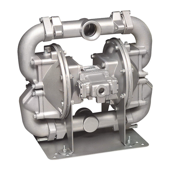
The photos shown in this manual are for general instruction only. YOUR SPECIFIC
MODEL MAY NOT BE SHOWN. Always refer to the parts list and exploded view
drawing for your specific model when installing, disassembling or servicing your pump.
PRINCIPLE OF PUMP OPERATION
This flap swing check valve pump is powered by compressed air and is a 1:1
pressure ratio design. It alternately pressurizes the inner side of one diaphragm
chamber, while simultaneously exhausting the other inner chamber. This causes the
diaphragms, which are connected by a common rod, to move endwise. Air pressure
is applied over the entire surface of the diaphragm, while liquid is discharged from the
opposite side. The diaphragm operates under a balanced condition during the
discharge stroke, which allows the unit to be operated at discharge heads over 200
feet (61 meters) of water head.
Since the diaphragms are connected by a common rod, secured by plates to the
center of the diaphragms, one diaphragm performs the discharge stroke, while the
other is pulled to perform the suction stroke in the opposite chamber.
For maximum diaphragm life, keep the pump as close to the liquid being pumped
as possible. Positive suction head in excess of 10 feet of liquid (3.048 meters) may
require a back pressure regulating device. This will maximize diaphragm life.
Alternate pressuring and exhausting of the diaphragm chamber is performed by
means of an externally mounted, pilot operated, four-way spool type air distribution
valve. When the spool shifts to one end of the valve body, inlet air pressure is applied
to one diaphragm chamber and the other diaphragm chamber exhausts. When the
spool shifts to the opposite end of the valve body, the porting of chambers is reversed.
The air distribution valve spool is moved by an internal pilot valve which alternately
pressurizes one side of the air distribution valve spool, while exhausting the other side.
The pilot valve is shifted at each end of the diaphragm stroke by the diaphragm plate
coming in contact with the end of the pilot spool. This pushes it into position for shifting
of the air distribution valve.
The chambers are manifolded together with a suction and discharge flap-type
check valve for each chamber, maintaining flow in one direction through the pump.
INSTALLATION & START-UP
Locate the pump as close to the product being pumped as possible, keeping
suction line length and number of fittings to a minimum. Do not reduce line size.
For installations of rigid piping, short flexible sections of hose should be installed
between pump and piping. This reduces vibration and strain to the piping system. A
Warren Rupp Tranquilizer
pulsation in flow.
This pump was tested at the factory prior to shipment and is ready for operation.
It is completely self-priming from a dry start for suction lifts of 20 feet (6.096 meters)
or less. For suction lifts exceeding 20 feet of liquid, fill the chambers with liquid prior
to priming.
AIR SUPPLY
Air supply pressures cannot exceed 125 psi (8.61 bar). Connect the pump air inlet
to an air supply of sufficient capacity and pressure required for desired performance.
When the air line is solid piping, use a short length of flexible hose [not less than
3/4" (19mm) in diameter] between pump and piping to eliminate strain to pipes.
WARREN RUPP, INC. A Unit of IDEX Corporation • P.O. Box 1568 • Mansfield, Ohio 44901-1568 USA • (419) 524-8388 • Fax (419) 522-7867
520-010-000 5/03
SERVICE AND OPERATING MANUAL
®
surge suppressor is recommended to further reduce
I M2 c/b T5
CE
II 2GD b T5
Model SA2-A
Model SA2-A
Model SA2-A
Model SA2-A
Model SA2-A
Type 5
IMPORTANT
Read these instructions completely,
before installation and start-up. It is the
responsibility of the purchaser to retain
this manual for reference. Failure to
comply with the recommendations
stated in this manual will damage the
pump, and void factory warranty.
HAZARD WARNING
POSSIBLE EXPLOSION HAZARD can
result if 1, 1, 1,-Trichloroethane,
Methylene
Chloride
Halogenated Hydrocarbon solvents are
used in pressurized fluid systems
having Aluminum or Galvanized wetted
parts. Death, serious bodily injury and/
or property damage could result.
Consult with the factory if you have
questions concerning Halogenated
Hydrocarbon solvents.
DANGER
Before doing any maintenance on the
pump, be certain all pressure is
completely vented from the pump,
suction, discharge, piping, and all other
openings and connections. Be certain
the air supply is locked out or made
non-operational, so that it cannot
be started while work is being done
on the pump. Be certain that approved
eye protection and protective clothing
are worn at all times in the vicinity
of the pump. Failure to follow
these recommendations may result
in
serious
injury
CAUTION
In the event of diaphragm rupture,
pumped material may enter the air end of
the pump, and be discharged into the
atmosphere. If pumping a product which
is hazardous or toxic, the air exhaust
must be piped to an appropriate area for
safe disposition.
CAUTION
Before maintenance or repair, shut off
the compressed air line, bleed the
pressure, and disconnect the air line
from the pump. The discharge line may
be pressurized and must be bled of
its pressure. When used for toxic or
aggressive fluids, the pump should
always be flushed clean prior to
disassembly.
Model SA2-A Page 1
or
other
or
death.
Advertisement
Table of Contents

Related Manuals for Sandpiper SA2-A 5


Summary of Contents for Sandpiper SA2-A 5
- Page 1 SERVICE AND OPERATING MANUAL Model SA2-A Model SA2-A Model SA2-A Model SA2-A Model SA2-A Type 5 I M2 c/b T5 II 2GD b T5 PLEASE NOTE! IMPORTANT Read these instructions completely, The photos shown in this manual are for general instruction only. YOUR SPECIFIC before installation and start-up.
-
Page 2: Air Inlet & Priming
A NOTE ABOUT AIR VALVE LUBRICATION Before pump operation, inspect all The Sandpiper pump’s pilot valve and main air valve assemblies are designed to gasketed fasteners for looseness caused operate WITHOUT lubrication. This is the preferred mode of operation. There may be by gasket creep. -
Page 3: Air Exhaust
CAUTION To re-install the sleeve and spool set, lightly lubricate the o-rings on the sleeve with an o-ring assembly lubricant or lightweight oil (such as 10 wt. air line lubricant). In the event of diaphragm rupture, Re-install one end cap, gasket and bumper on the valve body. Using the arbor press pumped material may enter the air end of the pump, and be discharged into the or bench vise that was used in disassembly, carefully press the sleeve back into the... -
Page 4: Pilot Valve Actuator
REASSEMBLY IMPORTANT Before pump operation, all external All procedures for reassembling the pump are the reverse of the previous gasketed fasteners must be inspected instructions with further instructions as shown: for looseness caused by gasket creep after leaving the factory. Retorque loose 1. -
Page 5: Warranty
Warren Rupp Factory-Authorized Distributor, or Warren Rupp corporate headquarters. ©2003 Warren Rupp, Inc. All rights reserved. ®Warren Rupp, SandPIPER and Tranquilizer are registered tradenames of Warren Rupp, Inc. Printed in U.S.A. 520-010-000 5/03 Model SA2-A Page 5... - Page 6 Grounding The Pump WARNING Take action to prevent static sparking. Fire or explosion can result, especially when handling flammable liquids. The pump, piping, valves, containers or other miscellaneous equipment must be grounded. THE EYELET END IS FASTENED TO THE PUMP HARDWARE. THE CLAMP END IS INSTALLED TO A TRUE EARTH GROUND.
- Page 7 E.I. DuPont. Gylon is a registered tradename of Garlock, Inc. 618-003-110 Plug, Pipe (SS Pump Only) Rupplon and SandPIPER are registered 115-063-080 Mounting Foot, Right Hand tradenames of Warren Rupp, Inc. Ryton is a registered tradename of Phillips...
- Page 8 E.I. DuPont. 900-005-330 Washer, Lock Gylon is a registered tradename of Garlock, Inc. 547-002-110 Nut, Stop Warren Rupp, Rupplon and SandPIPER are registered tradenames of Warren Rupp, Inc. 902-003-000 Stat-O-Seal Ryton is a registered tradename of Phillips 530-036-000 Muffler, Exhaust Chemical Company.
- Page 9 *For units with aluminum wetted end components only. ©2003 Warren Rupp, Inc. All rights reserved. ® Warren Rupp, SandPIPER is a registered tradename of Warren Rupp, Inc. A = Available as Kit # 475-102-000 Printed in U.S.A. B = Available as Kit # 475-101-000...
- Page 10 Delrin, PTFE, Hytrel, and Viton are registered tradenames of E.I. DuPont. Gylon is a registered tradename of Garlock, Inc. Warren Rupp, Rupplon and SandPIPER are registered tradenames of Warren Rupp, Inc. Ryton is a registered tradename of Phillips Chemical Company.
- Page 11 Mansfield, OH 44902 USA Group II, Category 2 GD Models: Air-Operated Double Diaphragm Metallic Pumps Series: G, SA, SB, S, ST, and U under Sandpiper and Marathon Brands SANDPIPER ® A WARREN RUPP PUMP BRAND A WARREN RUPP PUMP BRAND...
Need help?
Do you have a question about the SA2-A 5 and is the answer not in the manual?
Questions and answers