
Related Manuals for Tuxedo TP11KC-DX


Summary of Contents for Tuxedo TP11KC-DX
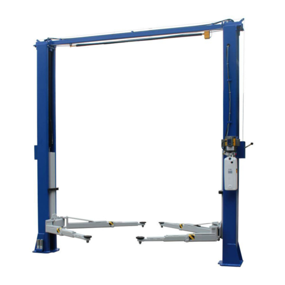
- Page 1 TP11KC-DX Two-Post Clear Floor ‘Bi-Symmetric’ Automotive Lift 11,000 lb. Capacity (2,750 lbs. Max per Arm) Installation & Operation Manual Jun 2017...
-
Page 2: Table Of Contents
4.1.2 Loading Lift 4.1.3 To Raise Lift 4.1.4 While Using Lift 4.1.5 To Lower Lift 4.1.6 Unloading Lift 4.2 Maintenance Instructions 5. Exploded View / Parts List 6. Troubleshooting Guide 7. Power Unit Priming 8. Warranty Policy TP11KC-DX Jun 2017... -
Page 3: Safety Information
6. Failure by the owner to provide the recommended shelter, mounting surface, electrical supply, and ceiling height could result in unsatisfactory lift performance, property damage, or personal injury. 7. The operation of the lift is permitted by authorized personnel only. TP11KC-DX Jun 2017... -
Page 4: Safety Instructions
14. To reduce the risk of personal injury, keep hair, loose clothing, fingers, and all body parts away from moving parts. 15. To reduce the risk of electric shock, do not use the lift when wet, do not expose the lift to rain. TP11KC-DX Jun 2017... - Page 5 20. Anyone who will be in the vicinity of the lift when it is in use should familiarize themselves with the following Caution, Warning, and Safety related decals supplied with this lift, and replace them if they are illegible or missing. TP11KC-DX Jun 2017...
-
Page 6: Technical Manual
Designed and manufactured for a lifting capacity of 11,000 lbs. (Max 2,750 lbs. per Lifting Arm) and is fully capable for lifting vehicles, vans and light trucks by safely holding them in an elevated position. The TP11KC-DX also incorporates the Bi-Symmetric feature, which allows the Arms to be configured for both asymmetrical & symmetrical lifting configurations. - Page 7 Fig. 1 – Front View Spec. POWER UNIT MUST BE INSTALLED ON THE PASSENGER SIDE. FAILURE TO DO SO CAN RESULT WITH INTERFERECE BETWEEN THE POWER UNIT AND SHORT SWING ARM, THUS CAUSING DAMAGE TO POWER UNIT. TP11KC-DX Jun 2017...
- Page 8 Bi-Symmetric (Asymmetric & Symmetric) Configurations NOTE: Power Unit must be mounted on Passenger Side, beside the long/rear Swing Arm. Fig.2a –Top View Spec. Fig.2b - Base Size Spec. TP11KC-DX Jun 2017...
-
Page 9: Installation
Do not use an impact wrench to tighten! Tighten the nut, two or three turns on average after the concrete has cured (28-day cure). If the concrete is very hard only one or two turns may be required. TP11KC-DX Jun 2017... -
Page 10: Tools Required
1-1/8” socket • 13/16” open end wrench • Level (18” minimum length) • Vise grips • Tape measure • Funnel • Hoist or Forklift (optional) • Two 12’ step ladders • 1/4” drive ratchet with 5/16” socket • TP11KC-DX Jun 2017... -
Page 11: Installation Procedure
C. Remove the upper column. Do not stand the columns up now but lay the columns with their flat backs on the floor. 4. Attach the cylinder mounts (uprights) using 4ea 1/2” x 1-3/4” bolts, washers and nuts provided as shown in figure 4a & 4b. Fig. 4a Fig. 4b TP11KC-DX Jun 2017... - Page 12 B. Slide end of padded bar (without a mounting hole) through the slot in the overhead switch assembly. Connect the padded bar to the inside hole in the overhead beam using a spacer and 1/4”-20 Bolt & Lock Nut TP11KC-DX Jun 2017...
- Page 13 8. Install overhead beam to cylinder mounts (uprights) using 2ea 1/2” x 1-3/4” bolts, washers & nuts on each end, (Figs. 7a, 7b, 7c). NOTE: Ensure overhead Limit Switch Assembly is on the Main side column side. Fig. 7a Fig. 7b TP11KC-DX Jun 2017...
- Page 14 A. The carriages should be resting on the same column latches for proper equalization. Ensure to measure the height above the baseplate to each carriage. The measurement should be within 3/8” of each other. Fig. 8a Fig. 8b TP11KC-DX Jun 2017...
- Page 15 15 lbs. effort at midpoint in the column. If the cables are installed correctly, both carriages will raise together. Fig. 8c - Cable Routing TP11KC-DX Jun 2017...
- Page 16 1. Screw in an elbow air-line fitting on the top end of the off side cylinder (Fig. 9b). 2. Screw in another T air-line fitting on the top end of main side cylinder also. (Fig. 9c) 3. Connect the return line from off side cylinder to main side cylinder through fittings. TP11KC-DX Jun 2017...
- Page 17 ( Fig 10) 13. Latch-release cable wiring and accessories mounting. A. Mount the safety latch device on each column as shown in ( Fig. 11a & 11b) Fig. 10 Fig. 11a Fig. 11b TP11KC-DX Jun 2017...
- Page 18 C. Route and adjust the cable tension so that when the handle is pressed down, both latch will be released. D. Put on the covers of the latch device. (Fig 12a & 12b) Fig. 12a Fig. 12b TP11KC-DX Jun 2017...
- Page 19 D. Tighten the gear bolts to 30 – 34 ft. lbs. E. Assemble the arm extensions and lifting pads. Limit arm extensions with bolts & nuts. ( Figs. 14a & 14b) Lifting Pad Fig. 14a - Front Arm TP11KC-DX Jun 2017...
- Page 20 A. Have a certified electrician make the electrical connection to the power unit. Use separate circuit for each power unit, as shown below in the Wiring Diagram. B. Have a certified electrician make the electrical connection for the K2 overhead limit switch to power unit’s switch box, as shown below. TP11KC-DX Jun 2017...
- Page 21 E. Raise the vehicle to full height and lower the carriages onto the safety latches. Lower the vehicle to the floor. F. After cycling the lift ten times with a vehicle on it, recheck the tightness of the anchors to at least 110 ft-lbs. Now the lift is ready for operation. TP11KC-DX Jun 2017...
-
Page 22: Hydraulic Scheme
2. Mesh Filter 3. Gear Pump 4. Motor 5. Relief Valve 6. Check Valve 7. Hydraulic Cylinder(s) 8. Manual Release Valve 9. Pressure Gauge (not supplied) Motor Power 3 HP @ 2,850 RPM Hydraulic Pressure Setting 2,900 PSI TP11KC-DX Jun 2017... -
Page 23: Operation
DO NOT hammer pin down, as this will damage the restraint gear teeth. c. Raise vehicle until the wheels slightly clear the floor, then release the START button. TP11KC-DX Jun 2017... -
Page 24: While Using Lift
After the lift is lowered down onto the ground, remove adapters from under vehicle and swing arms to full drive-thru position before moving vehicle out. IF LIFT IS NOT OPERATING PROPERLY, DO NOT USE UNTIL ADJUSTMENT OR REPAIRS ARE MADE BY QUALIFIED LIFT SERVICE PERSONNEL. TP11KC-DX Jun 2017... -
Page 25: Maintenance Instructions
Check fluid level of lift power unit and refill if required. If Lift stops short of full rise or chatters, contact your service provider. Replace all caution, warning or safety related decals on the lift if unable to read or missing. Reorder labels from service provider. TP11KC-DX Jun 2017... -
Page 26: Exploded View / Parts List
5. Exploded View / Parts List TP11KC-DX Jun 2017... - Page 27 165948T*01-024 flat washer 165948T*01-025 bearing 165948T*01-026 shaft 165948T*01-027 split pin 165948T*01-028 roller 165948T*01-029 shaft 165948T*01-030 cross beam 165948T*01-031 bolt 165948T*01-032 lock nut 165948T*01-033 ceiling limit bat 165948T*01-034 T-type air connector 165948T*01-035 cylinder base 165948T*01-036 large frame TP11KC-DX Jun 2017...
- Page 28 165948T*01-060 motor pump 165948T*01-061 turning board 165948T*01-062 bearing 1# 165948T*01-063 washer 165948T*01-064 fitting adaptor 165948T*01-065 angle air fitting 165948T*01-066 shim 165948T*01-067 adaptor frame 165948T*01-068 switch board 165948T*01-069 cable nut 165948T*01-070 switch cover 165948T*01-071 switch 165948T*01-072 threaded pin TP11KC-DX Jun 2017...
- Page 29 165948T*01-080 bolt 165948T*01-081 large gear 165948T*01-082 curved arm left 165948T*01-083 pad rubber 165948T*01-084 lifting pad 165948T*01-085 short screw slot 165948T*01-086 straight arm extension 165948T*01-087 165948T*01-088 steel cable 165948T*01-089 washer 165948T*01-090 165948T*01-091 curved arm extension 2# TP11KC-DX Jun 2017...
- Page 30 1# 165948T*01-094 arm pin 165948T*01-095 circlips 165948T*01-096 slot 165948T*01-097 air hose (1#) 165948T*01-098 sponge bush 165948T*01-101 bolt 165948T*01-102 long screw slot 165948T*01-103 screw 165948T*01-104 fixing plate 165948T*01-105 Steel ring 165948T*01-106 Ripe grip 165948T*01-107 turnbuckle TP11KC-DX Jun 2017...
-
Page 31: Troubleshooting Guide
Locking latches do not engage. Possible cause: Solution: 1. Latch shafts rusted. 1. Oil latch mechanism. Grease the shaft. 2. Latch spring broken. 2. Replace broken spring. 3. Latch cable needs adjustment. 3. Adjust clamps at cable end. TP11KC-DX Jun 2017... -
Page 32: Power Unit Priming
7. Power Unit Priming TP11KC-DX Jun 2017... - Page 33 8. Warranty TP11KC-DX Jun 2017...
Need help?
Do you have a question about the TP11KC-DX and is the answer not in the manual?
Questions and answers