
Related Manuals for Pavone Sistemi DAT 500

Summary of Contents for Pavone Sistemi DAT 500
- Page 1 Pavone Sistemi pesatura elettronica industriale TECHNICAL MANUAL DAT 500 Weight Indicator/Transmitter with serial and ANALOG output Software version PW13012...
- Page 2 Page II...
-
Page 3: Table Of Contents
TABLE OF CONTENTS PRECAUTIONS ....................Page INTRODUCTION ................... Page TECHNICAL FEATURES ................... Page INSTALLATION ....................Page FRONT PANEL OF THE INSTRUMENT .............. Page USING THE KEYBOARD ................. Page INFO DISPLAY ....................Page 11 VIEWING, ZEROING THE WEIGHT AND SELF-CALIBRATION ......Page 12 SETTING ....................... -
Page 4: Precautions
PRECAUTIONS READ this manual BEFORE operating or servicing the instrument. FOLLOW these instructions carefully. SAVE this manual for future use. CAUTION The installation and maintenance of this instrument must be allowed to qualified personnel only. Be careful when you perform inspections, testing and adjustment with the instrument on. -
Page 5: Introduction
INTROdUCTION The DAT 500 is a transmitter of weight to be combined with the load cells to detect the weight in every situation. The module is easy to install and can be mounted on a front panel. The display allows easy reading of the weight, the status of the instrument, the setting parameters and errors. -
Page 6: Technical Features
TECHNICAL FEATURES Power supply 24 Vdc ± 15 % Max. absorption Insulation Class II Installation category Cat. II Operating temperature -10°C ÷ +40°C (max. humidity 85% non-condensing) Storage temperature -20°C ÷ +50°C Weight display Numerical with 6 red led digits and 7 segments (h 14 4 LEDs of 3 mm Keyboard 4 mechanical keys... -
Page 7: Installation
INSTALLATION GENERAL dATA The DAT 500 is composed of a motherboard, on which you can add the options available; the mother- board is housed in a plastic enclosure for panel mounting. The DAT 500 should not be immersed in water, subjected to jets of water and cleaned or washed with solvents. - Page 8 Connect the cell cable shield to the terminal 2. In the case of the usage of two or more load cells, use special junction boxes (CEM4/C or CSG4/C). Below please find their connection. J-BOX CGS4 DAT 500 +EXC +EXC -SGN...
- Page 9 15 meters (EIA RS-232-C), beyond which you should take the optional RS485 interface. RS485: The serial port RS485 (2-wire) is present in the model DAT 500/ RS485. S.GND To achieve the serial connection, use a suitable shielded cable,...
-
Page 10: Front Panel Of The Instrument
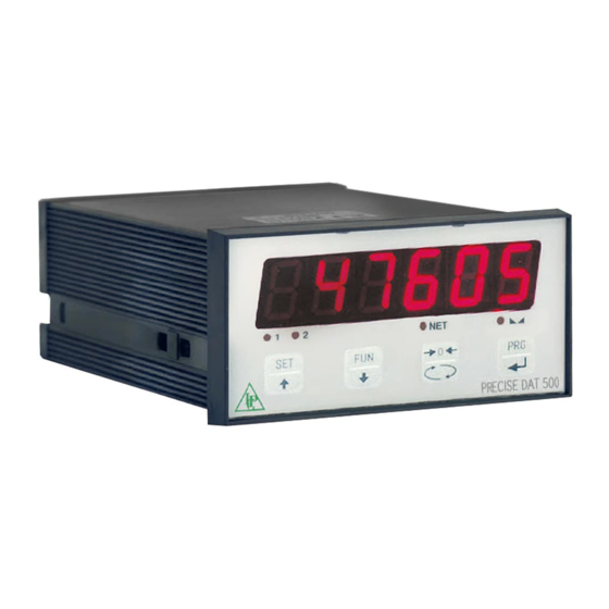
FRONT PANEL OF THE INSTRUMENT The DAT 500 has a bright 6-digit display, 4 status LEDs and four keys. In this operating mode the display shows the weight and the LEDs indicate the status of weight and the setpoints. The set-up parameters are easily accessed and modified through the use of the three front buttons used to select, edit, confirm and save the new settings. -
Page 11: Using The Keyboard
USING THE KEYBOARd The instrument is programmed and controlled through the keyboard which has 4 keys, with the following functions: The selection of one of the key functions is established automatically by the instrument accor- ding to the operation in progress. In general, the management of the programming menus is done by using the keys to scroll through the items;... - Page 12 FUNCTION WHEN SETTING THE NUMERICAL VALUES It increases the value of the flashing digit. It decreases the value of the flashing digit. It goes to the next digit. It confirms the displayed value. FUNCTION WHEN SETTING THE NUMERICAL VALUES It selects the next value. It selects the previous value.
-
Page 13: Info Display
INFO dISPLAY When the instrument is switched ON, you can test the display, then in sequence you can display the identification code of the software and its version. Communication codes in the event of a request for assistance. ERRORS NOTIFICATION In the operation mode, the display can report the following error codes. -
Page 14: Viewing, Zeroing The Weight And Self-Calibration
VIEWING, ZEROING THE WEIGHT ANd SELF-CALIBRATION After being calibrated, at the subsequent switches on, the display shows the current weight. VIEWING THE NET WEIGHT/GROSS WEIGHT Press the key to toggle between the net weight and the gross weight and vice versa. The value displayed is signaled by the LED NET (lit: net weight). - Page 15 The reset command of the gross weight does not run if there is even one of the following conditions: • Unstable weight (with control of the stability of the weight enabled). In this case, the reset command takes effect only if the weight stabilizes within 3 seconds or if the control of the weight stability is disabled (parameter “MOTION “...
- Page 16 PROGRAMMING THE WEIGHT SETPOINTS The set setpoint values are compared with the weight to drive its logic output. The comparison criterion is established in the process of set-up of the logic I / O (see relevant paragraph). To access the Setpoint setting, press the key and follow the instructions on the table below.
- Page 17 KEYBOARd LOCK/UNLOCK FUNCTION A function that allows you to enable or disable the keys individually. When the keys are locked, the only way to access these settings is to press and hold pressed the keys for 3 seconds. For more information on the function, refer to the block diagram below. KEYS CORRESPONDING 3 sec.
-
Page 18: Setting
SETTING GENERAL dATA All functions of the DAT 500 are activated and modified by accessing a simple setup menu, shown on the next page. All settings selected or activated remain stored even after switching off the transmitter. The DAT 500 is preconfigured with a default setting. The following pages show the values of “Default”... - Page 19 FUNCTION WHEN SETTING THE PROSEd VALUES It selects the next value. It selects the previous value. It confirms and store the displayed value. The menu parameters can assume values that can be set or selected. NOTE To exit and save the modified data, press multiple times the key until the indicator returns to the operating mode.
-
Page 20: Chart Of The Menu
dIAGRAM OF THE MENU Page 18... - Page 21 qUICK SET-UP ENTER MENU 5 sec. CapaC Enter Value SEns1t Enter Value Enter Value dEad L Enter Value dspd1J Select Value S1GnaL See Value CaL1br AnaLoG Enter Value StorE? 123456 EXIT MENU 60000 Page 19...
-
Page 22: Setting Parameters
RELATEd TO THE SETTING PARAMETERS Through the setting of the parameters listed below, the theoretical Full Scale DAT 500 calibration is performed. You must complete these steps with the zero calibration described on the next page. The procedure ensures a good accuracy of the system (maximum error <1% FS) if there are no mechanical problems. - Page 23 CAPACITY OF THE WEIGHING SYSTEM Programming the net capacity of the weighing system. Values lower CaL1br AnaLog Conf1G than 1/10 of CaPaC are not accepted. Values: from 1 to 500000 CapaC Enter Value Unit: the same of that displayed Default: 10000 SEns1t Enter Value FIXEd CALIBRATION OF THE WEIGHTING SYSTEM...
- Page 24 RECEIVING dATA FUNCTION UpLoad Receiving function from a serial of a file containing the setup data that will be automatically set in the instrument. SENdING dATA FUNCTION dnLoad Sending function from a serial of a file with the content of the setup memory of the instrument. EXAMPLE OF SETTING/CALIBRATION You must weigh a tank, with empty weight of 750 kg and with a capacity of 1000 liters, containing a product with a specific gravity of 1.33 of which you want to read the weight with a display resolution...
-
Page 25: Calibration
CALIBRATION The calibration described herein should be performed with the use of sample masses and/or product pre-weighed on a weighing scale. Before proceeding with the calibration of the full scale, always perform the zero calibration. During the calibration phase, the display shows the weight intermittently with the inscription CaL. ATTENTION: If you turn off the instrument without exiting the set-up menu, the programming executed is not stored. - Page 26 it cancels the zero calibration. it cancels the calibration of the full scale. LINEARIZATION PROCESS When planning the sample weight, values greater than the full scale, or lower than the previous point, or when the weight is not stable, are not accepted. If the entered value is accepted, it is proposed the next step, otherwise still the same.
-
Page 27: Weighting Parameters
WEIGHTING PARAMETERS The parameters in this menu allow you to adjust the timing of the acquisition and updating of the display and the manual or automatic zeroing that the transmitter performs. WEIGHT FILTER F1LtEr CaL1br ParaN In-oUt This parameter adjusts the refresh speed of the display and the serial and analog output. - Page 28 f1LtEr Select Value Not1on Select Value TRACKING THE ZERO auto 0 0 trac Enter Value This function allows you to perform a momentary zero calibration 0 trac compensating for the temperature drift of the weight. Select Value When you switch off the transmitter, it automatically returns to the 0 band previous zero calibration.
-
Page 29: Input/Output Parameters
INPUT/OUTPUT PARAMETERS SETPOINT 1 OPERATION MOdE NodE 1 ParaN In-oUt SEr1aL Select 4 operation criteria of the setpoint 1 in sequence: The relay output is active in Net Weight mode NodE 1 GROSS The relay output is active in Gross Weight mode Select Value PEAK The relay output is active in Peak mode... - Page 30 Select Value Hyst-1 Enter Value t1NEr1 SETPOINT 2 OPERATION MOdE NodE 2 Enter Value Select 4 operation criteria of the setpoint 2 in sequence: dELay1 The relay output is active in Net Weight mode Enter Value GROSS The relay output is active in Gross Weight mode NodE 2 PEAK The relay output is active in Peak mode...
- Page 31 Hyst-2 Enter Value t1NEr2 Enter Value dELay2 LOGIC INPUTS TEST PROCEdURE tEst1n Enter Value The display shows the inputs status. tEst1n Read and 0 = input disabled change status tstoUt 1= input activated. Read and The input 1 corresponds to the 1a value on the left. change status Enable and disable the inputs to check the corresponding state on the display.
-
Page 32: Serial Output Parameters
SERIAL OUTPUT PARAMETERS This menu allows you to set the serial ports COM1 and COM2 and the communication parameters. The instrument has two independent serial ports connected to a single connector: COM1 with RS232 or RS422 / RS485 interface COM2 with PROFINET interface. BAUd RATE COM1 baUd r In-oUt... - Page 33 Print: Data transfer to the Custom Plus or Custom FT190 printer. In-oUt SEr1aL AnaLoG Value to be selected: baUd r None Select Value Contin prot-1 Demand Select Value Autom- prot-2 Slave Select Value Modbus AddrEs Print Enter Value Default: Modbus Pr-Add Enter Value COM2 PROTOCOL:...
- Page 34 AddrEs Enter Value Pr-Add Enter Value dELay REMOTE COMMUNICATION rEN-Co Enter Value It enables communication with a PC for the setting via the PWIN rEN-Co program Remote connection data F REMOTE COMMUNICATION data F Select Value Parameters of the serial COM1 protocols (parity, bits n., stop bits) except MODBUS.
-
Page 35: Analog Output Parameters
ANALOG - ANALOG OUTPUT PARAMETERS (dAT 500/A ONLY) FULL SCALE F-SCaL ConF1G SEr1aL AnaLoG It’s the weight corresponding to the full scale of the analog output that can be different from the capacity of the weighting system. f-sCaL Value to be set from 000 to 99999. - Page 36 AnzEro Enter Value tEst Select Value ranGE AdJUSTING THE OFFSET (CALIBRATION) offsEt Select Value Measure the analog output value with a multimeter to perform the offsEt calibration of zero (0) and full scale (FS). Use the keys to adjust the analog output. Press and Set Offset -Fs- hold down the key for a rapid change.
-
Page 37: Serial Communication Protocols
SERIAL COMMUNICATION PROTOCOLS The COM1 RS232 serial port is always present, while the COM2 RS485 serial port is present in the absence of the Fieldbus. On the COM2 RS485 weight serial transmission protocols and the MODBUS RTU protocol are handled. CONTINUOUS, AUTOMATIC ANd MANUAL TRANSMISSION PROTOCOL These protocols have been programmed into their programming menu. - Page 38 REQUEST FOR THE NET AND GROSS WEIGHT AND CURRENT PEAK Master: <Addr> “N” EOT DAT 500: “N” <Addr> <status> <net> <gross> <peak> ETX <chksum> EOT CHANGE IN GROSS WEIGHT Master: <Addr> “C” “L” EOT DAT 500: <Addr> “C” “L” ACK EOT CHANGE IN NET WEIGHT Master: <Addr>...
- Page 39 In case of communication error or otherwise unrecognized command from DAT 500, it will respond with the following string: DAT 500: <Addr> NAK EOT FIELDS DECRIPTION The double quotes enclose constant characters (observe upper and lower case); the <and> symbols contain variable numeric fields.
- Page 40 MOdBUS RTU PROTOCOL The addresses listed in the tables below follow the standard address specified in the guidelines of the Modicon PI-MBUS-300. Below please find an excerpt that helps the user to communicate with the instrument. “All data addresses in Modbus messages are referenced to zero. The first occurrence of a data item is addressed as item number zero.
- Page 41 SUPPORTEd FUNCTIONS Function Description 01 (01) READ COIL STATUS (Reading the state of the logic outputs) 02 (02) READ INPUT STATUS (Reading the state of the logic inputs) 03 (03) READ HOLDING REGISTERS (Reading the programmable registers) 04 (04) READ INPUT REGISTERS (Reading the “read only” registers”) 05 (05) FORCE SINGLE COIL (Writing the status of each output) 06 (06)
- Page 42 FUNCTION 2: READ INPUT STATUS QUERY Address Function 1st Input address Nr of Input 2 byte Tot.byte 0x02 0x0000 0x0008 RESPONSE Address Function Nr of bytes Input status 2 byte Tot.byte 0x02 0x01 0x00 5+1*N°byte Input Status: 1 bit for Input. 1st Input address = LSB of Input status. (1 = On, 0 = Off). FUNCTION 3: READ HOLDING REGISTERS QUERY 1st register...
- Page 43 FUNCTION 6: PRESET SINGLE REGISTER QUERY Register ad- Address Function Register value 2 byte Tot.byte dress 0x06 0x0000 0x1234 RESPONSE Register ad- Address Function Register value 2 byte Tot.byte dress 0x06 0x0000 0x1234 The response contains an echo of the query after the command has been executed. FUNCTION 15: FORCE MULTIPLE COILS QUERY 1st Output...
- Page 44 LIST OF THE MOdBUS PROTOCOL HOLdING REGISTERS Address Description Range Value Stored in E2prom 40001 Set point 1 temporary 0 to full scale 40002 Set point 2 temporary 0 to full scale 40003 Command register 1-4,16-19,32 See relative table 40004 Set point 1 permanent 0 to full scale 40005...
- Page 45 COdING dIVISION VALUE TABLE Code Division value 0.001 0.002 0.005 0.01 0.02 0.05 WORd 40303: KEYS MANAGING Writing value 0xFF in the word 40303 will determine the function of the keys in the “remote input”, as per the table below: WORD 40303 1°...
- Page 46 INPUT STATUS BYTES TABLE The Modbus address 40008 is composed by 2 bytes. The conversion of these 2 bytes from hex into binary gives the meaning of each single bit described in this table. Description Bit’s meaning Net weight polarity Gross weight polarity Stable weight Millivolt polarity...
- Page 47 LIST OF INPUT REGISTERS (3X) Address Description 30001 Net weight value (divisions) 30002 Gross weight value (divisions) 30003 A/D converter internal counts (H) 30004 A/D converter internal counts (L) 30005 Millivolt value 30006 Instrument software release 30007 Instrument “On-line” (1= when display shown weight; 0= in all other case) LISTS OF THE COILS (0X) Address Description...
- Page 48 LIST OF THE FUNCTION “STATUS REGISTER” (40082) Function Holding Status Data Stored in Description Codes Register Register E2prom 0000 (00) None of the functions are activated 0003 (03) Analog output zero offset adjustment 40403 0004 (04) Analog output full scale offset adjustment 40404 0005 (05) Test relay output 40083 (analog...
- Page 49 IL PROTOCOLLO PRINT This protocol enables the communication with a printer. The data on the printed report are the following: NET, GROSS and TARE (+ PEAK, if enabled). The print command takes place by pressing the key or by activating the remote input #2. (*) The printed report is issued only if the following conditions are met: • Gross weight positive • Net weight positive...
-
Page 50: Upload And Download Function
UPLOAd ANd dOWNLOAd FUNCTIONS With the download function, the instrument sends the configuration in the e2prom memory via the serial item. This configuration can be saved to a .txt file. With the upload function instead, it is received by the serial item the txt file containing the configuration and the instrument is set with the parameters received. - Page 51 dOWNLOAd (TRANSFER OF CONFIGURATION FROM INSTRUMENT TO PC) 1. From the CONFIG menu, select “DNLOAD” and leave the instru- dnLoad ment in this condition (the instrument is now ready to transfer PRECISE its own configuration to the PC). DAT 400 2.
- Page 52 5. Click on “File”, “Properties” Select “Settings” click on “ASCII Setup” 6. On the upper part of the screen (“ASCII Sending”): Enable “Send line ends with line feeds” Set “Line Delay” at 200 milliseconds On the lower part of the screen (“ASCII Receiving”): Enable “Wrap lines that exceed terminal width”...
- Page 53 9. DAT configuration data received on PC will have this format: 10. Close the connection with a click on button (Disconnect) then close the Hyper Terminal application using the X button on the upper right corner of the screen 11. Click on “Yes” when Hyper Terminal prompts the following: 12.
- Page 54 UPLOAd (TRANSFER OF CONFIGURATION FROM PC TO INSTRUMENT) 1. From the CONFIG menu, select “UPLOAD” and leave the in- upLoad strument in this condition (the instrument is now ready to recei- PRECISE DAT 400 ve from the PC the text file containing the configuration ). 2.
-
Page 55: Troubleshooting
TROUBLESHOOTING PROBLEM POSSIBLE CAUSE SOLUTION The weight gained is not detectable The display shows the because the cell is absent or Check the connections of the cells. O-L message incorrectly connected The weight gained cannot be shown Il The display shows because it exceeds the available five the hyphen in the digits or is greater than the capacity... - Page 56 Page 54...
- Page 57 Via Dei Chiosi, 18 20873 Cavenago di Brianza, MB dECLARES under its own liability, that the instrument called DAT 500, used according to the instructions given in the manual for use and installation, complies with the fol- lowing Directives: EMC Directive 2004-108-EC and subsequent amendments...
- Page 59 PAVONE SISTEMI S.R.L. Via Tiberio Bianchi 11/13/15, 20863 Concorezzo (MB), ITALY T 0039 039 9162656 F 0039 039 9162675 W en.pavonesistemi.it Industrial Electronic Weighing Systems since 1963...
Need help?
Do you have a question about the DAT 500 and is the answer not in the manual?
Questions and answers