Table of Contents
Advertisement
Advertisement
Table of Contents

Related Manuals for Power Probe ECT3000

Summary of Contents for Power Probe ECT3000
- Page 1 p o w e r p r o b e t e k . c o m | 1 . 8 0 0 . 6 5 5 . 3 5 8 5...
-
Page 2: Table Of Contents
Testing the SMART Receiver ......................... 12 Pulse Mode .............................. 12 Locking /Setting the Sensitivity of Short/Grounded Circuit Signal ............14 Locking /Setting the Sensitivity of Open Circuits ................. 14 Direction to Short ............................ 15 How to Use the ECT3000 in Diagnosing Circuits ................16... - Page 3 Contents How to Trace Out a Short Circuit to Chassis Ground ................17 Isolate your Circuit ..........................18 Verify the Short Circuit to Ground ......................18 Short Circuit inside a Wire Harness ......................19 Reception Distance and What that Means ....................20 Tracing Circuits that are Shielded ......................
-
Page 4: Congratulations
Thank you for choosing the Power Probe “ECT3000” (Electronic Circuit Tracer- 3000) The ECT3000 helps quickly locate wiring shorts and opens. The ECT3000 operates just like the trusted Power Probe ECT3000 now with many improvements in functions and features to increase circuit testing accuracy and speed. This instruction booklet will give you some valuable diagnosing tips gathered from the field and from our testing lab. -
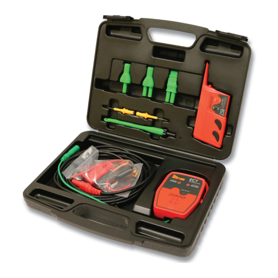
Page 5: Parts
P P T K 0 0 0 3 P P T K 0 0 0 5 P P T K 0 0 0 6 P P T K 0 0 0 7 P P T K 0 0 0 8... -
Page 6: The Smart Transmitter
Signal Lead The signal lead with the green banana jack, plugs into the assortment of adapters, probes, and clips that are provided for you in the ECT3000 kit. These accessories simplify connect- ing to your circuit. Moveable Hanger / Stand Provides multiple convenient mounting options when testing. - Page 7 8 and “Characteristics of the Open Circuit Signal” pg. 9&10) The 2 main features of the ECT3000 is that it transmits a signal into a circuit with the transmitter and then you trace it with the receiver . The easiest way to insure that you are following the problem circuit is to isolate it from other parallel circuits.
-
Page 8: Characteristics Of The Short/Grounded Circuit Signal
Path of Least Resistance Characteristics of the Short/Grounded Circuit Signal: 1. Strongest when flowing exclusively through one wire Major portion of signal goes When the signal is conducting through only one wire, the signal into short (ground) strength is at its maximum because 100% of the signal is travel- ing through that wire exclusively to return back to the negative side of the battery. -
Page 9: Characteristics Of The Open Circuit Signal
A great alternative to the receiver in detecting open circuit signals is to Wet Carpet / Metal/ Shielding Wire Harness Wet Carpet/ Metal/ Shielding Wire Harness use the Power Probe III, IV, or Hook by direct contact. (see “Verify an Open Circuit” pg. 23) -
Page 10: Characteristics Of The Open Circuit Signal
(See: “Locking the Sensitivity for Open Circuits” pg. 14) You can also use the Power Probe III, or Power probe IV for open circuit signal detection by direct contact. (See: “Verify an Open Circuit” pg. 23) -
Page 11: The Smart Receiver
Receiver The receiver is designed to detect the “Grounded Circuit signals” and the open circuit signals from the transmitter. Auto shut-off feature The “Wire Harness Probe” is for probing The receiver will automatically shut-off a harness to detect the open circuit signal. within 10 minutes when it is NOT receiv- (See “Tracing Circuits that are Shielded”... -
Page 12: Battery Installation
Battery Installation 1. To install the batteries, carefully remove two battery covers screws, remove the battery cover on the bottom of the receiver housing and insert (2) AAA batteries into the battery compartment. Be sure the polarity of the batteries are correct then replace the battery cover. - Page 13 When the Receiver is in “pulse mode”: It detects both “grounded” and “open” circuit signals. It picks up and determines strong from weak signals by the pulse frequency rate. The sensitivity is ready to be locked in, by pressing the “Sense Lock / Sense Low” button. It detects and displays the direction to ground or a short circuit.
-
Page 14: Locking /Setting The Sensitivity Of Short/Grounded Circuit Signal
Locking the Sensitivity for Short/Grounded Circuits Fig. A To lock the receiver’s sensitivity for short/grounded circuits, it must be turned on and in “pulse mode”. Hold the “Open & Short Pick-Up” of the receiver parallel and as near to the wire as you can while achieving the most rapid pulse rate. (See: Fig. A) Now press the “Sense Lock/Sense Low button”. -
Page 15: Direction To Short
Short/Ground” to indicate. No reception when No reception when NOT held parallel to the The ECT3000 works equally well with either circuit. NOT held parallel positive chassis ground or negative chassis to circuit. ground. The only thing you need to keep... -
Page 16: How To Use The Ect3000 In Diagnosing Circuits
How to Use the in Diagnosing Circuits Connection Accessories: Included in the ECT3000 are the following connection accessories. • Alligator Clip: for connecting onto any conductor such as a wire or a terminal. • Blade Probe: for tapping into fuse socket terminals and connectors. -
Page 17: How To Trace Out A Short Circuit To Chassis Ground
How to Trace Out a Short Circuit to Chassis Ground A direct short to chassis ground that blows a fuse, is one of the simplest circuits to trace for one simple reason. The majority of the “Grounded Circuit Signal” travels THROUGH THE SHORT CIRCUIT TO CHASSIS GROUND making it easy to trace. This sometimes eliminates the need for isolating the circuit. -
Page 18: Isolate Your Circuit
Verify a Short Circuit to Ground One of the best tools for verifying a short circuit to ground is the Power Probe 1, 2, or 3. To verify a short circuit connect the Power Probe to the circuit and press the power switch forward. -
Page 19: Short Circuit Inside A Wire Harness
Short Circuit Inside a Wire Harness A common occurrence inside of wiring harnesses is that there are two wires running close and parallel to each other. One wire is the positive wire that flows one way and the ground wire that flows back the opposite direction. When the signal source runs closely parallel to the signal return, as in this case, they cancel each other and the signal strength is considerably reduced. -
Page 20: Reception Distance And What That Means
Reception Distance and What that Means. When tracing parallel circuits, you can determine if a one wire has a stronger “Ground- ed Circuit signal” present over another wire. The wire that has a stronger signal carries a larger current. This means the circuit that has the stronger signal also has a lower resistance compared to the other parallel branch. -
Page 21: Tracing Circuits That Are Shielded
Other wires can shield Wet carpet, metal, even Open circuit signals your own hand can shield Open circuit signals. Break / Open Plastic Harness Cover Wire harness probe lets you probe between the wires. Tracing Circuits that are Shielded: Quite often you will need to trace circuits in areas that are shielded from the receiver. -
Page 22: Open Circuit Signal Vs Grounded Circuit Signal
Open Circuit Signal vs Grounded Circuit Signal Open circuit signals can only be present in a circuit when there is a resistance of about 100 ohms or great- er. (Figure A) If a switch was to close in this circuit, (Figure B) the open circuit signals would cease to emit and the short/ Grounded Circuit signal would replace it. -
Page 23: How To Trace An Open Circuit
Probe III or IVto the wire of the transmitting circuit. Contact the probe of the Power Probe III or IV to the open circuit with the open circuit signal applied to it. You should hear the 4 kHz tone from the Power Probe III speaker. -
Page 24: Bench Tracing A Wire Harness
Bench Tracing a Wire Harness Not connected Not connected +Voltage connected connected There are cases where you may have a wire harness removed from the vehicle, sitting on Open Circuit Signal the bench, and tracing an open circuit. Wire harnesses that are removed from the vehicle’s electrical system have only floating wires in Fig. -
Page 25: Tracing Out A Battery Drain Or Current Draw
ECT3000 can assist you in. In cases like this you can inject a signal into the main positive battery cable after removing it from the positive battery post. -
Page 26: Circuit Wiggle And Flex Test
Circuit Wiggle & Flex Test At times it’s necessary to check for intermittent connection problems. The circuit wiggle test allows you to wiggle, twist, pull, push and flex wires or connectors and observe a circuit change. Wiggle, flex & pull the wire to The transmitter monitors the condition of the circuit and alerts you Wiggle, flex &... -
Page 27: Index
page page Index 4 KHz polarized signal ........ 8 power lead ............ 6 accessories ..........16 power/sensitivity lock ........ 11 adapters ............16 pulse mode ..........12 applications of adapters ......16 receiver ............11 reception distance ........20 battery drains ..........25 reception sensitivity ........ - Page 28 Max Operating Relative humidity: 80% (Non-condensation) Max Storage Relative humidity: 80% (Non-condensation) Max Storage Relative humidity: 80% (Non-condensation) Altitude: <2000m Altitude: <2000m Toll Free 800.655.3585 POWER PROBE TEK Local 714.990.9443 760 Challenger St. PDWERPROBETEK.CDII ECT3000 Manual (English V 1.2) 714.990.9478 Brea, CA 92821...
Need help?
Do you have a question about the ECT3000 and is the answer not in the manual?
Questions and answers